manuals.online logo
Brands
  1. Home
  2. •
  3. Brands
  4. •
  5. Forney
  6. •
  7. Welding System
  8. •
  9. Forney 190 MP User manual

Forney 190 MP User manual

Other manuals for 190 MP

1

This manual suits for next models

1

Other Forney Welding System manuals

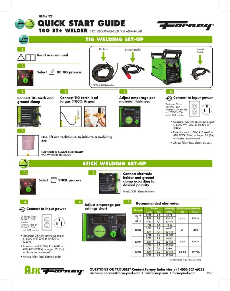
Forney 180 ST+ User manual

Forney

Forney 180 ST+ User manual

Forney 96FI-A User manual

Forney

Forney 96FI-A User manual

Forney 420 User manual

Forney

Forney 420 User manual

Forney 210 User manual

Forney

Forney 210 User manual

Forney TIG User manual

Forney

Forney TIG User manual

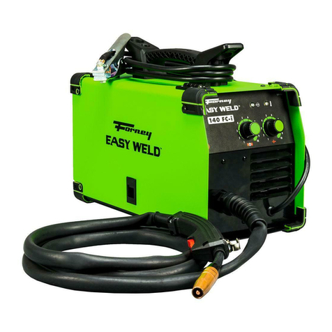
Forney Easy Weld 140FC-i User manual

Forney

Forney Easy Weld 140FC-i User manual

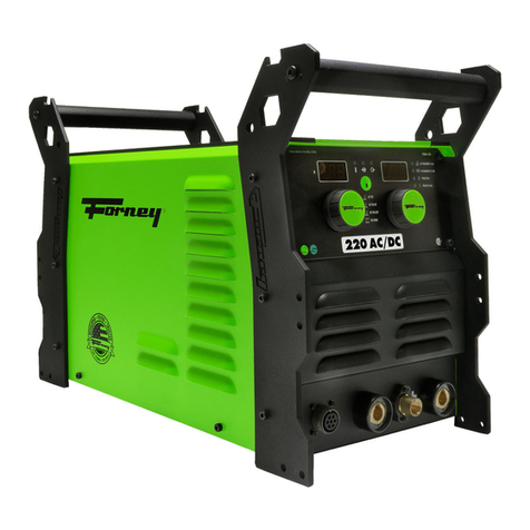
Forney 220 AC/DC User manual

Forney

Forney 220 AC/DC User manual

Forney 190 User manual

Forney

Forney 190 User manual

Forney 270 User manual

Forney

Forney 270 User manual

Forney 180 ST+ User manual

Forney

Forney 180 ST+ User manual

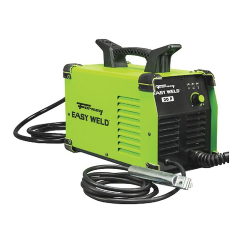
Forney Easy Weld 20P User manual

Forney

Forney Easy Weld 20P User manual

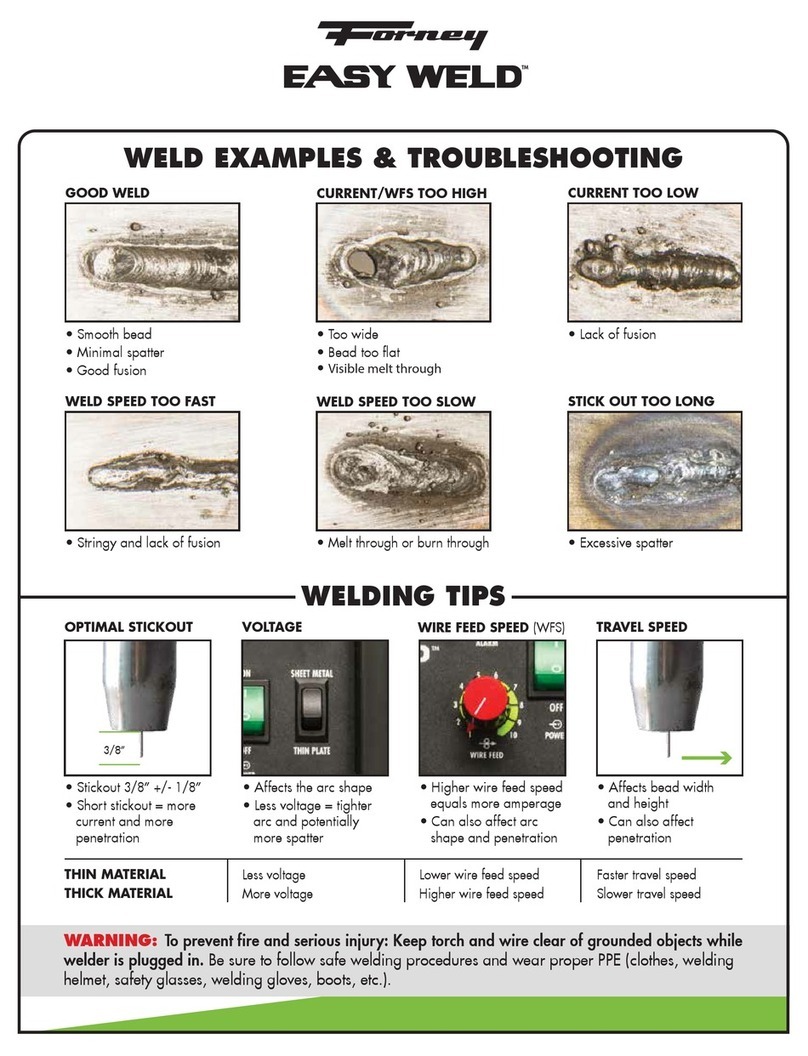
Forney Easy Weld 20P User manual

Forney

Forney Easy Weld 20P User manual

Forney 325P User manual

Forney

Forney 325P User manual

Forney 410 User manual

Forney

Forney 410 User manual

Forney 125 FC User manual

Forney

Forney 125 FC User manual

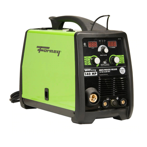
Forney 140 MP User manual

Forney

Forney 140 MP User manual

Forney MIG 180FI User manual

Forney

Forney MIG 180FI User manual

Forney Easy Weld series User manual

Forney

Forney Easy Weld series User manual

Forney Easy Weld User manual

Forney

Forney Easy Weld User manual

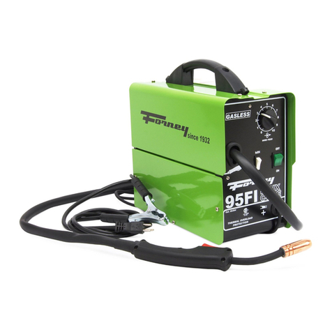
Forney 140 MIG WELDER User manual

Forney

Forney 140 MIG WELDER User manual

Forney 140 MIG WELDER User manual

Forney

Forney 140 MIG WELDER User manual

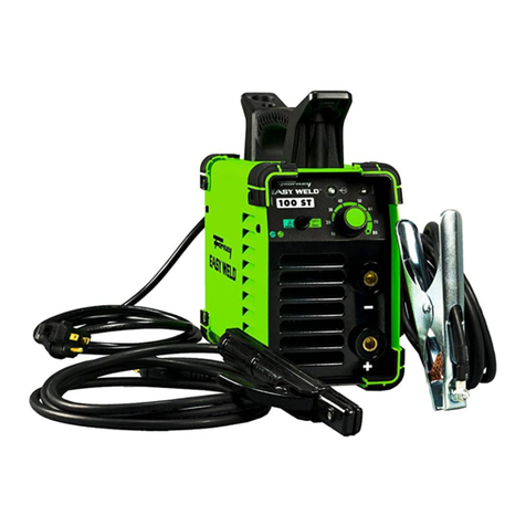
Forney EASY WELD 100 ST User manual

Forney

Forney EASY WELD 100 ST User manual

Forney 210 MIG User manual

Forney

Forney 210 MIG User manual

Forney 45 P PRO User manual

Forney

Forney 45 P PRO User manual

Popular Welding System manuals by other brands

Razorweld RAZORCUT45 instruction manual

Razorweld

Razorweld RAZORCUT45 instruction manual

Lincoln Electric Fleet 500 Operator's manual

Lincoln Electric

Lincoln Electric Fleet 500 Operator's manual

Migatronic OMEGA 220 quick guide

Migatronic

Migatronic OMEGA 220 quick guide

Magmaweld ID 300T DC user manual

Magmaweld

Magmaweld ID 300T DC user manual

Sealey POWERMIG Series instructions

Sealey

Sealey POWERMIG Series instructions

Defort 98291254 user manual

Defort

Defort 98291254 user manual

Hobart Welding Products AirForce 375 owner's manual

Hobart Welding Products

Hobart Welding Products AirForce 375 owner's manual

GF MSA 330 instruction manual

GF

GF MSA 330 instruction manual

Hakko Electronics FX-888D instruction manual

Hakko Electronics

Hakko Electronics FX-888D instruction manual

Abicor Binzel ABIPLAS WELD 100 W operating instructions

Abicor Binzel

Abicor Binzel ABIPLAS WELD 100 W operating instructions

EWM Taurus 355 Basic TDM operating instructions

EWM

EWM Taurus 355 Basic TDM operating instructions

Thermal Dynamics PakMaster 100 XL plus operating manual

Thermal Dynamics

Thermal Dynamics PakMaster 100 XL plus operating manual

Berner PLASMACUT 54 instruction manual

Berner

Berner PLASMACUT 54 instruction manual

Pro Spot PR-155 Assembly instructions

Pro Spot

Pro Spot PR-155 Assembly instructions

Thermal Arc 400S operating manual

Thermal Arc

Thermal Arc 400S operating manual

Lincoln Electric HANDYMIG 170I Operator's manual

Lincoln Electric

Lincoln Electric HANDYMIG 170I Operator's manual

GYS PROTIG 201 AC/DC Original instructions

GYS

GYS PROTIG 201 AC/DC Original instructions

TECNA 4660N Installation and use manual

TECNA

TECNA 4660N Installation and use manual

manuals.online logo
manuals.online logoBrands
  • About & Mission
  • Contact us
  • Privacy Policy
  • Terms and Conditions

Copyright 2025 Manuals.Online. All Rights Reserved.

Adjust wire-feed
speed ( ) and
voltage ( )
Flux-
Cored
* Face the appropriate groove
towards the inside of machine
Set drive roll
Solid
wire
Connect to input power
With contact tip
3/8” from metal,
depress trigger
completely to
initiate arc
Install wire spool
0.023” (0.6mm) - 0.035” (0.9mm) diameter
Feed wire and set pressure
Knob set ~2-3
marks
Remove
consumables
and depress
trigger until
wire comes out.
Replace
consumables
See chart on welder for settings.
Note: Spool gun WFS
adjustment must be made on
the machine.
FIND MORE INFORMATION AT FORNEYIND.COM
4. 5. 6.
7.
9. 10. 11.
8.
Connect MIG gun and
ground clamp
QUESTIONS OR TROUBLE? Contact Forney Industries at 1-800-521-6038 [email protected]
forneyind.com
MIG QUICK START GUIDE
190 MP WELDER
ITEM# 323
Set polarity for MIG (solid wire)
or Flux-Cored
Solid wire Flux-cored
Read user manual
2.
3.
1.
Select Manual MIG
process
Pressure knob
NOTE: If using gas:
2. Attach hose to
regulator and
regulator to
gas bottle
1. Attach gas hose
to machine
MIG Gun Ground
Clamp
• Generator OK with continuous output >
4,000 W (120V) or 10,500 W (240V)
• Extension cord: #12 AWG or larger. 25’
(8m) or shorter extension cords
recommended
For flux-cored welding,
keep contact tip closer
(ideally under 1/4").
Manual MIG
MIG QUICK START GUIDE
190 MP WELDER
ITEM# 323
8” (200mm)
wire spool
4” (100mm)
wire spool
MIG TROUBLESHOOTING TIPS
Improper wire spool installation
Use wire with a diameter between 0.023” (0.6mm) and 0.035” (0.9mm). Larger diameters draw too much amperage.
Trying to weld single pass on material larger than 3/8” (9.5mm) thick is not possible with this machine. Multi-pass recommended for thicker materials.
Welder should be the only thing plugged into the circuit.
• Usually due to low input power.
• Welder should be only thing plugged into circuit.
• Avoid using extension cords. If one must be used, it must be 3 conductor #12 AWG or larger up to 25 feet.
• Generators must be a minimum 4,000W (120V) or 10,500W (240V) continuous output with no low-idle function (or low-idle off), 5% THD Max.
Frequently tripping circuit breaker or exceeding duty-cycle
Low weld output or poor fusion
• Can cause feed issues and inconsistent weld quality.
• Verify all parts are in the proper place. Refer to manual.
Knob set ~2-3 marks
Too little pressure = roll can slip and feed can be erratic.
Too much pressure = can crush wire, causing wire feeding problems and welder damage.
Incorrect drive roll pressure
Trigger must be pulled to initiate the arc. This
will initiate the arc and begin feeding the wire.
DEPRESS THE TRIGGER COMPLETELY
No arc start on contact
• Can cause feed and weld issues and
arc instability.
• Each component must be sized for
wire diameter used.
Mismatched drive roll, liner, or
contact tip size
To ensure maximum quality, always clean
and prepare welding surfaces.
Workpiece Preparation
Connect ground clamp to clean, bare metal. No rust,
paint or other coatings. Attach the ground clamp
directly to the workpiece if you are experiencing issues.
Workpiece Grounding
1. Select process according to diameter of wire being used (TruSet MIG .024”, .030”, or
.035”).
2. Follow steps 3-9 of Manual MIG setup.
3. Push the right knob to light up the Wire/Gas LED then turn the knob to select the wire and
shielding gas combination being used.
4. Push the right knob again to light up the LED then turn the knob to select the
workpiece thickness.
5. The machine will set optimal voltage and WFS. Continue with step 11 of the Manual MIG
setup.
6. The automatic settings can be trimmed up or down with the left knob if you want to refine
the weld settings.
Expert-Tech Tips:
• Best performance is at a trim setting between -5 and +5.
• Step up to the next material thickness to get more penetration.
TruSet™MIG
MIG QUICK START GUIDE
190 MP WELDER
ITEM# 323
8” (200mm) wire spool 4” (100mm) wire spool
3
4
1
6
Connect to input power
4. 6.
Use lift arc technique to initiate a
welding arc
7.
Adjust amperage per
material thickness
Connect TIG torch lead
to gas (100% Argon)
5.
Connect TIG torch and
ground clamp
3.
ELECTRODE IS ALWAYS ELECTRICALLY
HOT WHILE IN TIG MODE
FIND MORE INFORMATION AT
FORNEYIND.COM
TIG TROUBLESHOOTING TIPS
Low weld output or poor fusion
Welder should be the only thing plugged into the circuit.
Frequently tripping circuit breaker or exceeding
duty-cycle
• Not recommended for this machine.
• Output is DC only which is not recommended for TIG
welding aluminum.
Aluminum welding
TIG QUICK START GUIDE
190 MP WELDER (NOT RECOMMENDED FOR ALUMINUM)
ITEM# 323
Read user manual
Select DC TIG process
2.
1.
DC
ONLY
TIG Torch Ground
Clamp
• Usually due to low input power.
• Welder should be only thing plugged into circuit.
• Avoid using extension cords: If one must be used, it must be 3 conductor #12 AWG
or larger up to 25 feet.
• Generators must be a minimum 10,500W continuous output with no low-idle
function (or low-idle off), 5% THD Max.
240V
QUESTIONS OR TROUBLE? Contact Forney Industries at 1-800-521-6038 [email protected]
forneyind.com
• Generator OK with continuous output >
4,000 W (120V) or 10,500 W (240V)
• Extension cord: #12 AWG or larger. 25’
(8m) or shorter extension cords
recommended
To ensure maximum quality, always clean
and prepare welding surfaces.
Workpiece Preparation
Connect ground clamp to clean, bare metal. No rust,
paint or other coatings. Attach the ground clamp
directly to the workpiece if you are experiencing issues.
Workpiece Grounding
• Usually due to low input power.
• Welder should be only thing plugged into circuit.
• Avoid using extension cords. If one must be used, it must be 3 conductor #12 AWG
or larger up to 25 feet.
• Generators must be a minimum 4,000W continuous output with no low-idle function
(or low-idle off), 5% THD Max.
Low weld output or poor fusion
120V
* TIG Torch sold separately
STICK TROUBLESHOOTING TIPS
*Performance may vary by brand
Connect to input power Recommended electrodes
4. 6.
FIND MORE INFORMATION AT FORNEYIND.COM
Adjust amperage per
chart on the inside of
the welder
5.
Electrode Electrode Amperage
3/32” 1/8” 5/32”
E6010
E6011
E6013
E7014
E7018
E308L
Ni55
30-75 75-125 110-165
40-85
40-90
70-90
65-100
40-70
50-65
75-125
70-110
90-140
110-165
75-115
80-95
110-165
115-140
140-190
150-190
105-160
110-135
Connect electrode
holder and ground
clamp according to
desired polarity
3.
Usually
DCEP -
Electrode
Positive
Use 3/16” diameter electrodes or smaller. Some 3/16” will draw too much amperage.
Trying to weld single pass on material larger than 3/8” thick is not possible with this machine. Multi-pass recommended for thicker materials.
Welder should be the only thing plugged into the circuit.
Frequently tripping circuit breaker or exceeding duty-cycle
STICK QUICK START GUIDE
190 MP WELDER
ITEM# 323
Read user manual
Select Stick process
2.
1.
Electrode Holder Ground
Clamp
• Usually due to low input power.
• Welder should be only thing plugged into circuit.
• Avoid using extension cords. If one must be used, it must be 3 conductor #12 AWG
or larger up to 25 feet.
• Generators must be a minimum 4,000W continuous output with no low-idle function
(or low-idle off), 5% THD Max.
Low weld output or poor fusion
110-120V
• Usually due to low input power.
• Welder should be only thing plugged into circuit.
• Avoid using extension cords: If one must be used, it must be 3 conductor #12 AWG
or larger up to 25 feet.
• Generators must be a minimum 10,500W continuous output with no low-idle function
(or low-idle off), 5% THD Max.
208-240V
QUESTIONS OR TROUBLE? Contact Forney Industries at 1-800-521-6038 [email protected]
forneyind.com
• Generator OK with continuous output >
4,000 W (120V) or 10,500 W (240V)
• Extension cord: #12 AWG or larger. 25’
(8m) or shorter extension cords
recommended
To ensure maximum quality, always clean
and prepare welding surfaces.
Workpiece Preparation
Connect ground clamp to clean, bare metal. No rust,
paint or other coatings. Attach the ground clamp
directly to the workpiece if you are experiencing issues.
Workpiece Grounding
Low weld output or poor fusion