Spudnik 8400 Owner's manual

OWNER’S / OPERATOR’S MANUAL
Part # 290092 UP TO 2004
MODEL 8400/8600
PLANTER

Service Centers
Phone:(208)785-0480-Fax: (208)785-1497
E-Mail: [email protected]
Web Site:www.spudnik.com
BLACKFOOT PASCO GRAFTON
584 West 100 North 5802 North Industrial Way 1410 12th St. West
P.O. Box 1045 Pasco, Wa. 99301 Grafton, Nd. 58237
Blackfoot, ID 83221 Phone (509) 543-7166 Phone (701) 352-9603
Phone (208)785-0480 Fax (509) 543-7169 Fax (701) 352-9610
Fax (208)785-1497
HEYBURN PRESQUE ISLE
300 Centennial Dr. 110 Airport Dr.
Heyburn, ID 83336 Presque Isle, Me. 04769
Phone (208)436-8052 Phone (207) 764-4686
Fax (208) 436-9170 Fax (207) 764-4674

02/11/04 2
TABLE OF CONTENTS
PAGE
Introduction……………………………………………………………………………….. 3
Warranty…………………………………………………………………………………... 4
Reporting Safety Defects ..…………………………………………………………….. 5
Safety……………………………………………………………………………………… 6,7
Planter Speed & Seed Spacing Setup..……………………………………………… 9,10
Lubrication & Maintenance..……………………………………………………………. 11
Machine Parts Breakdown
Table of Contents ………………………………………………………………………..
12
Electrical Schematics …………………………………………………………………… 46

02/11/04 3
INTRODUCTION
Welcome to the SPUDNIK line of potato handling equipment. We appreciate
your decision to make our equipment a part of your operation, and look forward to a
long-term partnership. We strive to put the best quality and workmanship into each of
our machines, and hope as you use your MODEL 8400 or 8600 SCOOP/CUP
PLANTER, that you will find this to be true. This owner’s / operator’s manual has been
prepared to aid you in the safe operation and service of your Planter.
Read this manual carefully to learn how to operate your machine safely and
within the design limits of this machine. Failure to do so could result in personal injury
and/or damage to the machine.
This manual is to be considered an important part of this machine and should
accompany it when moved from location to location.
Warranty is provided, as a part of the SPUDNIK EQUIPMENT COMPANY LLC
service program, for customers who operate and maintain their equipment as outlined in
this manual.
OWNER REGISTRATION
Name _____________________________________________
Address ___________________________________________
City ______________________________________________
State / Province _____________________________________
Country ___________________________________________
Model Number ____________ Serial Number _____________
Purchase Date ______________________________________

P.O. Box 1045 - 584 West 100 North - Blackfoot, Idaho 83221
Phone: 208-785-0480 - Fax: 208-785-1497 - www.spudnik.com - E-mail: [email protected]
WARRANTY FOR NEW AGRICULTURAL MACHINERY
A. GENERAL PROVISIONS –The warranties described below are provided by Spudnik Equipment Company LLC.
to the original purchasers of the Agricultural Machinery from Spudnik or authorized Spudnik dealers. These
warranties apply only to equipment intended for sale in the U.S. Under these warranties, Spudnik Equipment
Company LLC will repair or replace, at its option, any covered part which is found to be defective in material or
workmanship during the applicable warranty term. Warranty service must be performed by Spudnik or an authorized
Spudnik dealer which will use only new or remanufactured parts or components furnished by Spudnik. Warranty
service will be performed without charge to the purchaser for parts and labor. The purchaser will be charged for any
premium charged for overtime labor requested by the purchaser, and for any service and/or maintenance not directly
related to any defect covered under the warranties below
B. WHAT IS WARRANTED – All new Spudnik Equipment Company LLC products are warranted for the
number of months or operating hours specified below.
PRODUCT WARRANTY TERM
Rollers, sprockets, roller chain, belt lacing,
bearings
183 days or 720 hrs whichever comes first
All paint to include: Insufficient coverage,
failure of paint, excessive runs and
imperfections. Excessive runs not to exceed
more than 15% of the paint ed surface on the
machine.
12 months from date of purchase
All other materials and workmanship 12 months from date of purchase
C. WHAT IS NOT WARRANTED –(1) Electrical motors or electrical components unless approved by
vendor. (2) Used products. (3) Rock chip damage and other abuse to painted surfaces. (4) Any product
that has been altered or modified in ways not approved by Spudnik Equipment Company LLC.
(5) Depreciation or damage caused by normal wear, lack of reasonable and proper maintenance, failure
to follow the product’s Operator Manual recommendations. (6) Using machine for other than normal
moving of agricultural products during planting, harvest, and processing seasons. Agricultural products
to include: Potatoes, beets, onions, carrots, grains, etc. (7) Changes to sales orders that have been
approved by customer that are incorrect and have the customers’ signature.
D. SECURING WARRANY SERVICE –To secure warranty service, purchaser must (1) report the product
defect to Spudnik and/or authorized dealer and request repair within the applicable warranty term. (2)
Present evidence of the warranty start date. (3) Make the product available to Spudnik or the dealer
within a reasonable period of time and (4) return all faulty parts to Spudnik.
E. WARRANTY SERVICE – All warranty request must (1) be approved by Spudnik Equipment Company
LLC. (2) All warranty must be completed within one year of purchase unless an agreement is made with
Spudnik Equipment Company LLC, to do otherwise, prior to the end of the year. (3) Spudnik Equipment
Company LLC must approve all exceptions to this policy.
(Effective 5/04/2004)

02/11/04 5
SAFETY
You are responsible for the safe operation and maintenance of your SPUDNIK
PLANTER. All operators and anyone doing work or maintenance on Planter must be
trained in the operation, maintenance procedures and related SAFETY information
contained in this manual. All operators and maintenance personnel must receive this
training at least annually to be in compliance with OSHA regulation 1928.57. This
manual is a guide to good safety practices that should be followed while operating
Planter.
The operator is the most important safety device on the Planter. It is the operator’s
responsibility to read and understand ALL operating and safety instructions in this
manual.
ANY UNAUTHORIZED MODIFICATIONS TO MACHINE IS CONSIDERED A
BREACH OF CONTRACT AND REMOVES ALL LIABILITY FROM THE
MANUFACTURER. Unauthorized modification may impair function of machine and/or
safety and could affect the life and warranty of the Planter.
THINK SAFETY! WORK SAFELY!
THE LIFE YOU SAVE MAY BE YOUR OWN!

02/11/04 6
SAFETY
SAFETY ALERT SYMBOL
THE SAFETY ALERT SYMBOL MEANS:
ATTENTION! BECOME ALERT!
YOUR SAFETY IS INVOLVED!
The SAFETY ALERT SYMBOL identifies important safety information on the safety
decals and in this manual. When you see this symbol be alert to the possibility of
personal injury or death.
SIGNAL WORDS:
DANGER, WARNING, and CAUTION are signal words with messages:
DANGER: An immediate and specific hazard, which WILL result in
severe injury or death if proper precautions are not taken.
WARNING: A specific hazard or unsafe practice, which COULD result in
severe injury or death.
CAUTION: Unsafe practices, which COULD result in personal injury if
proper precautions are not taken.

02/11/04 7
SAFETY
GENERAL SAFETY PRACTICES
• The primary responsibility for safe operation of the Spudnik Planter with the
owner/operator.
• OSHA (Occupational Safety and Health Administration) requires that all operators be
trained at the time of initial assignment, and annually thereafter by the employer, in
the safe operation of the Planter.
• Read and understand the operator manual before operating, maintaining, or
adjusting Planter.
• Untrained individuals and children should not be allowed on or around the Planter at
anytime.
• Keep hands, feet, long hair, and clothing away from moving and/or rotating parts.
• Never wear ill-fitting baggy or frayed clothing when working around or on any drive
system component.
• Do not attempt to service, lubricate, clean or adjust Planter while it is running.
• Inspect all mechanisms before starting Planter and replace all worn or damaged
parts.
• Make sure all guards and shields are properly installed and secured before
operating Planter.
• Replace all worn or missing bolts with SAE Grade 5 or better unless specifically
stated otherwise.
• When working on machine parts supported by hydraulic cylinders, ALWAYS support
structure by some other means than cylinders.
• Before applying pressure to the hydraulic system make sure all components, fittings,
steel lines, and hoses are tight and undamaged.
• Do not attempt to ride or mount while the Planter is moving.

02/11/04 8
Planter Setup
Row Spacing – 32”, 34”, 36”, 38”
Requires changing the length of the hopper top tube and the drive shaft
couplings.
Unbolt the hopper, move the hopper feed chain trays, row units, and
wheels to the correct spacing, and then reassemble with the new parts.
Seed Spacing – (Mechanical Drive) The seed spacing sprocket on the jack shaft
behind the drive wheel is generally a tooth count of 2 times the desired spacing
in inches (example: a 10” spacing requires a 20 tooth sprocket). However, the
amount of wheel slip which depends on soil type, will usually require the use of a
sprocket at least one or two teeth smaller than the nominal.
Part # Description
881287 SPRCKT,60A12x1-1/4" BORE 2003 MDL
881288 SPRCKT,60A13x1-1/4" BORE 2003 MDL
881289 SPRCKT,60A14x1-1/4" BORE 2003 MDL
881290 SPRCKT,60A15x1-1/4" BORE 2003 MDL
881291 SPRCKT,60A16x1-1/4" BORE 2003 MDL
881292 SPRCKT,60A17x1-1/4" BORE 2003 MDL
881293 SPRCKT,60A18x1-1/4" BORE 2003 MDL
881294 SPRCKT,60A19x1-1/4" BORE 2003 MDL
881295 SPRCKT,60A20x1-1/4" BORE 2003 MDL
881296 SPRCKT,60A21x1-1/4" BORE 2003 MDL
881297 SPRCKT,60A22x1-1/4" BORE 2003 MDL
881298 SPRCKT,60A23x1-1/4" BORE 2003 MDL
881299 SPRCKT,60A24x1-1/4" BORE 2003 MDL
881300 SPRCKT,60A25x1-1/4" BORE 2003 MDL
881301 SPRCKT,60A26x1-1/4" BORE 2003 MDL
881302 SPRCKT,60A27x1-1/4" BORE 2003 MDL
881303 SPRCKT,60A28x1-1/4" BORE 2003 MDL
Planting Depth - is adjusted with the gage wheel on each row unit.
Seed Switch Gate – the switches which turn the feed chains on and off must be
adjusted so that they are clear of the target when the gate is down, and fully
actuated when up. Also the weights on the gate can be increased or moved out
to keep the gate moving up positively when it empties.
Covering Discs – are adjustable for angle, depth, and width.
Tighten idlers – on row unit drive chain, mechanical drive wheel, hopper chain,
and chemical box drives.

02/11/04 9
Singulation sprocket – controls the ability of the cup chain to eliminate extra
seed pieces.
The size of the sprocket, and the speed of the chain are interrelated. The
singulation sprocket can be made smaller for slower chain speeds (lower ground
speeds, and wider seed spacing), and larger for faster chain speeds (higher
ground speeds and smaller seed spacing).
Singulator sprocket choice:
Choose the preferred planting speed and seed spacing. From the chart below,
choose the singulator sprocket size that corresponds with speed and seed
spacing. If the seed is large, a slightly slower speed, or a larger singulator
sprocket will be indicated on the chart. The opposite is true if the seed is smaller.
Operating
speed in
seeds / minute
Singulator
sprocket
size
M.P.H. @
12” seed
spacing
M.P.H. @
10” seed
spacing
M.P.H. @
8” seed
spacing
500 15 5.6 4.7 3.8
400 13-15 4.6 3.8 3.0
300 11-13 3.4 2.8 2.2
200 7-9 2.3 1.9 1.5
The singulator sprocket is located at the top rear of the row unit. There are five
sprocket choices. The 7-tooth sprocket mounts in the holes nearest to the outer
edge and the 15-tooth sprocket mounts in the holes farthest from the edge of the
center section of the row unit. The other sprockets mount in their respective
holes.
Part # Description
881211 SPRCKT,550A7x 1/2" BORE W/BRNG&BUSHING
881208 SPRCKT,550A9x 1/2" BORE W/BRNG&BUSHING
881212 SPRCKT,550A11x 1/2" BORE W/BRNG&BUSHING
881209 SPRCKT,550A13x 1/2" BORE W/BRNG&BUSHING
881213 SPRCKT,550A15x 1/2" BORE W/BRNG&BUSHING
Final adjustment:
The planter should now be run in the field to do the final adjustments. The field
should be essentially level where the setup is done.
Disengage the shakers by moving them in until the vibration is slight.
Start at the predetermined speed and observe the chain for skips and doubles.
Note: Adequate seed must be in the bowl to correctly set up the planting
unit. See the next section.
If there are essentially no skips, speed up until some skips are observed. If too
many skips are produced, slow down until very few skips. From this base speed,
slow down in increments of 0.1 mph until skips are within the acceptable range. If
this speed is very far from the desired planting speed a larger or smaller
singulator sprocket should be installed and process repeated.
Change the singulation sprocket only if skips cannot be eliminated (chain too
fast), or doubles cannot be reduced acceptably (chain too slow).
Once the singulator sprocket and planting speed is determined, raise the
secondary (top) vibrator to further reduce doubles. Take care too not unduly
increase the skips.

02/11/04 10
Seed level in bowl - If there is not adequate seed in the bowl, skips will result.
Adjust the weight on the seed door to keep adequate seed in the bowl. Adding
weights increases the bowl level.
The maximum seed level should be one inch below the top edge of the seed
weight door at the rear. The bowl level should be observed while planting
because the bowl may overfill when stopping or lifting the planter.
Speed of feed chains and lift cylinders – is adjusted with the tractor hydraulic
flows.
Specifications
Weight: 6-Row -12,500 lb.
4-Row -9,000 lb.
Hopper Capacity: 4-Row 7,000 to 8,000 lb.
6-Row 11,000 to 12,000 lb.

02/11/04 11
LUBRICATION AND MAINTENANCE
• All wheel bearings and wheel hubs should be greased and packed at least
once a year.
• Check wheel lug nuts daily.
• Check tire pressure daily (for 11.2-24/4 16 PLY tire - 54 P.S.I.)
(for 12.5L-16 12 PLY support wheel - 56 P.S.I.)
(for 18/8.50-8/4 gage wheel – 22 P.S.I.)
• To avoid contamination of product all hydraulic fittings must be checked daily
for leaks and replaced or tightened as necessary.
• All bearings are of sealed type and are lubricated by manufacturer. Bearings
will only need to be greased at start of season. Over greasing sealed
bearings will result in seal being broken and rapid failure of bearing. If seal is
broken, bearing should be greased daily until replaced. One pump of grease
at start of season is sufficient.

02/11/04 12
MACHINE PARTS BREAKDOWN
Table of Contents Page.
SAFETY LABELS & SHIELDS
MECHANICAL DRIVE SHIELD ASSEMBLY (OPTION) 17
SAFETY LABEL PLACEMENT 15, 16
SAFETY LABELS 13, 14
PLANTER ASSEMBLIES
CASTER, CRAZY WHEEL ASSEMBLY 27
GAGE WHEEL ASSEMBLY 20
HILLING COULTER ASSEMBLY 24
HILLING COULTER HUB ASSEMBLY 25
HOPPER ASSEMBLY 23
MAIN DRIVE TIRE ASSEMBLY 28
MAIN FRAME ASSEMBLY 26
ROW UNIT ASSEMBLY 18, 19
ROW UNIT COMPONENT ASSEMBLIES 21
ROW UNIT DRIVE ASSEMBLY 29
SEED CONVEYOR ASSEMBLY 22
PLANTER OPTIONS
END TOW HITCH ASSEMBLY (OPTION) 40
HOPPER EXTENSION AND CATWALK (OPTION) 37
MARKER ARMS, 4-ROW PLANTER (OPTION) 35
MARKER ARMS, 6-ROW PLANTER (OPTION) 36
MICROBAND CHEMICAL BOXES ASSEMBLY (OPTION) 33, 34
PLANTER FURROW SHOES (OPTION) 30
REAR TOOL BAR ASSEMBLY (OPTION) 39
ROW UNIT HYDRAULIC DRIVE ASSEMBLY (OPTION) 32
ROW UNIT MECHANICAL DRIVE ASSEMBLY (OPTION) 31
TARP ASSEMBLY (OPTION) 38
PLANTER HYDRAULIC
FOUR CASTERS, CRAZY WHEELS HYDRAULIC ASSEMBLY
(6-ROW PLANTER ONLY)
42
MARKER ARMS HYDRAULIC (OPTION) 45
SEED CONVEYOR HYDRAULIC DRIVE ASSEMBLY 41
THREE CASTERS, CRAZY WHEELS HYDRAULIC ASSEMBLY
(6-ROW PLANTER ONLY)
43
TWO CASTERS, CRAZY WHEELS HYDRAULIC ASSEMBLY
(4-ROW PLANTER ONLY)
44
ELECTRICAL
CLOSE-LOOP LEADER-FOLLOWER PLANTER CONTROL 47 – 52
ELECTRICAL ASSEMBLY 46

SAFETY LABELS
ITEM 1
ITEM 2
ITEM 3
ITEM 4

SAFETY LABELS
ITEM# PART# DESCRIPTION QTY
02/11/04 13
1 300087 LABEL,WARNING,EXPOSED,DRIVE,CAN CAUSE 4
2 300086 LABEL,CAUTION,MOVING,DRIVES,CAN CAUSE 5
3 300097 LABEL,WARNING,HIGH,PRESSURE,OIL,CAN 2
4 300094 LABEL,WARNING,MOVING,MACHINERY,CAN 2

SAFETY LABELS
ITEM 1
300089
ITEM 3
WARNING
CRUSHING HAZARD
KEEP HANDS AND
FEET AWAY FROM
MACHINERY WHILE
RUNNING.
300154
WARNING
MOVING MACHINE
Can cause severe
injury or death.
Do not mount or
dismount moving
machine.
300088
ITEM 2

SAFETY LABELS
ITEM# PART# DESCRIPTION QTY
02/11/04 14
1 300089 LABEL,CAUTION,LOW,SPEED,TIRE,CAN,CAUSE 2
2 300088 LABEL,WARNING,MOVING,MACHINE,CAN,CAUSE 2
3 300154 LABEL,WARNING,CRUSHING HAZARD 2
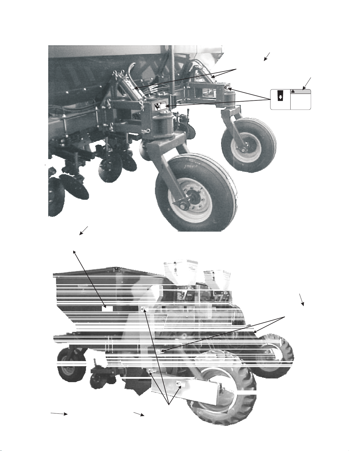
SAFETY LABEL PLACEMENT
BEHIND ALL SHIELDS
WARNING
CRUSHING HAZARD
CRUSHING HAZARD
KEEP HANDSAND
FEETAWAY FROM
MACHINERYW
HILE
RUNNING.
KEEP HANDS AND
FEETAWAY FROM
MACHINERYWHILE
RUNNING.
300154
300154
WARNING
CRUSHINGHAZARD
CRUSHINGHAZARD
KEEPHANDS AND
FEETAWAY FROM
MACHINERYWHILE
RUNNING.
KEEPHANDS AND
FEETAWAY FROM
MACHINERYWHILE
RUNNING.
300154
300154
.
WARNING
CRUSHING HAZARDCRUSHING HAZARD
KEEP HANDS AND
FEET AWAY FROM
MACHINERY WHILE
RUNNING.
KEEP HANDS AND
FEET AWAY FROM
MACHINERY WHILE
RUNNING.
300154300154
3
4
1
.
2
5
6

SAFETY LABEL PLACEMENT
ITEM# PART# DESCRIPTION QTY
02/11/04 15
1 300097 LABEL,WARNING HIGH PRESSURE OIL CAN CAUS 2
2 300154 LABLE,WARNING CRUSHING HAZARD 2
3 300094 LABEL,WARNING MOVING MACHINERY CAN CAU 2
4 300089 LABEL,CAUTION,LOW,SPEED,TIRE,CAN,CAUSE 2
5 300086 LABEL,WARNING MOVING DRIVES CAN CAUSE 3
6 300087 LABEL,WARNING EXPOSED DRIVE CAN CAUSE 3

SAFETY LABEL PLACEMENT
BEHIND ALL SHIELDS
4
3
2
1
4
WARNING
MOVING MACHINE
Can cause severe
injuryor death.
MOVING MACHINE
Can cause severe
injuryor death.
Donot mount or
dismountmoving
machine.
Donot mount or
dismountmoving
machine.
300088300088
WARNING
MOVING MACHINE
Can cause severe
injuryor death.
MOVING MACHINE
Can cause severe
injuryor death.
Donot mount or
dismountmoving
machine.
Donot mount or
dismountmoving
machine.
300088300088
WARNING
MOVING MACHINE
Can cause severe
injury or death.
MOVING MACHINE
Can cause severe
injury or death.
Do not mount or
dismount moving
machine.
Do not mount or
dismount moving
machine.
300088
55
This manual suits for next models
1
Table of contents
Popular Seeder manuals by other brands


GREAT PLAINS
GREAT PLAINS Turbo Max 2400TM Assembly manual

AerWay
AerWay AWATS-100-AG-4 Owner's/operator's manual

Equalizer
Equalizer Econo 4000E Operator's manual

GREAT PLAINS
GREAT PLAINS 3S-3000-3210 Operator's manual

Apex Digital
Apex Digital XA1200 Operation manual

John Shearer
John Shearer Pasture Renovation Drill Operator's manual