Equalizer Econo 4000E User manual
OPERATOR MANUAL
3-SECTION MIN-TILL AIRSEEDER
4500E - 7500E

2
CONTENTS
1. INTRODUCTION..................................................................................................................9
2. HOW TO BEGIN ................................................................................................................. 9
2.1 INTEGRATION WITH THE TRACTOR ...................................................................... 9
2.2 CALIBRATION ...................................................................................................... 10
2.3 IN THE FIELD ...................................................................................................... 10
3. AIR HOPPER .....................................................................................................................12
3.1 GOLDEN RULES. .................................................................................................. 12
3.2 TOOL INTEGRATION. .......................................................................................... 12
3.3 OPERATION AND SETTINGS............................................................................... 14
3.4 CONFIGURATION OF THE DISTRIBUTION SYSTEM.............................................. 19
4. CALIBRATION...................................................................................................................20
4.1 MAINTENANCE AND INSPECTION........................................................................ 21
5. FRAMES ............................................................................................................................22
5.1 GOLDEN RULES................................................................................................... 22
5.2 ADJUSTMENTS .................................................................................................... 22
5.3 MAINTENANCE AND INSPECTION........................................................................ 23
6. TINE UNITS .......................................................................................................................24
6.1 GOLDEN RULES................................................................................................... 24
6.2 ADJUSTMENTS .................................................................................................... 24
7. SPRAY EQUIPMENT.........................................................................................................28
7.1 GOLDEN RULES................................................................................................. ..28
7.2 ADJUSTMENTS ............................................................................................... ….28
7.3 MAINTENANCE AND INSPECTION. ....................................................................... 28
8. SPECIFICATIONS .............................................................................................................29
8.1 TYRE PRESSURE. ................................................................................................ 29
8.2 OIL AND LUBRICANTS. ......................................................................................... 29
9. PROBLEM SOLVING ........................................................................................................30

3
HEALTH AND SAFETY
The words DANGER, WARNING or CAUTION are used with the safety alert symbol. Learn to
recognize the safety alerts, and follow the recommended precautions and safe practices.
THREE WORDS ARE USED IN CONJUNCTION WITH THE SAFETY-ALERT SYMBOL:
Replace any DANGER, WARNING, CAUTION or instructional decal that is not readable or is
missing. The location and part number of these decals is identified later in this section of the
manual. The words Important and Note are not related to personal safety but are used to give
additional information and tips for operating or servicing this equipment.
IMPORTANT: Identifies special instructions or procedures which, if not strictly observed could
result in damage to, or destruction of the machine, process or its surroundings.
NOTE: Indicates points of particular interest for more efficient and convenient repair or operation.

4
GENERAL OPERATION
DO NOT RIDE!! Do not allow riders on
the implement when in motion.
• Do not allow extra riders in the tractor
unless an instructor seat and seat belt
are available.
• Check behind when backing up.
• Reduce speed when working in hilly
terrain.
• Never allow anyone within the
immediate area when
operating machinery.
• Stand clear when raising or lowering wings.
• Keep all shields in place, replace them if removed for service work.
TRACTOR OPERATION
Be aware of the correct tractor operating procedures,
when working with implements.
•Review tractor operator’s manual.
•Secure hitch pin with a retainer and lock drawbar in
centre position.
CHEMICALS
•Use extreme care when cleaning, filling or making adjustments.
•Always read granular chemical or treated seed
manufacturer’s warning labels carefully and
remember them.
•Wear close fitting clothing and appropriate personal
protective equipment for the job as specified by the
chemical and/or seed manufacturer.
•Always wear safety goggles, breathing apparatus and gloves
when handling with granular
chemical or treated seed.

5
•Do not feed any treated seed to livestock. Treated
seed is poisonous and may cause harm to persons
or livestock.
•Wash exposed skin immediately - do not leave
chemicals on your skin.
•Properly store chemicals in original containers with
labels intact per the manufacturer’s instructions.
•Always follow the manufacturer’s operating
instructions and warning labels when operating an
ammonia tank with the equipment.
•Do Not enter Air Cart tank unless
another person is present and the
tractor engine has been shut off.
TRANSPORTING
•Be aware of the height, length and width of implement. Make turns carefully and be aware of
obstacles and overhead electrical lines.
•Always travel at a safe speed. Do Not Exceed 20 m/h (32 km/h).
•Use an agricultural tractor that is large enough with sufficient braking capacity so that the weight
of the loaded equipment towed does not exceed 1.5 times the weight of the tractor.
•Use flashing amber warning lights, turn signals and Abnormal emblems when on public roads.
•Do not transport in poor visibility.
•The slow moving vehicle with Abnormal emblem and reflectors must be secured and be visible
on the machine for transport.
•Avoid soft surfaces, the additional wing weight on the center wheels could cause the machine to
sink.
•Ensure safety chain is attached correctly to the towing vehicle and the hitch of the implement.
•Check that wings are firmly seated on transport wing stops, and wing lift valve and opener valve
are in locked position.
•Be familiar with and adhere to local laws.
6
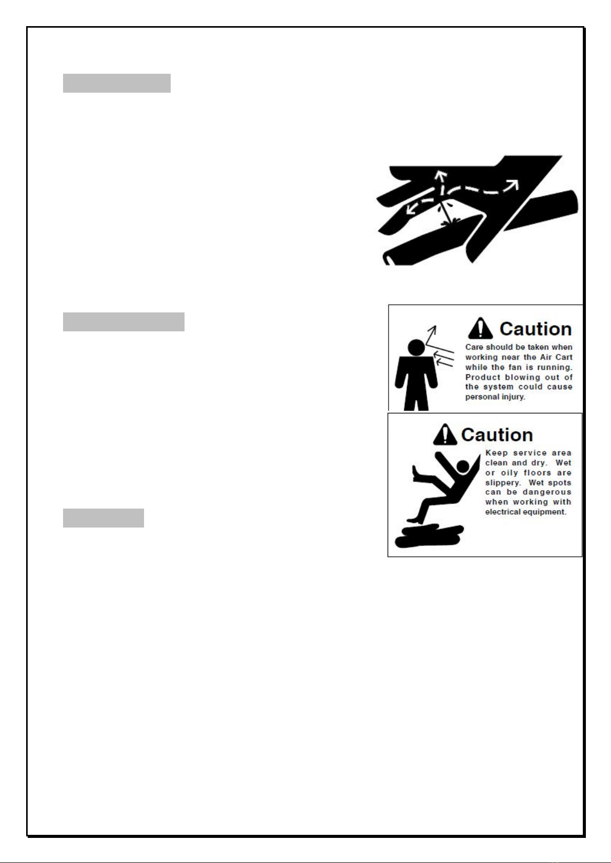
HYDRAULICS
•Do not search for high pressure hydraulic leaks without hand and face protection. A tiny, almost
invisible leak can penetrate skin, thereby requiring immediate medical attention.
•Use cardboard or wood to detect leaks - never your
hands.
•Double check that all is clear before operating
hydraulics.
•Never remove hydraulic hoses or ends with machine
elevated. Relieve hydraulic pressure before
disconnecting hydraulic hoses or ends.
•Maintain proper hydraulic fluid levels.
•Keep all connectors clean for positive connections.
•Ensure all fittings and hoses are in good condition.
•Do not stand under wings.
MAINTENANCE
•Shut tractor engine off before making any
adjustments or lubricating the machine.
•Block machine securely to prevent any movement
during servicing.
•Wear close fitting clothing and appropriate personal
protective equipment for the job.
•Always wear safety goggles, breathing apparatus
and gloves when working on seeder filled with granular
chemical or treated seed per the manufacture’s
instructions.
•Do not modify the machine.
STORAGE
•Store implement away from areas of main activity.
•Level implement and block up securely to relieve pressure
on jack.
•Do not allow children to play on or around stored implement.

7
SAFETY SIGNS

8

9
1.INTRODUCTION
This document deals with technical and other information about Equalizer Econo Min-Till Tine
Seeder, which enables the user to correctly choose and apply the necessary settings for the
equipment to work effectively.
NB: Study this document carefully before attempting to use the product.
Damage is inevitable if the implement is used incorrectly.
2. HOW TO BEGIN
2.1 INTEGRATION WITH THE TRACTOR
Connect the tractor to the planter and connect the hydraulic hoses.
NOTE:Make sure the return hose of the fan motor / oil cooler is connected to the correct hydraulic
port in accordance to the tractor’s manual.
UNFOLDING THE PLANTER
1. Unfold the planter until all wheels are safely on the ground and the planter can float properly.
(Refer to page 10)
TOW-EYE SETTINGS
2. Position the planter on a level surface. Lower the planter until the points of the
shears just touch the ground. Set the draw bars tow-eye so that the front and rear shears
engage the ground simultaneously. (Refer to page: 22)
TINE PRESSURE
3. Set the tine hydraulic pressure to 8 - 9 MPa.
NOTE:The tine pressure line is linked with the lifting and lowering cylinders of the planter. Use
the selector valve to select the Tine setting to charge and activate the accumulator. (Refer to
page: 26)
FAN AND AIR PRESSURE
4. Activate the fan.
NOTE:Set the tractor's flow control valve to the fan to less than 25% of full flow, before it is
switched on. (Refer to page: 12 & 13)
5. Make sure all lids and metering units are tightly sealed, and no air leaks are
present.
6. Regulate the fan speed to create a pressure of 2 kPa on the tank registering
the lowest pressure. Make adjustments to the speed until the desired pressure is achieved,
calculated from the accompanying chart. (Refer to page 17)
TOTAL APPLICATION
QUANTITY KG / HA ALL
FERTILIZERS COMBINED
AIR PRESSURE IN THE TANK
REGISTERING THE LOWEST
READING
5-50 kg/ha
1.5 kPa
50-125 kg/ha
1.5 – 2.0 kPa
125-200 kg/ha
2.0 – 2.8 kPa
200-275 kg/ha
2.8 – 3.5 kPa
275-350 kg/ha
3.5 – 4.0 kPa

10
CONTACT DRIVE WHEEL
7. Set the contact drive so that it just touches the main wheel when the point of the shears just
touches the ground.
SEED DEPOSITORS
8. Set the seed depositor depth to the 2nd groove.
NB:The final adjustment is done after the ideal working depth and speed is determined. (Refer
to page 25)
2.2 CALIBRATION
SEED AND FERTILIZERS
1. The calibration pendulum rotates + / -77 times for every 50 linear meters.
2. Use the directive in the manual for calibration weight calculations.
3. Remove the connecting link pin on the drive shaft.
4. Catch the product simultaneously in both tanks under the air hopper.
(Refer to page 20)
SPRAY SYSTEM
5. The spray nozzles deliver + / - 100 liters of water per hectare at 180 KPa at 6 km / h.
6. Set the pressure while the planter is at 6 km / h at 180 KPa.
7. For a more accurate setting, capture the water dispersed by one nozzle over a
given distance or time.
NB:The nozzles are spaced at 500 mm, the same as a normal sprayer.
(Refer to page: 23).
2.3 IN THE FIELD
UNFOLDING/FOLDING THE PLANTER
STANDARD V FRAME:
UNFOLDING:
1. Insert the “wings fold’’ and ‘’wings unfold’’ hydraulic hoses into the tractor.
2. Apply flow the “wings unfold” hydraulic hose to lower the wings from the vertical to the horizontal
position. Keep extending the wing fold cylinders until they reach end of stroke which means the
pin will be sitting in the middle of the slot. NB: this is very important as it allows the wings of the
planter to float.
FOLDING:
1. Insert the “wings fold’’ and ‘’wings unfold’’ hydraulic hoses into the tractor.
2. Apply flow to the “wings fold” hydraulic hoses to raise the wings to the vertical position. Keep on
retracting the cylinders until the wings reach the transport location. NB: ensure the transport
locks are in place before transport.

11
SEED AND FERTILIZER DISTRIBUTION
1. With the planter stationary, make sure the shear points are just above ground
level and the fan is turned on: Turn the contact drive wheel twice. Check that seed and fertilizer
appears at each seed / fertilizer depositor.
WORKING DEPTH
2. The ideal depth is at a level where the very top portion of the tungsten on the shear sits just
below the surface of the soil. NB:At planting speed the soil is thrown above the suggested
height, as discussed above, giving one the illusion that you are planting too deep.
WORKING SPEED
3. The speed is determined by the effect of ground dispersion at the back rows
on to the front rows. Speed can be increased as long as all the rows are uniformly displayed
after the planter has planted. NB:Loose clumps of soil that have rolled from the rear rows to the
front rows are not necessarily a problem. (Refer to page: 26)
SEED PLACEMENT
4. The most common depth setting is on groove 2. It has a planted result of 10 to 15 mm
depending on soil conditions.
5. Work for 100 m, then stop and check the depth at which the seed was planted.
Adjust if necessary. (Refer to page: 25)

12
3. AIR HOPPER
3.1 GOLDEN RULES
1. The lids should always be sealed while the machine is in operation.
2. When filling the bins always use the provided sieve.
3. Take care with fertilizer left over in the bins. Turn the measuring unit before operations begin.
This will prevent the fertilizer from damaging the Zero Max gearbox at the metering unit.
4. Take care with transportation over long distances as the fertilizers tend to become
compact in the metering unit which may damage the Zero Max gearbox.
Equalizer air hoppers work on the so-called closed tank system. It simply means that when the tank
lids are tightly sealed the principle will apply that all air entering the system has only one way out,
which is in the direction where the seed or fertilizer should be fed.
NB: The main requirement of the system is that the metering unit is 100% sealed to ensure
accurate distribution of both the seed and the fertilizer.
3.2 TOOL INTEGRATION
3.2.1 TRACTOR HYDRAULIC DRIVE
Only tractors with "closed center" hydraulic systems are suitable for this setup: Flow
Control on the remote ports of the tractor is essential.
In cases where the fan motor is driven by the tractor's hydraulic system the fan speed must be
regulated using the specific regulating valve on the tractor.
Follow the procedure for the set up of the fan speed through the tractor's flow control:
Safety Valve
(20 Bar)
½ Inch Pressure Line
(from the tractors quick
coupler)
1 Inch Return Line
(directly to the tractors
oil reservoir)

13
Safety Valve
1. The 1 inch return line must be connected to the relevant return line port (dumping port) for
constant oil flow systems, according to the tractor's manual. It may not be connected to the
normal quick couplers of the tractor. The system is equipped with a safety valve of 20 Bar. If
the return line is not coupled and oil pressure exists, the pressure line allows the safety valve to
release the oil in order to protect the oil cooler.
NB: With high oil flow rates the oil cooler can still burst.
2. The ½ inch pressure line is connected to the standard
quick couplers.
3. Set the oil flow rate at the chosen connector to a ¼ of its
capacity before it can be activated for the first time.
4. With the hydraulic pressure line and the return line
coupled to the tractor, make sure the lids of the bins
and metering units are sealed.
5. Activate the tractor control valve to channel oil flow to the fan motor.
6. Make adjustments to the oil flow rate to change the air pressure reading to correspond with the
table in clause 3.3.3.
3.2.2 EXTERNAL HYDRAULIC PTO PUMP DRIVE
Oil Tank
Pump
PTO-Gearbox
Oil Level Indicator
Filter
Flow
Regulating
Valve

14
Set the fan speed by using the FLOW CONTROL VALVE infront of the pressure gauge on
the fan motor.
NOTE:
•Pump selection is done depending on the tractors PTO drive speed: 540 rpm or 1000 rpm.
•NB:The 540 pump may under no circumstances be driven at the 1000 rpm setting.
•The gearbox must be well aligned with the tractor PTO – to prevent wear of the gearbox unit.
•Maintenance of the system must be done according to the Maintenance and Inspection clause
4.1.
3.3 OPERATION AND SETTINGS
3.3.1 OPERATION OF THE METERING UNITS
The metering unit uses a pintle cog to roll the product from the tank. The product falls into the air
stream which distributes it through the network of pipes. The pintle cog is kept clean using a nylon
brush. The amount of product that can be measured is determined by the speed of the roller. The
ratio between the roller speed and the drive wheel speed is regulated by the Zeromax gearbox.
The drive wheel generates a constant ground speed which can be manipulated by the gearbox to
generate a specific roller speed for a chosen calibration weight.
Water
Emptying Cover
Fan
Tank
Lid
Inspection Cover
Calibration Cover
Pintle Cog & Brushes
Fan Manifold

15
THE METERING UNIT HAS 3 COVERS, EACH FOR A SPECIFIC
PURPOSE
1. CALIBRATION COVER
•Is removed to catch the product for calibration purposes.
•Can be opened at any time, even if the bin is full.
2. INSPECTION COVER
•Is removed to inspect and clean the roller and brush.
•Can be opened at any time even if the bin is full.
3. EMPTYING COVER
•Is removed only to empty the bin.
NOTE: This door may NOT be opened for any reason whatsoever when the bin is full. It is
impossible to reseal the tank once opened when product is inside.
NOTE: The rotation direction of the measuring roller seen from the gearbox: Clockwise
Inspection
Cover
Emptying
Cover
Calibration
Cover

16
3.3.2 OPERATION OF THE METERING UNIT AND THE GEARBOX
ZERO MAX GEARBOX WITH SCREW CONTROL
1. CALIBRATION USING THE ZERO MAX GEARBOX
The screw control regulates the output revolution of the Zero Max gearbox. The scale of 0 to
4.5 only serves as an indication with 0 = nill rpm and 4.5 = maximum rpm. The maximum
output: input ratio is 1:4.
NB: No other adjustments may be made to the metering unit as it will influence the settings.
3.3.3 ADJUSTMENT OF AIR PRESSURE BY MEANS OF FAN SPEED
MANIPULATION
Air Pressure Gauge (kPa) Oil Pressure Gauge (MPa) on fan
Use the table below as a guideline to set the air pressure reading on the air pressure gauge (kPa).
NOTE:The air pressure readings of the various tanks may differ. Always do the set up using the
lowest reading.

17
The air pressure is influenced by the speed at which the fan rotates. Adjustments to the fan speed
will regulate the air pressure.
NOTE: THE OIL PRESSURE READING ON THE OIL PRESSURE GAUGE (MPa) MAY NOT
EXCEED 15 MPa.
NOTE: Settings from the table must be done while the planter is stationary. No product may flow
through the pipes while the set up takes place. The air pressure reading will increase and settle at a
higher value when application starts. The above values serve only as a guideline.
CARRY OUT THE NECESSARY AIRFLOW TEST (REFER 3.3.4) TO MAKE SURE THE
PRESSURE IS SUFFICIENT.
For general setup use the following table as a guide for the adjustment of the pressure. Only for
Equalizer Min-Till air hopper with model numbers specified.
PRESSURE READINGS ARE SPORADIC
Make sure that all pressure gauges are working 100%. If the planter is attached directly to the
tractor, and the pressure jumps around, test the various ports in the tractor.
If the planter is linked to the tractor through a PTO powerpack, make sure the flow regulating valve
on the pump is not faulty.
MODEL
AIR PRESSURE
LOWEST
READING
HYDRAULIC
PRESSURE
MPa
4000E, 4500E
2 kPa
6 MPa
5000E, 5500E
2 kPa
7 MPa
6000E, 6500E
2 kPa
8 MPa
5000,5500
2.5 kPa
7 MPa
6000,6500
2.5 kPa
8 MPa
7000,7500
2.5 kPa
9 MPa
8000,8500
2.5 kPa
10-11 MPa
9000,9500
3 kPa
11-12 MPa
10000,10500
3 kPa
12-13 MPa
11000,11500
3 kPa
13 MPa
12000,12500
3 kPa
14 Pa
TOTAL APPLICATIONS
QUANTITY KG/HA
AIR PRESSURE
LOWEST READING
5-50 kg/ha
1.5 kPa
50-125 kg/ha
1.5 – 2.0 kPa
125-200 kg/ha
2.0 – 2.8 kPa
200-275 kg/ha
2.8 – 3.5 kPa
275-350 kg/ha
3.5 – 4.0 kPa

18
3.3.4 SUFFICIENT AIR FLOW TEST
The following test can be done to determine whether the airflow is sufficient enough to carry
fertilizer or seed through the network of pipes.
1. After the fan speed is set according to the table: Plant at least 100 m at maximum planting
speed.
2. Stop, lift the planter and monitor the time it takes for the system to carry excess fertilizer or seed
through the pipes.
3. Normally, the system needs 3-5 seconds to blow the pipes clean.
4. If it takes longer, it is a sign that product had gathered in the pipes. a Blockage is inevitable
given enough time.
5. Increase the fan speed in order to increase the lowest air pressure reading by 0.5 kPa.
6. Repeat the test from step 1 and increase the fan speed again if necessary.
NOTE: It is normal that the air pressure readings on the various tanks may vary. Normally the air
pressure reading on the front tank is higher than the rear tank.
NOTE: THE AIR PRESSURE READING RISES ONCE THE IMPLEMENT STARTS WORKING.
Once the product enters the airstream the back pressure increases in the system, which means
that more energy is needed to distribute the product. This new pressure reading will stagnate as
long as the application rate (kg / ha) remains constant. Monitor this pressure for any deviations. A
higher pressure may be an indication of a blockage, a lower pressure reading may be an indication
that the application amount has decreased. (A bin is possibly empty or a metering unit pintle cog is
stationary).
ADJUSTMENT OF THE AIR DIVISION IN THE DIFFUSER
The fan manifold is equipped with 2 setting tabs which ensures the equal distribution of air between
the various outlets. This setup is done in the factory. If the distribution is uneven, the following
procedure will rectify it:
•Adjustments are made with the fan running and the PVC pipes from the manifold disconnected.
•The test for equal distribution is simply felt by hand. Exact equal distribution of air for all practical
purposes is impossible, but close enough is sufficient because once the pipes are re-connected
the back pressure in the system has a positive effect to equalize distribution of air.

19
ADJUSTMENT OF THE DRIVE WHEEL
•Set the contact height of the drive wheel so that it just touches the centre wheel when the tine
units just touch the ground.
•The drive wheel pressure must be set at 2 Bar.
3.4 CONFIGURATION OF THE DISTRIBUTION SYSTEM
Equalizer airseeders are equipped with 2, 4 or 6 outlet metering units. This implies that 2, 4 or 6
main lines of 63 mm pipes can be set up to transport fertilizer or seed. The latter can be further
divided to serve a different number of rows. It is done through secondary divider heads.
The number of rows that the metering unit can service, are set out in the table below:
Secondary Divider Heads: Amount of outlets per divider head
( 2 outlet serves 50mm pipe, the rest serves 32mm pipe)
2
5
6
7
8
9
10
11
12
2 Outlet
Metering unit
4 10 12 14 16 18 20 22 24
4 Outlet
Metering unit
8 20 24 28 32 36 40 44 48
6 Outlet
Metering unit
12 30 36 42 48 54 60 66 72
3 Outlet Divider Head 4 Outlet Divider Head5 to 12 Outlet Divider x 32mm Pipe
•It is possible to close off 1,2 or 3 compartments in the 4 and 6 outlet metering units, and only use
the remainder of the open lines.
•It is possible to block off some of the outlets on the 32mm divider heads as long as the total
number of open outlets is not less than 5.
•In cases where the seed or fertilizer depositors are below ground level, ventilators need to be
incorporated in order release surplus airflow.
•Under no circumstances should the 63 mm pipes be split before they reach the divider heads,
and likewise, the pipes from your divider heads to your planter units may not be split.

20
Inspection
Cover
Emptying
Cover
Calibration
Cover
4. CALIBRATION
It is vital that an accurate scale for calibration
purposes is used to ensure accurate
application. The calibration lid is removed to
catch the product.
Calibration of the metering unit is done
statically without the fan running.
• The calabration handle rotates at a certain
number of revolutions (O) which is the
equivalent to 50 linear meters of travel.
Product is caught and weighed under
each metering unit.
• The number of revolutions of the metering
unit rollers is regulated by the ZeroMax
Gearbox:
NOTE: Count the revolutions that the calibration handle makes while the planter runs over 50
meters. The calibration handle rotates theoretically 77 times per 50 meters.
The required calibration weight (G) can be calculated using the following equations:
A = Working width of planter in meters (Number of planter units x row spacing)
B = Catch distance (distance that the seed is collected, eg 50 m)
C = Suggested applications level in kg / ha
D = 10 000 (constant to determine value in hectares)
In other words:
G = A(working width) x B(distance) x C(kg/ha)
D(10 000)
NB: Use an electronic scale that is able to weigh in increments no more than 5 grams.
EXAMPLE:
A = 5.77 m
B = 50 m
C = 120 kg/ha
G = 5.77 x 50 x 120 = 3.462 kg/ha (total weight measured over 50 m)
10 000
This manual suits for next models
21
Table of contents
Popular Seeder manuals by other brands

GREAT PLAINS
GREAT PLAINS YP-30 Series Operator's manual

APV
APV PS 120 M1 operating manual

Gaspardo
Gaspardo CHRONO 300 Use and maintenance

SKY Agriculture
SKY Agriculture Maxi Drill 6000 Original instructions

Prodana Seeds
Prodana Seeds Proseeder HP600 operating instructions

Earth Way
Earth Way 1001-B PRECISION Assembly and operating instructions

Brillion
Brillion SS-10 Assembly instructions operator's manual

Terradonis
Terradonis JD1 user manual

Toro
Toro 23510 Operator's manual

Sulky
Sulky Kronos Original instructions

VREDO
VREDO DZ SUPERcompact Series Operator's manual

Stocks AG
Stocks AG Fan Jet Mini i-CON 65 Original Operating Manual and parts list

