Sputnik Engineering SolarMax S Series User manual

TÜV
Rheinland
Product Safety
BAUART
GEPRÜFT
TYPE
APPROVED
Gerätedokumentation Instruction manual Documentation d’appareil
Documentación del dispositivo Documentazione dell’apparecchio
SolarMax S-Serie
20S / 35S

51
Contents
1 About this instruction manual 53
1.1 Target group 53
1.2 Where to keep this manual 53
1.3 Symbols used in this manual 53
2 Safety instructions 54
2.1 Appropriate use 54
3 Description 55
3.1 SolarMax device configuration 20S/35S 55
3.2 Schematic circuit diagram SolarMax 20S 56
3.3 Schematic circuit diagram SolarMax 35S 57
3.4 Control functions 58
3.5 Heat sink temperature limit 59
3.6 Integrated overvoltage protection 59
4 Installation 59
4.1 Siting 59
4.2 Casing dimensions SolarMax 20S/35S 61
4.3 Electrical connection 62
4.3.1 Mains fuses and cable cross-sections 62
4.3.2 Installation aids 63
4.3.3 MC4 terminals 64
4.3.4 Terminals SolarMax 20S/35S 65
4.3.5 Status signalling contact 65
4.3.6 Communications sockets 66
5 Commissioning 67
5.1 Commissioning (Initial Setup) 67
5.2 Switching on and off 68
6 Auto Test 70
6.1 Auto Test definition according to DK5940 (Italy) 70
6.2 Start Auto Test 70
6.3 Procedure 71

en
52
7 Operation and fault display 73
7.1 Graphics display 73
7.2 LED display 73
7.3 Menu key symbols 74
7.4 Menu structure 74
7.5 Communication activity 82
7.6 Status messages 82
8 Troubleshooting 84
8.1 SolarMax Service Center 85
8.2 Diagnosis & corrective steps 86
8.3 Fuse failure in individual strings 88
8.4 Maintenance 88
9 Data communication 89
9.1 Configuration of the data communications interfaces 90
10 Options 91
10.1 MaxControl 91
10.1.1 Scope of services 91
10.1.2 Duration 91
10.2 Accessory components 91
11 Disposal 92
12 Technical data 93
12.1 Technical data 93
12.3 Configurable limit values and operational settings 96
13 Guarantee 97

53
1 About this instruction manual
This instruction manual contains a description of the 20S and 35S SolarMax central in-
verters. It tells you how to install, commission and operate the inverters.
Familiarize yourself with inverter functions and characteristics before you begin the in-
stallation work. Carefully read the safety instructions in this manual. Ignoring the safety
instructions can result in serious injuries or death.
1.1 Target group
This instruction manual is for the tter (or the responsible electrician) and the operator
of the PV plant.
1.2 Where to keep this manual
The system operator must ensure that this instruction manual is available to those re-
sponsible for the power plant at all times. If this original manual is lost, an up-to-date
version can be downloaded from our website at all times (www.solarmax.com).
1.3 Symbols used in this manual
From time to time you will see the following symbols when reading this instruction manual:
DANGER
This symbol indicates that ignoring this instruction can lead directly to serious
injury or death.
CAUTION
This symbol indicates that ignoring this instruction can lead to damage to your
inverter or your PV power plant.
NOTE
This symbol indicates information which is especially important for operating
the inverter.

en
54
2 Safety instructions
The central inverters of the S series contain the latest technological advances and have
been built and tested to meet currently valid product safety standards. However, ignoring
the safety instructions contained in this instruction manual can endanger the user, a third
party or property. The qualied electrician and the operator of the PV power plant can
reduce these risks to a minimum by following the safety instructions at all times.
DANGER
Ignoring the installation and safety instructions invalidates any and all warranty and
liability claims.
It is the responsibility of the qualied electrician to ensure that applicable local in-
stallation and safety instructions are followed.
SolarMax inverters may only be installed and opened by qualied electricians who
have already completely read and understood this instruction manual.
The device may only be opened in exceptional cases and briey for operating the
AC and DC circuit breakers. All cover plates must be installed before the device is
switched on at the main switch (next to the display).
Capacitors take ve minutes to discharge completely.
Touching live parts can result in death.
2.1 Appropriate use
The central inverters of the S series are designed exclusively to convert the direct cur-
rent generated by PV modules into alternating current which conforms to the parameters
of the public grid. Any other use is contrary to the purpose for which the inverters were
designed. Sputnik Engineering accepts no liability for damages resulting from using in-
verters for purposes other than this. Any modications to the inverter performed by the
system operator or the electrician without a review and approval by Sputnik Engineering
are prohibited.

55
3 Description
3.1 SolarMax device conguration 20S/35S
10
1
2
3
4
5
6
7
8
9
11
12
14
13
Front view Rear view
Legend:
No. ID Description
Q2 AC circuit breaker
N2 EMC lter, AC
K1, K2 Mains contactors
Lx Inductors
SU40 Printed circuit board; power supply for electronic components
TMS40 Printed circuit board; control unit; measurement
signal acquisition
CM40 Printed circuit board; current measurement
PU40 Power unit with heat sink
N1 EMC lter, DC
Q1 DC circuit breaker
FU40 Printed circuit board with fuses for connecting the strings
DCU LCD graphics display
MC4 String terminals with MC4 plug connectors
M20, M25, M40 Cable glands for AC, DC, and comm cables
10
1
2
3
4
5
6
7
8
9
12
11
13
14

en
56
3.2 Schematic circuit diagram SolarMax 20S
Solar generator
DC+14x
14x
UK35MC4
MC4
UK35
RJ45
RJ45
UK5
UK5
UK35
UK35
UK35
UK35
UK35
L41
E4
E1 E2 E3 E6
E5
L51
L11
L21
L31
2
1
3
5
2
4
6
4
6
1
3
5
A1
2
4
6
A1
A2
1
3
5
A2
Q1
Control unit
TMS 40
DCU
Q2 N2
F1-F3
K1 K2
CM40
Indicated connections
F4-F6
Fan, external
Fan, internal
Symmetrical
step-up converter Inverter bridge
SU40
N1 CM40
DC-FI
PU40
Power unit 20 kW
DC-
-
+
FK1
FK2
L1
L2
L3
N
PE
UK35
PE
Communication
RS 485 / Ethernet
Status signalling
contact
Mains supply
3 x 400 VAC
DC EMC filter
AC EMC filter
L1
L2
L3
N
L1'
L2'
L3'
N'
L1
L2
L3
N
L1'
L2'
L3'
N'
VDR1
VDR2
FU40

57
3.3 Schematic circuit diagram SolarMax 35S
Solar generator
DC+
UK35
UK35
RJ45
RJ45
UK5
UK5
UK35
UK35
UK35
UK35
UK35
L11
L41
E4 E5
E3E2E1 E6
L42
L51
L52
L12
L21
L22
L31
L32
2
1 L1
L2
L3
N
L1'
L2'
L3'
N'
3
5
2
4
6
4
6
1
3
5
A1
2
4
6
A1
A2
1
3
5
A2
Q1
Control unit
TMS 40
DCU
Q2 N2
F1-F3
K1 K2
CM40
Indicated connections
F4-F6
Fan, external
Fan, internal
SU40
N1 CM40
DC EMC filter
AC EMC filter
DC-FI
PU40
Power unit 35kW
DC-
14x 2 x FU40
+
-
MC4
14x
MC4
FK1
FK2
L1
L2
L3
N
PE
UK35
PE
Communication
RS 485 / Ethernet
Status signalling
contact
Mains supply
3 x 400 VAC
L1
L2
L3
N
L1'
L2'
L3'
N'
VDR1
VDR2
Symmetrical step-up
converter Inverter bridge

en
58
3.4 Control functions
SolarMax inverters feature state-of-the-art measuring and control electronics. With
its dual processor technology, the SolarMax complies with stringent safety standards.
While the main processor generates the PWM signals, the auxiliary processor continu-
ously monitors the correct function. The safety parameters are always monitored by both
processors.
Main processor functions:
Mains monitoring (overvoltage, undervoltage, mains frequency)
Mains synchronisation and sinusoidal current control
Maximum power point tracking (MPPT, optimum operating point search)
Control of inverter bridge and voltage booster
Output limitation for oversized solar generator
Output current limitationg
Monitoring of power electronics
Control of graphic LC display
Fault current monitoring
Monitoring of redundant mains contactors
Auxiliary processor functions:
Mains monitoring (overvoltage, undervoltage, mains frequency)
Monitoring of power electronics
Monitoring of heat sink temperature
Fault current monitoring
Monitoring of redundant mains contactors
Communication processor functions:
A third processor handles communication via the serial RS485 interface and Ethernet.

59
3.5 Heat sink temperature limit
For safety reasons the heat sink temperature is limited to 85 °C. At ambient tempera-
tures of more than 45 °C the heat sink temperature may reach 80 °C. In this event the
maximum inverter output is reduced temporarily. If the temperature rises above 85 °C the
device switches off automatically in order to prevent thermal overload.
3.6 Integrated overvoltage protection
On the DC side, the central inverter has a 750 V over-voltage arrestor from positive and
negative pole against ground in each case.
4 Installation
4.1 Siting
SolarMax central inverters must be sited properly in order to ensure maximum opera-
tional safety and efciency. The SolarMax inverter must be covered and protected from
ooding and direct sunlight. Due to the associated noise emissions, the inverter should
not be installed in the close vicinity of habitable rooms or ofces.
The transformation of DC voltage into AC voltage generates heat that has to be dissipated.
If required, the heat sinks are cooled with internal fans. The heated air is ejected at the
rear.
Please note the following during transportation and installation:
The SolarMax inverter should only be transported vertically (in normal position). Never
transport it on its side or upside down!
During transportation and intermediate storage the specied ambient conditions (tem-
perature and relative humidity) must be observed. Prolonged unattended outdoor stor-
age of the SolarMax inverter should be avoided.
The device must be protected from unauthorised access.
The ambient temperature should be between 0 and 30 °C. The maximum permissible
ambient temperature is 60 °C.
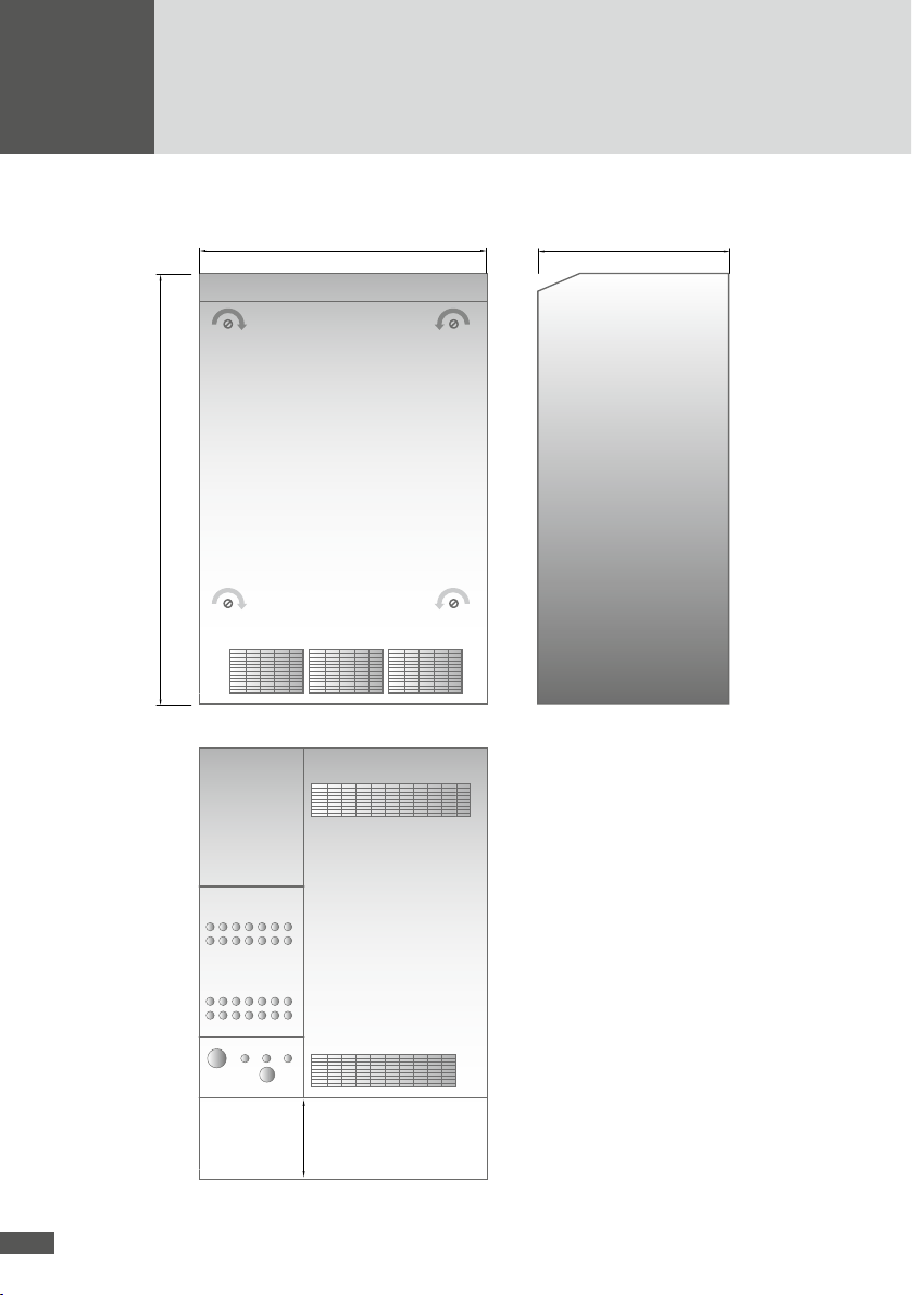
In order to ensure adequate cooling, the back of the unit should be kept free. The dis-
tance to the wall should be at least 30 cm.
If the device is installed in a small plantroom, additional ventilation must be provided
(800 m3/h for SolarMax 20S, 1.200 m3/h for SolarMax 35S). The additional ventilation
may be temperature-controlled. It should be activated when the air temperature in the
plant room exceeds 30 °C.

en
60
In order to avoid unnecessary contamination of the heat sinks and fans, the inverter
should only be operated in environments with minimum dust levels. Rooms with sig-
nicant dust formation (e.g. joinery or metal workshops or similar) are not suitable.
The device is splashproof (IP54) and may be installed outdoors, although it must be
protected from sun and rain.
Due to operational noise emissions (65 dBA @ PRated) installation in living spaces or
ofces is not recommended.
The device must be accessible at least from the front for maintenance and repairs.

61
4.2 Casing dimensions SolarMax 20S/35S
655 mm
Open Open
Open Open
Front view
Supply air
Air out
MC4
+ - PE
COMAC
Exhaust air
Side view
455 mm
1095 mm
Rear view
270 mm

en
62
4.3 Electrical connection
DANGER
Before you start the installation work make sure that all the provided DC and AC feed
lines to the inverter are de-energised. The installation work must be performed by a
qualied electrician who adheres to the recognised rules of electrical installations and
personal health and safety regulations.
AC and DC cables must be suitable for the expected voltages, currents and ambient
conditions (temperature, UV, etc.).
The personal protection regulations must be followed when the inverter is connected
to the AC system.
Ensure that the wires are connected properly.
Double-check the polarity before connecting the MC4 connectors or the DC terminals.
Ensure that the DC cables are laid so as to avoid short-circuits and earth leakage along
their complete length as far as the terminals.
4.3.1 Mains fuses and cable cross-sections
Solarmax 20S 35S
Mains fuses
characteristic D 40 A 63 A
Recommended DC
cable cross-section with
MaxConnect
min. 16 mm2min. 25 mm2
Recommended DC
cable cross-section with
MC4 connectors
min. 2.5 mm2per string min. 2.5 mm2
per string
Recommended cable
cross-section AC Min. 10 mm2Min. 16 mm2
We recommend using larger conductor cross sections in order to minimise line losses.

63
4.3.2 Installation aids
DANGER
Before working on connection terminals the DC and AC supply lines must be discon-
nected.
The terminals are accessible at the front by opening the front panel. To feed the cables
into the terminals release the two retaining screws in the aluminium plate below the DC
disconnecting switch and lower the swing with the string fuses. The terminals and cable
glands are then conveniently accessible. The AC cable must be fed through the M40
cable gland at the rear. The DC connection can be established either via the integrated
MC4 connectors and MC4 sockets or via the M20 cable glands. A third M20 cable gland
is available for an additional earthing cable. A further M25 cable gland can be used for a
maximum of two communication cables.
Purpose Component Cable cross-section
DC input + PE 3x M20 cable gland 6-15 mm
AC output 1x M40 cable gland 20-33 mm
Communication 1x M25 cable gland 5-7 mm
Sealed inserts for all cable glands are included. If the glands are not used, these inserts
must be used in order to ensure that the casing remains splashproof.
Before connecting the strings, ensure that the SolarMax specications (max. voltage
900 V, max. current 10 A/string, polarity) are adhered to over the whole temperature
range of the PV system.
CAUTION
In order to keep the device watertight, individual round cables only may be fed through
the cable glands in combination with the associated rubber insert. Improper installa-
tion may invalidate the warranty.
A cable gland can be used for up to two communication cables if the respective sealing
plugs are removed.

en
64
4.3.3 MC4 terminals
String 1
DC-
A
DC+
String 2
String 3
String 4
String 5
String 6
String 7
String 1
DC-
Max. 900 VDC
Max. 10A / String
DC+
String 2
String 3
String 4
String 5
String 6
String 7
B
Never disconnect under load!
The SolarMax 20S has 7 string terminals (A), the SolarMax 35S has 14 (A+B). Each string
is protected with a fuse. Further information can be found in section 8.3.

65
4.3.4 Terminals SolarMax 20S/35S
UT35UT35UT35
Status signalling contact FK1, FK2
Solar generator
Mains supply 3 x 400 Vac
UT35 UT35 UT35 UT35 UT35
UK5
UK5
PEDC+ DC- PE L1 L2 L3 N
On the AC and DC side wires and strands with a maximum cross-section of 35 mm²can
be used, for the status signalling contact up to 4 mm².
4.3.5 Status signalling contact
The status signalling contact is used for remote monitoring. The potential-free relay con-
tact enables the status of the inverter to be monitored. The contact is connected to the
terminals from the front of the unit (see section 5.1).
The functionality of the status signalling contact can be set in the Settings menu as fol-
lows:
Setting Function
Off The status signalling contact is always open.
Mains
In mains mode the status signalling contact closes immediately and is
opened again with the set delay as soon as the device is no longer in
feed mode.
Error
The status signalling contact closes after the set delay time if a
malfunction, fault or alarm occurs during this time. The relay opens
immediately when the fault is no longer present.

en
66
The electronic monitoring system is supplied from the solar generator, i.e. the status
signalling contact is open during the night and when the DC side is switched off.
The events that may trigger the status signalling contact are listed in section 7.6 “Status
messages”.
Status signalling contact specifications
Contact voltage-free, not protected
max. switching voltage: 250 VAC / 100 VDC
max. switching current: 5 Aeff @ 250 VAC cos phi 1 or 30 VDC
continuous current: 2 Aeff
4.3.6 Communications sockets
The inverters in the SolarMax S series have two RJ45 sockets for data communications
within a MaxComm network:
The left-hand RJ45 socket (RS485/ETHERNET) can be used both as a RS485 and as
an Ethernet interface, the desired function can be toggled in the “Settings” menu. The
Ethernet interface is used for connecting an inverter directly to a PC or to MaxWeb xp.
However, if both sockets are congured as RS485 interfaces, a network of several
RS485 nodes can be set up.
The right-hand RJ45 socket (RS485) is only a RS485 interface. The RS485 interface
is used for connections with other SolarMax inverters or accessories with the Max-
Comm interface.

67
5 Commissioning
After you have tested all the electrical connections and ensured that they are all rmly
secured, the inverter can be commissioned. In particular you must ensure that all the
terminals are tightened, the protective line connection is correctly made and the polarity
of the PV generator is correct.
CAUTION
Before you switch on the inverter, t all the available protective covers.
5.1 Commissioning (Initial Setup)
If the inverter is being commissioned the initial setup will start automatically. This proce-
dure must only be carried out once as part of the commissioning process.
1. Switching on the inverter
Switch on the inverter as described in section 5.2.
2. Selecting the display language
In this step select the language in which the following information and texts in the
display will appear.
3. Selecting the individual country settings
The individual country settings permit making such settings as the required mains
voltage and mains frequency range used in the country of installation. The selection of
the country of installation is independent of the selected display language.
4. Date and time
Set the local time and current date. The date set is stored as the commissioning date
and can be accessed later in the “Information” menu.

en
68
5. Confirming the entries
Now conrm the completion of the initial setup with the button .
CAUTION
The individual country settings (step 3) must be entered with extreme care. Once the
initial setup is completed the selections are permanently set and can no longer be
modied. A wrong selection can lead to problems when operating the inverter and
result in the license to operate being revoked by the local grid operator.
NOTE
You can change all the settings in the initial setup (with the exception of the individual
country settings) at any time in the “Settings” menu.
5.2 Switching on and off
All SolarMax inverters operate fully automatically and maintenance-free. AC and DC cir-
cuit breakers remain switched on at all times. In the morning the SolarMax inverter will
switch on as soon as sufcient power is available and continue to operate until the even-
ing. The electronic system is supplied directly from the solar generator voltage. During the
night the SolarMax inverter is disconnected from the mains.
DANGER
The inverter should only be opened briey for switching on and off. During operation
the device must be fully closed.

69
Switching on:
1. Set the DC circuit breaker to “ON”
2. Set the AC circuit breaker to “ON”
3. Immediately close the SolarMax
front lid
4. Switch on the external AC isolator
(fuse)
The LCD should become active after 20
seconds max. (provided minimum irradi-
ance is available).
After a few seconds the “Overview”
menu will appear on the LCD. The Status
line shows the message “Startup...”
After about 1 minute the SolarMax
inverter will have found the MPP
(maximum power point).
During commissioning, the initial setup
must be completed (section 5.1).
Switching off:
1. Switch off the external AC isolator
(fuse)
2. Open the front lid
3. Set the AC circuit breaker to “OFF”
4. Set the DC circuit breaker to “OFF”
After a short time the LCD will switch
off.
The SolarMax may only be opened for service work and with the AC feed line discon-
nected. During operation the device must be fully closed.
Other manuals for SolarMax S Series
2
This manual suits for next models
2
Table of contents
Other Sputnik Engineering Inverter manuals