SPX FLOW Hankison DH Series User manual
1
PRESSURE-SWING
DESICCANT TYPE
COMPRESSED
AIR DRYERS
7610.479.9 1/22/97
IMPORTANT:
READ PRIOR TO STARTING THIS
EQUIPMENT
A.
UNPACKING
This shipment has been thoroughly checked,
packed and inspected before leaving our plant.
It was received in good condition by the
carrier and was so acknowledged.
1. Check for Visible Loss or Damage. If this
shipment shows evidence of loss or damage
at time of delivery to you, insist that a notation
of this loss or damage be made on the delivery
receipt by the carrier’s agent.
2. Check for Concealed Loss or Damage. When a
shipment has been delivered to you in
apparent good order, but concealed damage is
found upon unpacking, notify the carrier
immediately and insist on his agent inspecting
the shipment. Fifteen days from receipt of
shipment is the maximum time limit for
requesting such inspection. Concealed
damage claims are not our responsibility as
our terms are F.O.B. point of shipment.
B.
MOVING CAUTION:
Do not lift by piping. Use lifting lugs or fork lift.
1. Pressurized devices: This equipment is
a pressure containing device. Do not
exceed maximum operating pressure as
shown on equipment serial number tag.
Make sure equipment is depressurized
before working on or disassembling it
for service.
2. Electrical: This equipment requires
electricity to operate. Install equipment
in compliance with national and local
electrical codes. Standard equipment is
supplied with NEMA 4, 4x electrical
enclosures and is not intended for
installation in hazardous environments.
Disconnect power supply to equipment
when performing any electrical service
work.
3. Breathing Air: Air treated by this
equipment may not be suitable for
breathing without further purification.
Refer to OSHA standard 1910.134 for
the requirements for breathing quality
air.
GENERAL SAFETY
INFORMATION
MODEL RATEDFLOW DESIGNATEDASMODELS
DH-25 25 SCFM 25
DH-45 45 SCFM 45
DH-6000 60 SCFM 60
DH-80 80 SCFM 80
DH-115 115 SCFM 115
DH-165 165 SCFM 165
DH-260 260 SCFM 260
DH-370 370 SCFM 370
DH-450 450 SCFM 450
DH-590 590 SCFM 590
DH-750 750 SCFM 750
DH-930 930 SCFM 930
DH-1130 1130 SCFM 1130
DH-1350 1350 SCFM 1350
DH-1550 1550 SCFM 1550
DH-2100 2100 SCFM 2100
DH-3000 3000 SCFM 3000
DH-4100 4100 SCFM 4100
DH-5400 5400 SCFM 5400
®
Instruction Manual
DH Series
SERVICE DEPARTMENT (724) 746-1100

2
CONTENTS
1.0 DESCRIPTION ............................................................................................................................ 4
1.1 Function...................................................................................................................................... 4
1.2 Description of Operation.......................................................................................................... 5
2.0 INSTALLATION .......................................................................................................................... 6
2.1 Location in a compressed air system...................................................................................... 6
2.2 Minimum & Maximum Operating Conditions .......................................................................... 6
2.3 Mounting..................................................................................................................................... 6
2.4 Piping.......................................................................................................................................... 6
2.5 Electrical connections..............................................................................................................10
2.6 Provisions for purge exhaust ..................................................................................................10
2.7 Initial Desiccant Charge ...........................................................................................................10
3.0 OPERATION ..............................................................................................................................12
3.1 Start-up ......................................................................................................................................12
3.2 Operational check points.........................................................................................................14
3.3 Shut-down ................................................................................................................................ 15
3.4 Loss of power ...........................................................................................................................15
3.5 Design parameters ..................................................................................................................16
3.6 Determining purge and outlet flows .......................................................................................16
3.7 Outlet dew points vs. inlet temperatures ...............................................................................16
4.0 MAINTENANCE .........................................................................................................................18
4.1 Desiccant replacement.............................................................................................................18
4.2 Pilot air filter cartridge replacement (models 370 & larger only) ........................................18
4.3 Fuse Replacement (automatic purge models only)...............................................................19
4.4 Battery replacement (automatic purge models only)...........................................................19
4.5 Test Mode ..................................................................................................................................19
5.0 TROUBLESHOOTING ...............................................................................................................21
NOTE
Supplemental instructions for units supplied with the
optional Automatic Purge Saving System are shown in italics.

3
MINI INSTRUCTIONS
For complete instructions on installation, operation, and maintenance, consult manual.
I . INSTALLATION
1. Install on level surface.
2. Ambient temperature range: 35 to 120°F (1.7 to 49°C) [ if low ambient package supplied: -10 to 120°F (-23 to 49°C) ]
3. Install purge mufflers if shipped separately.
4. Connect air from compressor to inlet.
• Maximum compressed air temperature: 120°F (49°C)
• Maximum compressed air pressure: Refer to serial number tag.
• Minimum compressed air pressure: See section 2.2.1.2 .
5. Connect outlet to air system.
6. Refer to serial number tag for correct voltage. Make electrical connection to terminal strip in electrical enclosure. Standard units: connect
line to position 5, neutral to position 6 and ground to position 7.
Automatic purge saving system: connect wires to positions 2 and 3; ground to position 1.
7. Set controller for 120V or 240V using selector switch.
I I. START UP
1. Set or verify controller settings. See section 3.1.1.
2. SLOWLY pressurize unit.
3. Energize dryer by turning on/off switch on. ("I" is on; "O" is off)
4. Adjust purge air flow rate. Turn purge rate valve until Purge Pressure Gauge reads as shown in the following table.
NOTE: One tower must be purging when setting purge pressure.
III . OPERATIONAL CHECKPOINTS
1. Check that dryer is energized (indicating lights are illuminated)
2. MOISTURE INDICATOR - Indicator should be green (Allow 4 hours after start up for indicator to turn green).
3. TOWER PRESSURE GAUGES -
• Tower on line should read line pressure
• Tower off line should read 2 psig or less while purging. If pressure exceeds 2 psig replace purge muffler elements.
NOTE: An extra set of elements is shipped with dryer.
4. PURGE PRESSURE GAUGE - Verify proper setting.
5. CHECK FOR ALARM CONDITION.
IV . DEPRESSURIZATION
Isolate dryer. Run timer until both tower pressure gauges read 0 psig.
150 psig M.W.P. models
4
Min.
10
Min.
250 psig M.W.P. models
CYCLE
TIME
SETTING
80 79 78 77 76 75 70 64 60 57
4
Min.
10
Min.
—————132123115108102
INLET PRESSURE 60-100 110 120 130 140 150
(psig)
CYCLE
TIME
SETTING
45 43 41 39 37 36
70 66 63 60 58 56
INLET PRESSURE 125 130 135 140 145 150 175 200 225 250
(psig)

4
1.0 DESCRIPTION
1.1 Function
1.1.1 Dryer Dual tower regenerative desiccant dryers are an economical
and reliable way to dry compressed air to dew points below the freezing
point of water (dew points as low as -150°F [1 ppb @ 100 psig, 7.0 kgf/
cm2] are possible) or reduce the moisture content of compressed air when
used in critical process applications.
These dryers continuously dry compressed air by using two identical
towers, each containing a desiccant bed. While one tower is on-stream
drying the compressed air, the other tower is off-stream being regenerated
(reactivated, i.e., dried out). The towers are alternated on- and off-stream
so that dry desiccant is always in contact with the wet compressed air. In
this way a continuous supply of dry air downstream is possible.
Desiccant dryers lower the dew point of compressed air by adsorbing the
water vapor present in the compressed air onto the surface of the
desiccant. Desiccant is a highly porous solid containing extensive surface
area.
Adsorption occurs until the partial pressure of the water vapor in the air
and that on the surface of the desiccant come into equilibrium. As
adsorption occurs, heat is released (referred to as the heat of adsorption)
and is stored in the bed for use during regeneration.
Desiccant is regenerated by driving off (desorbing) the water collected on
its surface. Pressure-swing (also called heatless or heaterless because no
outside heat is added) dryers regenerate by expanding a portion (approxi-
mately 14 - 15% at 100 psig, 7 kgf/cm2) of the dried air to atmospheric
pressure. This “swing in pressure” causes the expanded air to become
very dry (have a very low vapor pressure). This very dry air (called purge
air) plus the stored heat of adsorption allows the moisture to desorb from
the desiccant. The purge air then carries the desorbed water out of the
dryer.
1.1.2 Optional Automatic Purge Saving System
The Automatic Purge Saving System is designed to save energy (purge
air) when pressure-swing dryers are operated at reduced loads.
The patented Purge Saving System operates by monitoring the changes
in temperature within the desiccant beds. These changes in temperature
are the result of heat (thermal energy) that is released when a bed is on-
line drying (heat of adsorption), and the heat that is used when a bed is
off-line being regenerated (heat of desorption).
Themagnitudeofthesechangesintemperatureisanindirectmeasureof
thewatervaporcontentin theairbeingdried.This informationisusedto
determine the time a tower stays on line during the drying cycle.

5
8
1
5C 5D 8
72
61
5A
10A 9A 3A 3B 9B 10B
5B
11
INLET
FIGURE 1A
88
5C 5D
72
6
11
5A 5B
11
10A 9A 3A 10B
9B
3B
INLET
LEGEND
Process Stream
Purge Stream
TOWER4ADRYING: TOWER4BREGENERATING
FIGURE1C
7. Purge Orifice
8. Pressure Relief Valves
9. Purge / Repressurization Valves
10. Purge Mufflers
11. Moisture Indicator
1. Pressure Gauges
2. Purge Pressure Gauge
3. Inlet Switching Valves
4. Desiccant Drying Towers
5. Check Valves
6. Adjustable Purge Rate Valve
FIGURE1B
TOWER4BDRYING: TOWER4AREGENERATING
1.2 Description of Operation
1.2.1 Dryer
(Refer to Figure 1A.)
Compressed air flows through inlet switching valve (3A) to tower
(4A) where the air is dried. After the air is dried it flows through check
valve (5A) and then to the dryer outlet.
A portion of the dry air, the purge stream, branches off from the
main air stream prior to the outlet. The purge stream flow rate is controlled
by the adjustable purge rate valve (6) and the purge orifice (7).
The purge flow, which has been throttled to near atmospheric
pressure, is directed through check valve (5D) to tower (4B). As the purge
flow passes over the desiccant in tower (4B), it removes the water vapor
which was deposited there while the tower was on-line drying. The purge
air then passes through purge and repressurization valve (9B) and purge
muffler (10B) to the atmosphere.
After regeneration, purge and repressurization valve (9B) closes
allowing tower (4B) to repressurize slowly. Adequate repressurization time
is allowed so that tower 4B is fully repressurized before switchover. After a
controlled time period, air inlet switching valve (3B) opens and inlet
switching valve (3A) closes, purge and repressurization valve (9A) then
opens.
(Refer to Figure 1B.)
Tower (4B) is now drying the main air
stream while tower (4A) is being regenerated by the purge air stream. The
operation of the inlet switching and purge and repressurization valves is
sequenced by the control system located in the electrical box.
1.2.2 Optional Automatic Purge Saving System (Refer to Figure 1C)
AssumeTowerAison-linedryingtheairwhiletowerBhasjust
goneoff-linetobe regenerated. Atthe beginningoftower B’s regenera-
tion cycle a temperature measurement is made at position B1. After the
tower has been regenerated, another measurement is made at B1. The
drop in temperature sensed during regeneration is an indirect measure
of the water vapor content of the inlet air. The Purge Saving System’s
microprocessor then uses this information to calculate an allowable
temperature rise in the bed during the drying cycle.
When tower B goes back on-line, a temperature probe at
position B2 measures the initial bed temperature at this point and then
monitors the bed until the calculated temperature rise occurs. The
temperature rise occurs as heat of adsorption is released during the
drying process. The time for the temperature rise to occur depends on
flow rate. At 100% flow the temperature rise takes five minutes, at 50%
flow it takes 10 minutes.
When the calculated temperature rise is reached, the towers
switchwith towerA nowdrying andtower Bbeing regenerated.TowerB
regenerates for 3.9 minutes, repressurizes, and remains idle until it is
called upon for the next drying cycle.
TOWER
4B
TOWER
4A
OUTLET
OUTLET
TOWER
4A TOWER
4B
OUTLET
INLET
A2 B2
TOWER
A TOWER
B
B1
A1

6
Compressor Aftercooler Receiver
Separator Desiccant
Dryer
FIGURE2A
(B & C) PREFILTERS - Adequate filtration is required upstream of the
dryer in order to protect the desiccant bed from contamination. The
following filtration are recommended:
B - Particulate/Gross Liquid Removal
- On heavily contaminated systems
use a gross contaminant filter to remove solids and high inlet liquid
concentrations.
C - Oil Aerosol Removal
-On systems with lubricated compressors, use
an oil removal filter to remove oil aerosols and protect desiccant bed from
oil contamination.
(D) DESICCANT DRYER
(E) AFTERFILTER - To ensure downstream air purity (prevent desiccant
dust from traveling downstream) adequate filtration downstream of the
dryer is required. Typically 1 micron filtration is specified although finer
filtration is available.
OR
Oil Vapor Adsorber
- Use as an afterfilter to remove oil vapor and its
subsequent taste and odor and to protect down-stream components from
solid particles 0.01 micron and larger.
NOTE
By-pass lines and isolation valves are recommended so that maintenance
work can be performed without shutting off the air supply.
2.1 Location in the compressed air system.
NOTE
Air Compressor should be adequately sized to handle air system demands
as well as purge loss. Failure to take this into account could result in
overloading air compressors and/or insufficient air supply downstream.
NOTE
It is desirable to install dryer where compressed air is at the lowest
possible temperature (downstream of aftercoolers) and the highest
possible pressure (upstream of pressure reducing valves) without
exceeding the maximum working pressure.
(Refer to Figure 2A)
(A) AFTERCOOLER/SEPARATOR - Compressed air entering dryer must be
cooled to at least 120°F (49°C). Use aftercooler and separator if higher
temperatures are present.
NOTE
Installation of a refrigerated dryer ahead of a pressure-swing desiccant
dryer does not increase desiccant dryer capacity or reduce purge flow
requirements. However a cooling unit installed ahead of the desiccant
dryer reduces the inlet air temperature and outlet air dew point.
2.0 INSTALLATION
2.2 Minimum & Maximum Operating Conditions
The compressed air supply inlet should be checked periodically to ensure
that equipment design specifications are not exceeded. Normally the
compressor installation includes intercoolers, aftercoolers, separators,
receivers, or similar equipment which adequately pretreat the compressed
air supply in order to avoid excessively high air temperatures and liquid
slugging of downstream equipment.
2.2.1 Compressed air conditions
2.2.1.1 Maximum working pressure:
Refer to dryer Serial Number Tag.
WARNING
Do not operate the dryer at pressures above the maximum
pressure shown on the tag.
2.2.1.2 Minimum working pressures:
150 psig (10.5 kgf/cm2) MWP models -
60 psig (4.2 kgf/cm2) for dryers operated on a 10 minute cycle
80 psig (5.6 kgf/cm2) for dryers operated on a 4 minute cycle
250 psig (17.6 kgf/cm2)MWP models -
125 psig (8.8 kgf/cm2) for dryers operated on a 10 minute cycle
150 psig (10.5kgf/cm2)for dryersoperatedon a4minute cycle.
If lower inlet pressures are encountered, consult factory.
2.2.1.3 Maximum inlet compressed air temperature:
120°F (49°C)
NOTE
If inlet air is higher than 120°F (49°C) the air must be precooled
with an aftercooler.
2.2.2 Ambient temperatures:
Minimum:
Standard units: 35°F (1.7°C)
Units with optional low ambient package: - 10°F (-23°C)
Maximum: 120°F (49°C)
NOTE
If dryer is installed in ambients below 35°F (1.7°C) heat tracing of
the prefilters and inlet piping and valves is necessary to prevent
condensate from freezing. If installing heat tracing, observe electrical
class code requirements for type of duty specified.
2.3 Mounting
Install dryer on a level pad on floor. Holes are provided in the
floor stand base angles for floor anchors if desired.
NOTE
Floor anchors must be used if area is subject to vibrations.
2.4 Piping
2.4.1 Inlet and Outlet connections
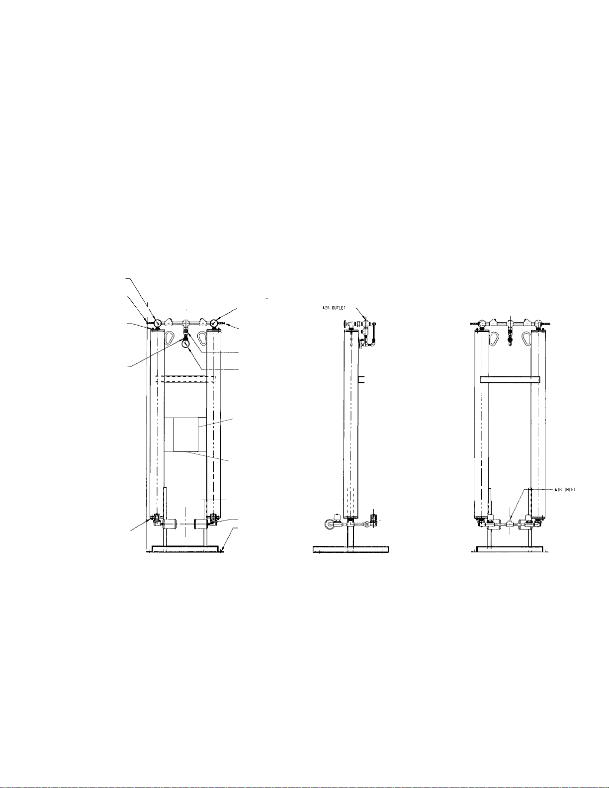
Observe location of inlet and outlet connections as indicated in
Figure 2B, 2C, or 2D and connect inlet and outlet piping.
NOTE
All piping must be supported so as not to bear on the dryers or
filters.
2.4.2 Isolation valves
If isolation valves are installed, it is recommended that gate
valves be used to ensure that dryer is pressurized slowly. This is
particularly true if isolation valves are placed before and after pre-
and afterfilters where rapid pressurization could cause excessive
pressure drop across filter cartridges.
Prefilter(s) Afterfilter
7
Desiccant Drain Port
FRONT VIEW RIGHT SIDE VIEW REAR VIEW
Purge Muffler
3/4" Dia.
Mounting Holes
Desiccant Fill Port
Left Tower Pressure
Gauge
Purge Pressure
Adjustment Valve
Left Tower Pressure
Relief Valve Right Tower Pressure
Gauge
Right Tower
Pressure Relief Valve
Moisture
Indicator
Purge Pressure
Gauge
FIGURE 2B Models 25 through 80
Electrical Entry
(7/8")
Control Panel

8
FIGURE 2C Models 115 through 2100
"G" Air Inlet
Left Tower Pressure
Relief Valve AB
CD
E
L
2" (51mm)
Desiccant Drain Port
"G" Air Outlet K
F
J
H
Right Tower Pressure Relief Valve
3/4" (19mm) Dia. Mounting Holes
Pilot Air Filter (Models 370 & larger)
Moisture Indicator
Right Tower
Pressure Gauge
Control Panel
Electrical Entry
(7/8")
Purge Muffler
Left Tower Pressure Gauge
Purge Pressure Adjustment Valve
Desiccant Fill Port
Purge Pressure Gauge
*
*Models 115 through 260 use solenoid valves. Models 370 and larger use air operated butterfly valves.
**
*
Lifting Lugs

9
FIGURE 2D Models 3000 thru 5400
PA
BM
DC
NE
Right Tower Pressure
Relief Valve
K
FL
J
H
Desiccant Fill Port
Lifting Lugs
Moisture Indicator
Right Tower Pressure
Gauge
Control Panel
Electrical Entry
(7/8")
Purge Mufflers
Desiccant Drain Port
7/8" Dia. Mounting Holes
Lifting Lugs
Left Tower
Pressure Gauge
Purge Pressure
Gauge
Purge Pressure
Adjustment Valve
Pressure
Relief Valve
Left Tower
Air Inlet
Pilot Air Filter
Air Outlet
10
2.5.2.2Automatic PurgeSaving System
Dry contacts for a remote alarm are supplied at terminals 6 and 7.
Maximum contact rating is:
230 VAC - 4.3 amp
115 VAC - 8.7 amp
200 VDC - 0.15 amp
100 VDC - 0.35 amp
50 VDC - 1.2 amp
30 VDC - 4.5 amp
25 VDC - 10 amp
10 VDC - 10 amp
2.5.1.2 Automatic Purge Saving System (Refer to Figure 2F)
Connect wires to terminal strip. Connect line to position 3,
neutraltoposition2andgroundtoposition1. Donotmakeconnections
to terminals labeled with grouding symbol or labeled with RS.
Set the voltage selection switch located at the lower edge of
the control board for the proper supply voltage.
Electricalentryis7/8"dia.holefor1/2"nominalconduitentry.
2.5 Electrical Connections
2.5.1 Power to Unit
NOTE
Check Serial Number Tag for correct voltage.
2.5.1.1 Standard Unit
2.6 Provisions for Purge Exhaust -Purge exhaust must be routed through
the factory supplied mufflers or piped to a remote location.
2.6.1 Purge mufflers - If shipped separately, install purge exhaust
mufflers in the locations shown in Figure 2B, 2C or 2D.
2.6.2 If purge exhaust is piped to a remote location, choose a pipe size
large enough so that back pressure through the piping is not created.
WARNING
Do not operate dryer without one of the above measures. Exhausting air will
result in noise levels above OSHA permissible levels and exhausting gas
could potentially cause harm to persons or property.
2.7 Initial Desiccant Charge -The dryer is shipped complete with desiccant
and ready to operate after piping and electrical connections are made.
POWER REQUIREMENTS
STANDARD CONTROL BOARD
25 THRU 60 120V - 60 Hz, 110V - 50 Hz 34.2 0.53 1.28
240V - 60 Hz, 220V - 50 Hz 34.2 0.27 0.64
80 120V - 60 Hz, 110V - 50 Hz 44.1 0.68 2.70
240V - 60 Hz, 220V - 50 Hz 44.1 0.34 1.35
115 THRU 260 120V - 60 Hz, 110V - 50 Hz 49.4 0.70 3.45
240V - 60 Hz, 220V - 50 Hz 49.4 0.35 1.73
370 THRU 5400 120V - 60 Hz, 110V - 50 Hz 34.6 0.53 1.24
240V - 60 Hz, 220V - 50 Hz 34.6 0.26 0.62
AUTOMATIC PURGE SAVING SYSTEM
25 THRU 60 120V - 60 Hz, 110V - 50 Hz 44.2 0.62 1.37
240V - 60 Hz, 220V - 50 Hz 44.2 0.31 0.68
80 120V - 60 Hz, 110V - 50 Hz 54.1 0.77 2.78
240V - 60 Hz, 220V - 50 Hz 54.1 0.38 1.39
115 THRU 260 120V - 60 Hz, 110V - 50 Hz 59.4 0.78 3.53
240V - 60 Hz, 220V - 50 Hz 59.4 0.39 1.77
370 THRU 5400 120V - 60 Hz, 110V - 50 Hz 44.6 0.61 1.33
240V - 60 Hz, 220V - 50 Hz 44.6 0.30 0.66
AMPS
MODEL WATTS HOLDING INRUSH
2.5.2 Connections for external alarm
2.5.2.1 Standard Unit
Dry contacts for a remote alarm are supplied at terminals 20, 21, 22.
When the unit is energized and no alarms are in effect, continuity should
exist between terminals 20 and 21, with no continuity between terminals
21 and 22. Alarm contact is common for switching failure alarm and
optional high humidity alarm.
Maximum contact rating is:
240 VAC - 5.0 amps
50 VDC - 1.0 amps
Connect wires to terminal strip. Connect line to position 5, neutral
to position 6, and ground to position 7.
Set the voltage selection switch located at the lower edge of the
control board for the proper supply voltage.
Electrical entry is 7/8" dia. hole for 1/2" nominal conduit entry.

11
FIGURE 2F ELECTRICALSCHEMATIC (DRYERSWITHAUTOMATICPURGESAVINGSYSTEM)
Line
Neutral
GND.
Left Tower Lower Thermistor
Left Tower Upper Thermistor
Right Tower Lower Thermistor
Left Tower Pressure Switch
Right Tower Pressure Switch
Right Tower Upper Thermistor
Left Tower Purge & Repressurization Solenoid
Left Tower Switching Solenoid
Right Tower Switching Solenoid
Right Tower Purge & Repressurization Solenoid
FIGURE2E ElectricalSchematic(StandardDryers)
1SOL Energized Indicator (Green)
2SOL Energized Indicator (Green)
3SOL Energized Indicator (Green)
4SOL Energized Indicator (Green)
Left Tower Drying Indicator (Green)
Left Tower Regenerating Indicator (Green)
Right Tower Drying Indicator (Green)
Right Tower Regenerating Indicator (Green)
4 Minute Cycle Mode Indicator (Yellow)
10 Minute Cycle Mode Indicator (Yellow)
Test Mode Indicator (Yellow)
Switching Failure Alarm Indicator (Red)
High Humidity Alarm Indicator (Red)
Purge Economizer 100% Setting Indicator (Yellow)
Purge Economizer 90% Setting Indicator (Yellow)
Purge Economizer 80% Setting Indicator (Yellow)
Purge Economizer 70% Setting Indicator (Yellow)
Purge Economizer 60% Setting Indicator (Yellow)
Purge Economizer 50% Setting Indicator (Yellow)
Purge Economizer 40% Setting Indicator (Yellow)
Purge Economizer 30% Setting Indicator (Yellow)
Alarm-Reset/Selection Mode Switch
Purge
Economizer
DIP Switches
To Solid
State
Timer
and
Control
Circuits
To Solid
State
Timer
and
Control
Circuits
To Solid
State
Timer
and
Control
Circuits
Power Off/On
Switch
Spare Load Connections
Control Circuit Fuse
Solid State Timer and
Control Circuit Step
Down Transformer
120/240 VAC Control
Board Inlet Voltage
Selector Switch
Solenoid Circuit Fuse
Right Tower Inlet
Switching Solenoid
Left Tower Purge/
Repressurization
Solenoid
Right Tower Purge/
Repressurization
Solenoid
Left Tower Inlet
Switching Solenoid
Spare Ground
Connections
Common
Alarm Relay
Common Alarm (See section 2.5.2.1)
Contacts
Right Tower Switching Failure Alarm
Pressure Switch
Left Tower Switching Failure Alarm Pressure
Switch
To Solid State
Timer
and
Control
Circuits
To
Solid
State
Timer
and
Control
Circuits
Customer
Common
Alarm
Connections
Customer
Power
Connections
LEGEND
CR ...................................... CONTROL RELAY
DS ............................................... DIP SWITCH
FU ........................................................... FUSE
L ............................................................. LIGHT
PB .......................................... PUSH-BUTTON
PS ................................. PRESSURE SWITCH
Q ..................TRIAC (SOLID-STATE SWTICH)
SOL ................................... SOLENOID VALVE
SS .................................. SELECTOR SWITCH
SST ................. SOLID-STATE TIMER BOARD
T ............................................ TRANSFORMER
TB ..................................... TERMINAL BLOCK
SW ................................. SELECTOR SWITCH
}Customer Power
Connection

12
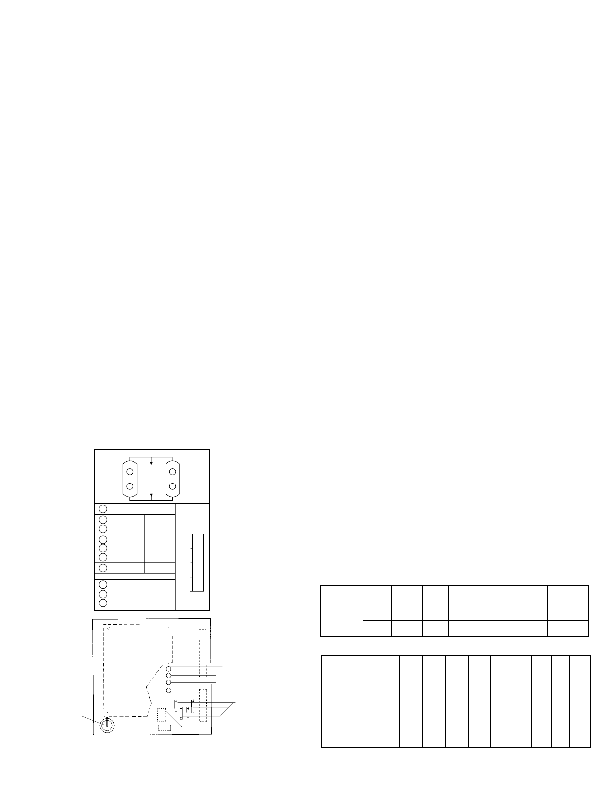
FIGURE 3A
StandardControlPanel
3.0 OPERATION
3.1 Start-up
3.1.1 Controller Settings- Set or verify settings on controller
3.1.1.1 Standard Unit Control Board - NOTE: Make settings with dryer
de-energized.
3.1.1.1.1 Voltage Selection - Set the voltage selection switch located
at the lower edge of the power board for the proper voltage.
3.1.1.1.2 Dip Switch Settings - NOTE: For ON DIP switch is up; OFF
DIP switch is down
1. Select setting for Standard (150 psig, 10.5 kgf/cm2MWP) or
High Pressure (250 psig, 17.6 kgf/cm2MWP) unit (See Serial
Number Tag)
A. Standard - place switch 4 in OFF position
B. High Pressure - place switch 4 in ON position
2. Select Operating Cycle (4 or 10 minute)
A. 10 minute cycle - place switch 5 in OFF position,
switch 6 in ON position
B. 4 minute cycle - place switch 5 in ON position,
switch 6 in OFF position
3. To select Test Mode - place switch 5 and 6 in ON position
4. Purge Economizer Switch Setting - If dryer is operated at less than
maximum flow capacity a reduction in purge air usage may be possible.
Refer to Section 3.5.4 to determine maximum inlet flow capacity at
operating pressure. Divide your actual flow by Maximum Flow to get % of
Maximum Flow. Set switches 1 through 3 as shown
EXAMPLE:
A 60 scfm unit has a Maximum Rated Inlet Flow of 60 scfm @
100 psig. Currently only 30 scfm is used. 30/60 = .50 = 50%. To save
purge air, set Purge Economizer Switch for 50%: switches 1 and 3 are ON,
switch 2 is OFF.
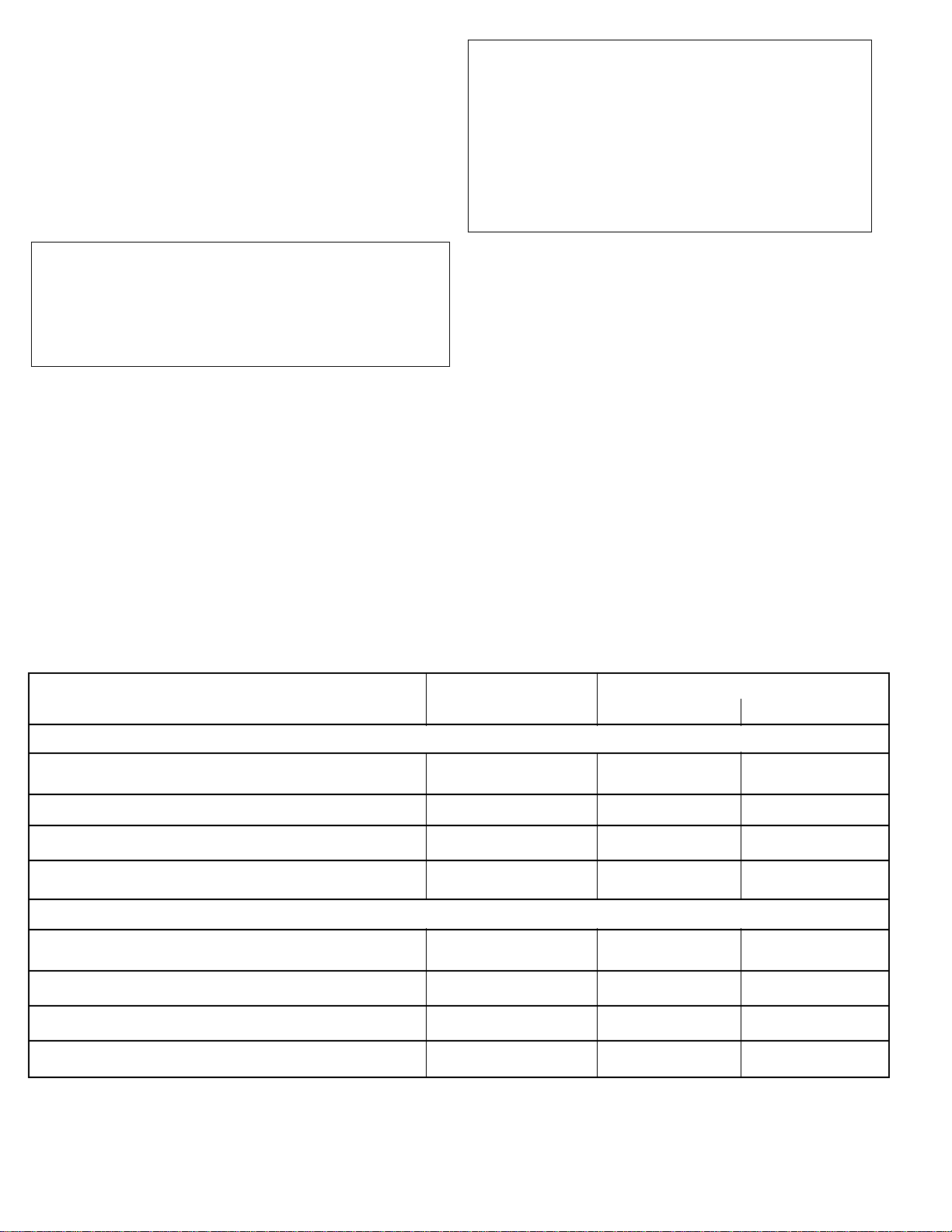
Purge Economizer Setting Standard or High Cycle/Mode Selection
Pressure Selection
Switch No. 1 2 3 4 5 6
Standard 10 minute cycle OFF ON
150 psig OFF
MWP 4 minute cycle ON OFF
High
pressure ON Test mode ON ON
250 psig
MWP
% of
Max.
Flow
100 OFF OFF OFF
90 ON OFF OFF
80 OFF ON OFF
70 ON ON OFF
60 OFF OFF ON
50 ON OFF ON
40 OFF ON ON
30 ON ON ON
NOTE
If full flow is restored, Purge Economizer Switch must be reset for 100%.
• CYCLE MODE • MODO DE CICLO
• MODE CYCLIQUE
Outlet
Salida
Sortie
Inlet
Entrada
Entrée
Drying
Secando
Séchage
Drying
Secando
Séchage
4 Min.
Test Mode
High
Humidity Alarm
Reset/
Selection Mode
• ECONOMIZER SETTING
• DEMANDA PROMEDIO
• REGLAGE POUR MODE ECONOMIQUE
Switching
Failure Alarm
10 Min.
Regenerating
Regenerando
Régénération
Regenerating
Regenerando
Régénération
• TOWER STATUS • ESTADO DE LA TORRE • ETAT DES TOURS
Alarma por Falla en el
Cambio de Torres
Alarme de Non-
Alternance des Tours
Restablecer/
Selector de Ciclo
Commande de Remise/
Sélection de Mode
Alarma por Alta Humedad
Alarme de Haute Humidité
Modo de Prueba
Mode d' Essai
I
O
60 %
50 %
40 %
30 %
100 %
90 %
80 %
70 % 60 %
50 %
40 %
30 %
100 %
90 %
80 %
70 %
Right Inlet Solenoid Energized
Left Purge/Repressurization Solenoid Energized
Right Purge/Repressurization Solenoid Energized
Left Inlet Solenoid Energized
DIP Switches for Economizer Setting,
Standard or HP selection,
Cycle/Mode selection
Alarm Hook-up
Power Hook-up
Voltage Selection
Switch
Soleniod circuit fuse
1.6A 250V
Littlefuse #21701.6
Control circuit fuse
125m A 250V
Littlefuse #218.125
StandardControlPanel
TABLE 3A
13
80 79 78 77 76 75 70 64 60 57
___ ___ ___ ___ ___ 132 123 115 108 102
3.1.1.2
Automatic Purge Saving System Control Board
3.1.1.2.1 Voltage selection - Set the voltage selection
switch located at the lower edge of the power board for the
proper voltage.NOTE:
Make certain that paper insulation in front of battery has been
removed.
3.1.1.2.2
Cycle selection
A cycle selector allows two choices in the fixed cycle mode and
three in the demand cycle mode. Cycle selection is accom-
plished by depressing the cycle selector switch repeatedly until
the light indicating the desired cycle mode illuminates.
1) Fixed cycle mode
10 minute - in this mode the dryer switches towers every 5
minutes. With 100
°
F (38
°
C) inlet air, a -40
°
F (-40
°
C) pres-
sure dew point is produced.
4 minute - In this mode the dryer switches towers every 2
minutes. With 100
°
F (38
°
C) inlet air, a -100
°
F (-73
°
C)
pressure dew point is produced.
(2) Demand Cycle Mode
In this mode the dryer switches when the desiccant bed is
loaded as signalled by a calculated temperature rise. Unit can
be set to produce three outlet dew points, -40
°
F (-40
°
C), 0
°
F
(-17.8
°
C) and 40
°
F (4.4
°
C). NOTE:
Automatic control will begin 1/2 cycle after start-up.
NOTE:
If a cycle change is made while dryer is operating, dryer will
finish previous cycle (right tower drying terminates) before
changing. Indicating light of newly selected mode will blink until
changeover is complete. If it is necessary to begin a new
selection immediately, shut unit off and on. (This is not
recommended if either tower is in the regeneration mode since
rapid repressurization could result.)
NOTE:
If switching to a cycle mode producing a lower dew point (e.g.
0
°
F to -40
°
F [ -17.8 to -40
°
C] ) while dryer is operating, one or
two days of operation may possibly be needed before the new
dew point is achieved.
3.1.2 SLOWLY pressurize dryer to full line pressure (open
inlet valve, outlet valve remains closed).
NOTE
During initial start-up check entire system for leaks. If neces-
sary, depressurize and correct any leaks.
3.1.3 Energize dryer using the power switch located on the
control panel.
NOTE
Standard controller - Switching failure alarm: alarm (light) may
be activated if unit is energized before it is pressurized. To
deactivate alarm, allow dryer to cycle to next step and press
the reset button.
3.1.4 Adjust the purge rate valve.
3.1.4.1 Determine:
1)Maximum working pressure (MWP) of dryer from the dryer
serial number tag
2) Air pressure at inlet to dryer
3) Cycle time setting (4 or 10 minutes)
For units with optional
Automatic Purge Saving System in the demand cycle mode
use the 10 minute setting.
3.1.4.2 Refer to
Table 3B
for proper purge rate pressure
setting at the conditions found in 3.1.4.1
3.1.4.3 Adjust purge rate valve until purge flow indicator
reads required pressure setting.
NOTE
Adjustment must be made while a tower is purging (air
exhausting from muffler).
IMPORTANT
INSUFFICIENT PURGE AIR WILL EVENTUALLY RESULT IN
SATURATION OF DESICCANT BED AND WET AIR DOWN-
STREAM. MAKE CERTAIN THAT CYCLE TIME, PURGE
ECONOMIZER SWITCH, AND PURGE PRESSURE ARE
CORRECTLY SET.
3.1.5 Establish normal flow through dryer (open outlet
isolation valve). Close air by-pass valve if present.
NOTE
When dew points below -40°F (-40°C) are required, the dryer
must be run with an inlet flow rate of less than 50% of maxi-
mum until the desired dew point is attained. Depending on the
initial dryness of the desiccant, this can take as long as 2 to 3
days. This stabilization period is required on initial startup,
after dryer has been shutdown for extended periods of time, or
after dryer maintenance (desiccant change, etc.).
3.1.6 With the inlet pressure to the dryer at its minimum
level, readjust the purge pressure as determined in 3.1.4.
150 psig, 10.5 kgf/cm2M.W.P. models
INLET PRESSURE 60-100 110 120 130 140 150
(psig) 45 43 41 39 37 36
70 66 63 60 58 56
10 Min.
4 Min.
CYCLE
250 psig, 17.6 kgf/cm2M.W.P. models
INLET PRESSURE 125 130 135 140 145 150 175 200 225 250
(psig)
10 Min.
4 Min.
CYCLE
Battery
FIGURE3B
AUTOMATICPURGESAVINGPANEL
LFT. P&R
LFT. INLET SW.
RT. P&R
RT. INLET SW.
Fuses
Voltage Selection
Switch
TOWER STATUS
OUTLET
INLET
DRYING
REGENERATING
DRYING
REGENERATING
4 MINUTES
10MINUTES
40°F/+5°C DEW POINT
0°F/-18°C DEW POINT
-40°F/-40°C DEW POINT
TEST MODE
SWITCHING FAILURE
TEMPERATURE PROBE
RESET
CYCLE SELECTOR AVERAGE
DEMAND
FIXED
CYCLE
DEMAND
CYCLE
MANUAL
CYCLE
ALARMS
100%
75%
50%
25%
0%
TABLE3B- PurgeRatePressureSettings(psig)

14
3.2.1.3 Purge Flow Indicator -Every four hours check the
purgepressure andadjust asrequired.Adjustmentshouldbemade
when the inlet pressure to the dryer is at its minimum level.
NOTE
Adjustmentmustbemadewhileatowerispurging(airexhaust-
ing from muffler).
3.2.1.4 Alarms
Periodically check for flashing red alarm light. Alarm light will
flashifeithertowerfailstopressurizeordepressurizetotherequired
levels at the proper time or if optional high humidity alarm indicates
high exiting dewpoint. NOTE
Alarm will activate if dryer is energized without being pressur-
ized. If this occurs allow dryer to cycle to next step and press reset
button. NOTE
Alarm light will continue to flash even if fault clears. To clear
alarm, press reset button.
NOTE
If the tower being regenerated fails to repressurize, the dryer
will not switch towers. The switching failure alarm will be activated
and the dryer will remain in this mode until the tower repressurizes.
3.2.1.5TowerStatusLights-illuminated lightindicateswhich
tower is on-line (pressurized) or off-line regenerating (depressur-
ized)
3.2.1.6 Tower pressure gauges
3.2.1.6.1 Periodically check tower pressure gauges to verify
that tower pressure gauge of tower on-line reads line pressure and
tower pressure gauge of tower off-line reads below 2 psig.
NOTE
Readoff-linetowergaugewhentowerispurging(airexhausting
from muffler)
3.2.1.6.2 Check mufflers for back pressure
Excessivebackpressuremayresultduetotheaccumulationof
dustinthemuffler. Thissometimesoccursafterstart-upbecauseof
dusting of the desiccant during tower filling and dryer transport.
If the tower pressure gauge of the off-stream tower rises out of
the black area on the gauge dial, muffler elements should be
replaced. A set of purge exhaust muffler replacement elements is
supplied with the dryer.
3.2.2. Units with Automatic Purge Saving
System
3.2.21Powertounit-Checkperiodicallythatthereispower
to the unit (indicating lights illuminated).
3.2.2.2 Moisture Indicator - Every four hours check mois-
tureindicator.Indicatorshouldbe green.Outletrelative humidity
of the desiccant dryer is indicated by the color change humidity
indicator. Green indicates a R.H. below 3% and yellow indicates
a R.H. above 3%. Table 3J (page 17) indicates outlet dew point
whenmoistureindicatorchangesfromgreentoyellowatvarious
inlet temperatures. During start-up the indicator may be yellow,
however, it should begin to change to green within four hours.
3.2.2.3 Purge Flow Indicator -Every four hours check the
purge pressure and adjust as required. Adjustment should be
madewhentheinletpressuretothedryerisatitsminimumlevel.
NOTE
Adjustment must be made while a tower is purging (air
exhausting from muffler).
3.2.2.4 Alarms
3.2.2.4.1 Switching Failure Alarm - The switching failure
alarm operates by sensing tower pressures after tower
changeover. If towers have failed to pressurize or depressurize
to the required levels, an alarm condition exists. The alarm light
blinks while the alarm condition exists. If the alarm condition
clears for two complete cycles, the light will switch to a steady
glow.Depressingtheresetswitchwillextinguishthelight,butwill
not interrupt the drying cycle.
Ifthetowerbeingregeneratedfailstorepressurize,thedryer
will not switch towers. The switching failure alarm will be
activated and the dryer will remain in this mode until the tower
repressurizes.
3.2.2.4.2
Temperature Probe Alarm - (operates in a
demand cycle mode only) This alarm is actuated by a short
circuit, an open circuit, or temperatures below 40
°
F (4.4
°
C) or
above 150
°
F (65.5
°
C). The alarm light blinks while the alarm
conditionexists.Afterthealarmconditionclearsforonecomplete
cycle, the light will switch to a steady glow. Depressing the reset
switch will extinguish the light, but will not interrupt the drying
cycle.
3.2.2.4.3 Dryer Cycle (operates in demand cycle mode
only) Eitheralarmwillcausethecontrollertoautomaticallyswitch
toafixed10minute cycle(cycle modelightwillnotindicate this).
After the alarm condition clears and the light stops blinking,
thecontrollerwillcleartheinternalinformationandswitchbackto
a demand mode. It is not necessary to push the alarm reset for
thedryertoreturntotheselecteddemandcyclemode. However,
to extinguish the alarm light, press the alarm reset button.
NOTE
After an alarm condition clears, the dryer will not return to a
demand cycle mode until the dryer completes two cycles if a
switching failure alarm is experienced or one cycle if a tempera-
ture probe alarm is experienced. This occurs even if the alarm
reset is depressed and the alarm light is extinguished.
3.2.2.4.4
Relay for Remote Alarm
Theremotealarmrelaywillclosewhenanalarmoccursand
remaincloseduntil thealarmclearsand isreset.Therelay does
not cycle as the lights blink.
3. 2 Operational Check Points
3.2.1 Standard Unit
3.2.1.1 Power to unit - Check periodically that there is power to the
unit (indicating lights illuminated).
3.2.1.2 Moisture Indicator - Every four hours check moisture
indicator. Indicator should be green. Outlet relative humidity of the
desiccant dryer is indicated by the color change humidity indicator. Green
indicates a R.H. below 3% and yellow indicates a R.H. above 3%.
Table 3J(page 17) indicates outlet dew point when moisture indicator
changes from green to yellow at various inlet temperatures.
NOTE
During start-up the indicator may be yellow, however, it
should begin to change to green within four hours.

15
150 psig MWP 100% 234 sec.
90% 211 sec.
80% 187 sec.
70% 164 sec.
60% 140 sec.
50% 117 sec.
40% 94 sec.
30% 70 sec.
250 psig MWP 100% 174 sec.
90% 157 sec.
80% 139 sec.
70% 122 sec.
60% 104 sec.
50% 87 sec.
40% 70 sec.
30% 52 sec.
9B Cl OPEN CLOSED CLOSED
6" (2)
ECONOMIZER SWITCH PURGE TIME
SETTING
TIME (Min.)
0 1 2 3 4 5 6 7 8 9 10
3A OPEN CLOSED
3B CLOSED OPEN
9B Cl 6" OPEN (1) Cl CLOSED
9A CLOSED Cl OPEN CLOSED
6" (1)
3.2.2.5 Towerstatuslights- indicatewhenleftandright
towers are drying and regenerating.
3.2.2.6 Valve energized lights
FourLEDsarefurnishedoncontrollertoindicatewhichair
control valves are energized at any particular time
3.2.2.7 Average Demand Meter
The demand meter displays the average demand on the
dryerforthelast 4 cycles.Itisdetermined by dividing 40(time
tocomplete4cyclesatfullflow)bytheactualtimetocomplete
the last 4 cycles.
3.2.2.8 Tower pressure gauges
3.2.2.8.1 Periodically check tower pressure gauges to
verify that tower pressure gauge of tower on-line reads line
pressure and tower pressure gauge of tower off-line reads
below 2 psig. NOTE
Read off-line tower gauge when tower is purging (air
exhausting from muffler)
3.2.2.8.2 Check mufflers for back pressure
Excessive back pressure may result due to the accumu-
lationofdustinthemuffler. Thissometimesoccursafterstart-
upbecauseofdustingof thedesiccantduring towerfillingand
dryer transport.
If the tower pressure gauge of the off-stream tower rises
out of the black area on the gauge dial, muffler elements
should be replaced. A set of purge exhaust muffler replace-
ment elements is supplied with the dryer.
3.2.3 All MODELS - Determine if air control valves are
operating and sequencing correctly.
Refer to Section 1.2 and Figure 1A and 1B for a general
description of operating sequence.
3.2.3.1 Inlet switching and purge/repressurization valves.
1) Tower pressure gauge of tower on-line should read line
pressure. No air should be leaking from purge/repressurization
valve of the on-line tower.
2)Towerpressure gauge oftoweroff-line shouldreadbelow 2
psig while tower is purging. If excessive purge air is exhausting
during purge cycle, inlet valve may have failed to close or a check
valve may be sticking.
3.2.3.2 Check valves
Check valve sticking will result in excessive air discharge
throughamuffler.Ifexcessiveairis dischargedthroughthemuffler
on the left, check if valve 5a or 5d is sticking. If excessive air is
discharged through the muffler on the right, check if valve 5b or 5c
is sticking.
3.2.3.3 Operating Sequence
For dryers with standard controller and dryers with automatic
purge saving system operating on a fixed time cycle-
Figure 3C
and
Table 3C
show valve sequence times when
dryer is operating on a 10 minute cycle.
Figure 3D
and
Table 3D
show sequence times when dryer is operating on a four minute
cycle.
TIME (MIN)
0 1 2 3 4
3A OPEN CLOSED
3B CLOSED OPEN
(1) See table 3C for open times.
VALVE
PRESSURE
9A CLOSED CI OPEN CLOSED
6" (2)
(2) See table 3D for open times.
3.3 Shut Down
3.3.1 Depressurize dryer
3.3.1.1 Open by-pass valve (if one is installed) and close inlet
and outlet isolation valves.
3.3.1.2 Run timer through a tower change cycle until pressure
gauges on both towers read 0 psig.
3.3.2 De-energize dryer
Turn dryer off using on-off switch (indicating lights extin-
guished).
3.4 Loss of Power
Control valves are designed so that upon loss of power the air
dryer is capable of drying air until the desiccant exposed to the air
flow is saturated.
TABLE 3D Purge valve open times for dryers operating on a 4 minute cycle.
VALVE
FIGURE 3D For dryers operating on a 4 minute cycle
TABLE 3C Purge valve open times for dryers operating on a 10 minute cycle.
FIGURE 3C For dryers operating on a 10 minute cycle
150 psig MWP 100% 66 sec.
90% 59 sec.
80% 53 sec.
70% 46 sec.
60% 40 sec.
50% 33 sec.
40% 26 sec.
30% 20 sec.
250 psig MWP 100% 42 sec.
90% 38 sec.
80% 34 sec.
70% 29 sec.
60% 25 sec.
50% 21 sec.
40% 17 sec.
30% 13 sec.
PRESSURE ECONOMIZER SWITCH PURGE TIME
SETTING

16
Determine average outlet flow available by subtracting Aver-
age Purge Flow (APF) found in 3.6.1.2 from the inlet flow to the
dryer. NOTE
Average outlet flow may be used to determine available down-
streamair supplyifastoragevessel(e.g.receivertank)of sufficient
volumeisavailablebetweendryerandpointofairusage.Otherwise
use minimum outlet flow to determine downstream air available.
EXAMPLE
Find maximum inlet flow, maximum and average purge flows,
andminimumandaverageoutletflowsfora60scfmunitwithaMWP
of 150 psig operated at 120 psig on a 10 minute cycle. Dryer will
operate with an inlet air flow of 46 scfm.
Step 1: Find Maximum Inlet Flow @120 psig by multiplying
Maximum Inlet Flow at Rated Conditions from
Table 3E
by Inlet
Pressure Correction Factor for 120 psig from
Table 3F
: 60 x 1.08 =
64.8 scfm.
Step 2: Find Maximum Purge Flow by multiplying Maximum
Inlet Flow at Rated Conditions from
Table 3E
by Maximum Purge
Flow Factor from
Table 3G
: 60 x .162 = 9.7 scfm.
Step 3: Find Average Purge Flow by multiplying Maximum
Inlet Flow at rated conditions from
Table 3E
by Average Purge/
RepressurizationFlowFactorfrom
Table3H:
60x0.097=5.8scfm.
NOTE
At 46scfminletflow,dryerisoperatingat70%ofmaximumflow
found in Step 1: (46/64.8 = 70%.) Average purge flow is based on
Economizer Switch setting of 70%.
Step 4: Find Minimum Outlet Flow available by subtracting
Maximum Purge Flow (Step 2) from inlet flow: 46 - 9.7 = 36.3 scfm.
Step 5: Find Average Outlet Flow available by subtracting
Average Purge Flow (Step 3) from inlet flow: 46 - 5.8 = 40.2 scfm.
3.7 Determining outlet pressure dew point at
various inlet compressed air temperatures:
Theoutletpressuredewpointisdeterminedbythecompressed
air temperature at the inlet to the dryer and cycle time selected ( 4
or 10 minutes). Use
Table 3I
to determine outlet dew points at var-
ious inlet compressed air temperatures and cycle times.
3.5 Verify that dryer is operating within design
parameters
3.5.1 Maximum working pressure:
Refer to Serial Number Tag to determine maximum working
pressure of dryer.
WARNING
Do not operate dryer at pressures above the maximum pres-
sure shown on the tag.
3.5.2 Minimum working pressures:
150 psig, 10.5 kgf/cm
2
MWP models
-
60 psig (4.2 kgf/cm2) for dryers operated on a 10 minute cycle
80 psig (5.6 kgf/cm2) for dryers operated on a 4 minute cycle
250 psig, 17.6 kgf/cm
2
MWP models
125psig(8.8kgf/cm2) for dryersoperatedona 10 minute cycle
150psig(10.5kgf/cm2)fordryersoperatedona4minutecycle.
If lower inlet pressures are encountered, consult factory.
3.5.3 Maximum operating temperature: 120°F (49°C).
3.5.4 Maximum Inlet Flow Capacity
3.5.4.1At100psig(7.0kgf/cm2):Formaximuminletflowat100
psig (7.0 kgf/cm2) refer to
Table 3E.
3.5.4.2Atpressuresotherthan100psig (7.0kgf/cm2):Multiply
inletflowfrom
Table3E
bymultiplierfrom
Table3F
thatcorresponds
to system pressure at inlet to dryer.
3.6 Determining Purge and Outlet Flows:
3.6.1 Purge Flows
3.6.1.1 Maximum Purge Flow.- Maximum Purge Flow (MFP) is
the amount of purge air flowing through the off-stream tower when
the purge/repressurization valve is open. After the purge/
repressurizationvalvecloses,thepurgeflowwillgraduallydecrease
as the off-stream tower repressurizes to line pressure.
For maximum purge flow multiply inlet flow at rated conditions
from
Table 3E
by Maximum Purge Flow Factor from
Table 3G
that
correspondstothedryerMWP,CycleTimeSetting,andairpressure
at inlet to dryer. For dryers supplied with the optional Automatic
PurgeSavingSystemoperatingintheDemandCycleMode,use10
minutes as the cycle time.
3.6.1.2 Average Purge Flow - For dryers with the standard
control board and dryers with the Automatic Purge Saving System
operating in the fixed cycle mode:
The Average Purge Flow (APF) is the actual amount of flow
used during the entire purge/repressurization cycle. It includes the
maximumpurgeflow(MFP)foraportionofthepurge/repressurization
time and the volume of air used for repressurization, averaged over
the cycle time.
To determine average purge flow, multiply maximum inlet flow
atratedconditionsfrom
Table3E
byAveragePurge/Repressurization
Flow Factor from
Table 3H
that corresponds to the dryer Maximum
Working Pressure, Inlet Pressure, Cycle Time Setting, and Econo-
mizer Switch Setting.
3.6.2 Outlet Air Flow
3.6.2.1 Minimum Outlet Flow
Determine minimum outlet flow available from dryer by sub-
tractingMaximum PurgeFlow(MFP)foundin3.6.1.1frominletflow
to the dryer.
3.6.2.2 Average Outlet Flow - For dryers with the standard
control board and dryers with the Automatic Purge Saving System
operating in the fixed cycle mode:

17
4.2 4.9 5.6 6.3 7.0 7.7 8.4 8.8 9.1 9.8 10.5 12.3 14.1 15.8 17.6
0.65 0.74 0.83 0.91 1.00 1.04 1.08 1.10 1.12 1.16 1.20 1.29 1.37 1.45 1.52
60 70 80 90 100 110 120 130 140 150 125 150 175 200 225 250
100% 0.141 0.142 0.143 0.143 0.144 0.139 0.135 0.131 0.128 0.125 0.133 0.125 0.119 0.114 0.111 0.108
90% 0.127 0.128 0.129 0.130 0.130 0.126 0.122 0.119 0.116 0.113 0.120 0.113 0.108 0.104 0.101 0.099
80% 0.114 0.114 0.115 0.116 0.117 0.113 0.110 0.107 0.104 0.102 0.108 0.102 0.098 0.094 0.092 0.090
70% 0.100 0.101 0.101 0.102 0.103 0.100 0.097 0.095 0.092 0.091 0.096 0.091 0.087 0.084 0.082 0.081
60% 0.086 0.087 0.088 0.088 0.089 0.087 0.084 0.082 0.081 0.079 0.083 0.079 0.076 0.074 0.073 0.072
50% 0.073 0.073 0.074 0.075 0.076 0.073 0.072 0.070 0.069 0.068 0.071 0.068 0.066 0.064 0.063 0.063
40% 0.059 0.060 0.060 0.061 0.062 0.060 0.059 0.058 0.057 0.056 0.058 0.056 0.055 0.054 0.054 0.054
30% 0.045 0.046 0.047 0.047 0.048 0.047 0.046 0.046 0.045 0.045 0.046 0.045 0.044 0.044 0.044 0.045
100% 0.147 0.149 0.151 0.153 0.155 0.151 0.148 0.145 0.143 0.141 - 0.141 0.137 0.135 0.134 0.134
90% 0.134 0.136 0.137 0.139 0.141 0.138 0.135 0.133 0.131 0.129 - 0.129 0.127 0.125 0.125 0.125
80% 0.120 0.122 0.124 0.125 0.127 0.124 0.122 0.120 0.119 0.118 - 0.118 0.116 0.115 0.116 0.116
70% 0.106 0.108 0.110 0.112 0.114 0.111 0.110 0.108 0.107 0.106 - 0.106 0.105 0.105 0.106 0.107
60% 0.093 0.095 0.096 0.098 0.100 0.098 0.097 0.096 0.095 0.095 - 0.095 0.095 0.095 0.097 0.098
50% 0.079 0.081 0.083 0.084 0.086 0.085 0.084 0.084 0.084 0.084 - 0.084 0.084 0.085 0.087 0.089
40% 0.065 0.067 0.069 0.071 0.072 0.072 0.072 0.072 0.072 0.072 - 0.072 0.074 0.075 0.078 0.080
30% 0.052 0.053 0.055 0.057 0.059 0.059 0.059 0.060 0.060 0.061 - 0.061 0.063 0.065 0.068 0.071
INLET psig
PRESSURE kgf/cm2
MULTIPLIER
TABLE 3G Maximum Purge Flow Factor
DRYER MWP 150 psig 250 psig
INLET PRESSURE (psig) 60-100 110 120 130 140 150 125 150 175 200 225 250
0.175 0.168 0.162 0.156 0.151 0.146 0.214 0.196 0.184 0.172 0.163 0.155
0.249 0.239 0.230 0.221 0.215 0.207 - 0.326 0.304 0.286 0.270 0.257
CYCLE
TIME 10 minute
4 minute
10
MINUTE
CYCLE
INLET TEMP. °F 35 40 50 60 70 80 90 100 110 120
°C 1.7 4.4 10.1 15.6 21.1 26.7 32.2 37.8 43.3 48.9
°F -34 -28 -22 -16 -10 -4 3 9 15 21
OUTLET P.D.P. °C -36.7 -33.4 -30.0 -26.7 -23.4 -20.0 -16.1 -12.8 -9.5 -6.1
INLET TEMP. °F 35 40 50 60 70 80 90 100 110 120
°C 1.7 4.4 10.1 15.6 21.1 26.7 32.2 37.8 43.3 48.9
. OUTLET P.D.P. °F -75 -70 -65 -60 -55 -50 -45 -40 -35 -30
10 MIN. CYCLE °C -59.4 -56.7 -53.9 -51.1 -48.3 -45.6 -42.8 -40.0 -37.2 -34.4
OUTLET P.D.P. °F -149 -145 -138 -130 -122 -115 -108 -100 -92 -85
4 MIN. CYCLE °C -100.6 -98.3 -94.4 -90.0 -85.6 -81.7 -77.8 -73.3 -68.9 -65.0
TABLE 3J Outlet pressure dew points at moisture indicator color
change
250 psig
ECONOMIZER
SWITCH
SETTING
ECONOMIZER
SWITCH
SETTING
DRYER MWP 150 psig
4
MINUTE
CYCLE
TABLE 3H Average Purge/Repressurization Flow
Factor
TABLE 3I Outlet pressure dew points for dryers supplied with Activated Alumina Desiccant
60 70 80 90 100 110 120 125 130 140 150 175 200 225 250
TABLE 3F Inlet Pressure Correction Factor
MODEL 25 45 60 80 115 165 260 370 450 590 750 930 1130 1350 1550 2100 3000 4100 5400
Inlet @ 100 psig
(7.0 kgf/cm2) 25 45 60 80 115 165 260 370 450 590 750 930 1130 1350 1550 2100 3000 4100 5400
(scfm) (1) (2)
(1) Convert scfm to metric units as follows: 1 scfm = 1.717m3n/h.
(2) "Performance data obtained and presented in accordance with CAGI standard ADF200 - Methods for rating and testing."
Conditions for rating air dryers are: 100 psig (7.0 kgf/cm2) and 100oF (37.8oC)saturated inlet air, and a maximum 5 psi (.4 kgf/cm2) pressure drop. Actual pressure drop for
all units is less than 3 psi at rated conditions.
TABLE 3E Maximum Inlet Flow at Rated Conditions
INLET PRESSURE (psig)

18
FILL
PLUG
DRAIN
PLUGS
FIGURE4A
TABLE 4A Amount of desiccant required for complete change (lb)
MODEL 25 40 60 80 115 165 260 370 450 590
ACTIVATED ALUMINA 48 48 72 106 182 182 316 452 528 710
MODEL 750 930 1130 1350 1550 2100 3000 4100 5400
ACTIVATED ALUMINA 926 1172 1468 1766 2064 2592 3930 4920 7750
4.0 MAINTENANCE
WARNING
The heatless desiccant dryer is a pressure containing device.
Depressurize before servicing. (See Section 3.3)
4.1 Desiccant Replacement
NOTE
The use of the correct replacement desiccant is necessary for
proper dryer operation. Never use hygroscopic salts of the type
commonly used in “deliquescent” type dryers.
4.1.1 Frequency of desiccant replacement
Desiccantshouldbereplacedwhenevertherequired dewpoint
cannot be maintained while the dryer is being operated within its
design conditions and there are no mechanical malfunctions. Refer
to section 5.0 for troubleshooting hints.
NOTE
Desiccantlifeisdeterminedbythequalityoftheinletair.Proper
filtering of the inlet air will extend the life of the desiccant.
Typically desiccant life is 3 to 5 years.
4.1.2 Procedure for Desiccant Charge Replacement
4.1.2.1 Depressurize and de-energize the dryer. (See section
3.3) 4.1.2.2Removethefillanddrain
plugsfromdesiccanttoweranddrain
the spent desiccant. Place a con-
tainer at the base of the vessel to
collect the desiccant. If necessary
tap the sides of the vessels with a
rubber mallet to loosen desiccant.
4.1.2.3 Replace the drain plug
usingteflontapesealantor equiva-
lent.4.1.2.4 Fill the desiccant drying
tower as full as possible with dry
desiccant. Do not tamp desiccant.
4.1.2.5 Replace the fill plug us-
ingteflon tapesealant orequivalent.
4.1.2.6 Repeat this procedure
for the other drying tower.
4.1.3 Insuring desiccant dryness
4.1.3.1 Replacement desiccant is shipped in air tight contain-
ers. Keep the covers on these containers tightly closed until use to
avoidmoisturecontamination.Ifdesiccantisexposedtoairitcanbe
heatedinan oven at400°F(204°C) forfourhours before use,orthe
procedure in 4.1.3.2 can be used.
4.1.3.2 If the dryer is not refilled with dry desiccant, it will be
necessarytooperatethedryerwithaninletflowrateoflessthan50%
of maximum to dry the desiccant. To do this, set the Economizer
Switch for 100%, and the purge pressure for 45 psig. (3.2 kgf/cm2)
NOTE
4.2.2.1 Remove the filter bowl.
4.2.2.2 Clean the filter bowl.
4.2.2.3 Remove the old filter element and discard. Also discard
the small O-ring that seals the filter to the filter assembly head.
4.2.2.4 Insert small replacement O-ring on top of replacement
filter element and replace filter element.
4.2.2.5 After making sure large O-ring in filter head is in place,
reassemble filter bowl to filter head.
4.3 Fuse Replacement
4.3.1 Standard Units Only:
4.3.1.1 Fusesarelocatedonboardinelectricalenclosure. See
Figure 3A or 3B.
FIGURE4B
HEAD
HEAD "O" RING
CARTRIDGE "O" RING
CARTRIDGE
BOWL
4.2 Pilot Air Filter - Element Replacement -
Models 370 scfm and larger
4.2.1Frequencyofreplacement-Pilotairfiltercontainsafilter
elementwhichshouldbechanged yearlyor soonerifpressure drop
across cartridge prevents valves from actuating. Pilot air pressure
must not drop below 60 psig (4.2 kgf/cm2).
4.2.2 Procedure for cartridge replacement.
WARNING
THE FILTER IS A PRESSURE CONTAINING DEVICE. DE-
PRESSURIZE DRYER BEFORE SERVICING. (SEE SECTION
3.3)
19
4.3.2 Fuse Replacement
Only one of the "Valve Power" and one of the "Control
Power" fuses should be installed at any time.
4.3.2.1 Use 1/8 amp fuse in positions 1 & 2
4.3.2.2 Use 1.6 amp fuse in positions 3 & 4.
4.3.2.3 Positions 1 & 4 take 5 mm x 20 mm size.
4.3.2.4 Positions 2 & 3 take 1/4" x 1 1/4" size.
4.3.2.5 Place fuses in positions 2 & 3 or 1 & 4 only. Do not
place fuses in all four positions.
STEP WHAT
NUMBER OCCURS L L R R L P/R L IN R P/R R IN T T B B
LT RT LT RT P/R IN P/R IN L R L R
Start D D LP LP C O C O
1 R IN closes D - LP LP C O C C E X
2 (1) R P/R opens D R LP <2 C O O C E E X
3 No change D R LP <2 C O O C E E X
4 (2) (3) R P/R closes D - LP REP C O C C E X
5 R IN opens D D LP LP C O C O
6 L IN closes - D LP LP C C C O E X
7 (1) L P/R opens R D <2 LP O C C O E E X
8 No change R D <2 LP O C C O E E X
9 (2) (3) L P/R closes - D REP LP C C C O E X
POS. 1 POS.4
POS.2 POS. 3
4.5.2 Test Mode - Automatic Purge Saving System
4.5.2.1 Press cycle selector switch until Test Mode Light
illuminates. This change will not be acknowledged by the controller
until the present cycle is completed (right tower drying terminates)
oruntilthecontroller is de-energizedandre-energized. NOTE: Do
not de-energize dryer unless both towers are at line pressure.
4.5.2.2 Use the alarm reset switch to step through cycle in the
order shown in 4B.
4.5.2.3 Theaveragedemandmeterwillfunctionasavoltmeter
monitoring the voltage from the thermistors. The thermistor being
monitored is indicated in Table 4B. A 0% reading indicates a short
circuit and a 100% reading indicates an open circuit. A curve
relating the demand meter reading to thermistor temperature is
shown in Figure 4C, page 20.
SOLENOID/TERMINALS THERMISTOR
TOWER STATUS VALVE POSITION ENERGIZED BEING CHECKED
(light illuminated) (automatic purge
saving system)
MODE PRESSURE
4.4 Battery replacement
Controller contains a battery which requires replacement
every3to4years. If thebatteryisdeadandthepoweristurned
off and back on, a 10 minute fixed cycle will be selected by
default.
4.5.2.4 After troubleshooting is completed, reset the cycle
selector to the desired position. Use the reset switch to manually
stepthroughthedryeroperatingsequenceuntiltheleft towerdrying
light is illuminated and the reset switch cannot be used to step
through the cycle. At this point, the dryer is on automatic control.
Verify that the right tower depressurizes and repressurizes auto-
matically before leaving the dryer.
If the dryer is switched from the test mode and the cycle is not
completed using the reset switch, the controller will automatically
step through the test mode at a rate of one step every 50 seconds
until the cycle is completed. Normal operation will then resume.
NOTE
Changesinthecycleselectorareonlyacknowledgedwhenthe
present cycle is completed. If in the test mode, continue to step
through dryer operating sequence until left tower drying begins.
NOTES:
(1)Closepurgerate valve during thissteptocheck for any valve leaks. Noairshouldexhaust through the muffler. Ifairisexhausting through the muffler,
check all valves for leaks. After testing for leaks or fixing any leaks, be sure to open the purge pressure valve and reset the purge pressure.
(2) Do not go to the next step until the tower is repressurized.
(3) Switching failure alarm circuit is energized during this step (alarm light should flash until pressure exceeds 40 psig).
CODES:
R IN
- Right inlet valve D - Drying E - Energized
R P/R - Right purge/repressurization valve R - Regenerating TL -Top left
L IN - Left inlet valve LP - Line Pressure TR - Top right
L P/R - Left purge/repressurization valve <2 - Less than 2 psig BL - Bottom left
LT - Left tower REP - Repressurizing BR - Bottom right
RT - Right tower C - Closed
O - Open
Test Mode
4.5 Test Mode
4.5.1 Test Mode - Standard Control Panel
4.5.1.1 To select test mode, de-energize dryer and place DIP
switches 5 and 6 in ON position.
4.5.1.2 Use Reset/Selection Mode switch to step through
cycle in the order shown in Table 4B.
4.5.1.3 When finished (it is recommended that all 9 steps are
completed) de-energize dryer, reset DIP switches 5 and 6 to the
cycle time (4 or 10 minutes) desired, and re-energize.
NOTE
Do not de-energize dryer unless both towers are at line
pressure.
TABLE 4B

20
160
140
120
100
80
60
40
20
0 10 20 30 40 50 60 70 80 90 100
TEMPERATURE RANGE VERSUS AVERAGE DEMAND
THERMISTOR TEMPERATURE RANGE (F)
AVERAGE DEMAND READING
FIGURE4C
This manual suits for next models
19
Table of contents
Other SPX FLOW Dehumidifier manuals

SPX FLOW
SPX FLOW HBP Series User manual

SPX FLOW
SPX FLOW FLEX Series User manual

SPX FLOW
SPX FLOW Hankison HPR Series User manual

SPX FLOW
SPX FLOW Deltech ZP Series User manual

SPX FLOW
SPX FLOW Deltech FLEX Series User manual

SPX FLOW
SPX FLOW DFX 1.1 User manual

SPX FLOW
SPX FLOW Delair EtsilineCommPact User manual

SPX FLOW
SPX FLOW HES Series User manual

SPX FLOW
SPX FLOW Pneumatic Products SHA Series User manual


