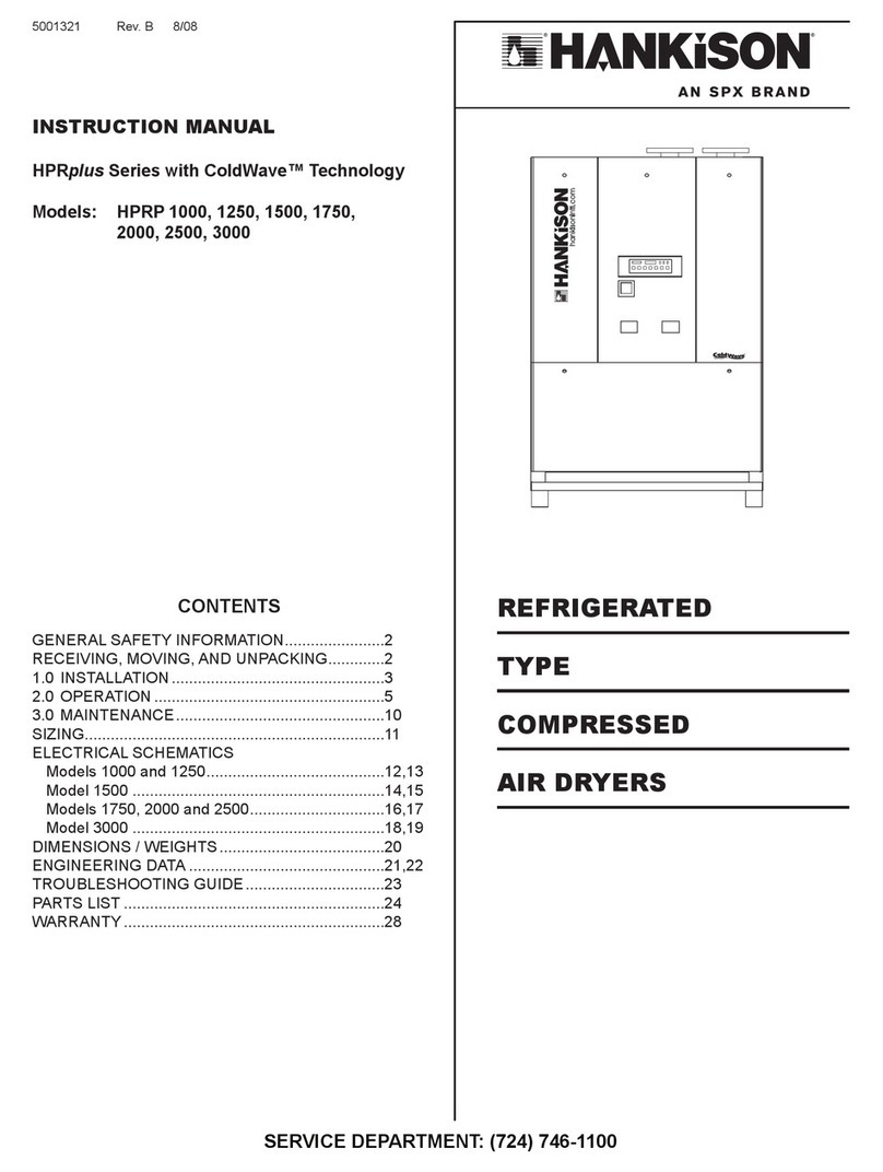
SPX FLOW HES Series User manual

HES Series
Refrigerated Type Compressed Air Dryers
FORM NO.: 7427751 REVISION: 11/2017 READ AND UNDERSTAND THIS MANUAL PRIOR TO OPERATING OR SERVICING THIS PRODUCT.
INSTRUCTION MANUAL
Water Cooled
MODELS RATED
FLOW
HES3750
HES5000
HES6250
3750 SCFM
5000 SCFM
6250 SCFM
HES7500
HES8750
HES10000
7500 SCFM
8750 SCFM
10000 SCFM
HES11250
HES12500
11250 SCFM
12500 SCFM
Air Cooled
MODELS RATED
FLOW
HES3150AC
HES4200AC
HES5250AC
3150 SCFM
4200 SCFM
5250 SCFM
HES6300AC
HES7350AC
HES8400AC
6300 SCFM
7350 SCFM
8400 SCFM
HES9450AC
HES10500AC
9450 SCFM
10500 SCFM

CONTENTS
1.0 GENERAL SAFETY INFORMATION ........................................................ 1
2.0 RECEIVING, MOVING, AND UNPACKING .............................................. 1
3.0 INSTALLATION ......................................................................................... 6
4.0 OPERATION ............................................................................................ 9
5.0 MAINTENANCE ........................................................................................ 19
6.0 TROUBLESHOOTING GUIDE.................................................................. 21
7.0 REFERENCE
Sizing......................................................................................................... 24
Engineering Data Tables ........................................................................... 25-26
Dryer Set Point Tables............................................................................... 27-28
Dryer Alarm Tables .................................................................................... 29-30
Controller Screen Shots
Dryer Status Screens............................................................................. 31
Module Status Screens.......................................................................... 32
Alarm History Screens........................................................................... 33
Energy Savings Screens ....................................................................... 34
Dryer Scheduler Screens....................................................................... 35
Dryer Setting Screens............................................................................ 36-37
Network Setting Screens ....................................................................... 38
Factory Setting Screens ........................................................................ 39
8.0 DRAWINGS: WATER-COOLED UNITS
General Arrangement
Models 3750 and 5000 .......................................................................... 40
Models 6250 and 7500 .......................................................................... 41
Models 8750 and 10000 ........................................................................ 42
Models 11250 and 12500 ...................................................................... 43
Electrical Schematic
Refrigeration Dryer ................................................................................ 44-47
Instrumentation Option .......................................................................... 48-50
575V option............................................................................................ 51
9.0 DRAWINGS: AIR-COOLED UNITS
General Arrangement
Models 3150 and 4200 .......................................................................... 52
Models 5250 and 6300 .......................................................................... 53
Models 7350 and 8400 .......................................................................... 54
Models 9450 and 10500 ........................................................................ 55
Electrical Schematic
Refrigeration Dryer ................................................................................ 56-60
Instrumentation Option .......................................................................... 61-63
575V option............................................................................................ 64
10.0 REPLACEMENT PARTS
Cabinet Panels.......................................................................................... 65
Water-Cooled Units ................................................................................... 66-67
Air-Cooled Units ........................................................................................ 68-69
NOTES:................................................................................................................ 70
WARRANTY......................................................................................................... 71

1
2.0 RECEIVING, MOVING, AND UNPACKING
2.1 RECEIVING
This shipment has been thoroughly checked, packed and
inspected before leaving our plant. It was received in good
condition by the carrier and was so acknowledged.
Check for Visible Loss or Damage. If this shipment shows
evidence of loss or damage at time of delivery to you,
insist that a notation of this loss or damage be made on
the delivery receipt by the carrier’s agent.
2.2 UNPACKING
Check for Concealed Loss or Damage. When a shipment
has been delivered to you in apparent good order, but
concealed damage is found upon unpacking, notify the
carrier immediately and insist on his agent inspecting
the shipment. Concealed damage claims are not our
responsibility as our terms are F.O.B. point of shipment.
2.3 MOVING
In moving or transporting dryer, do not tip dryer onto its
side.
2.4 STORAGE/SHUT DOWN
The dryer should not be stored outside (either
packaged or unpackaged) or exposed to the weather. Damage
to the electrical and control components may result.
IMPORTANT: If the dryer is shut down in below freezing
temperatures, the water-cooled condenser may freeze and
cause permanent damage. The condenser must be drained
when the unit is shut down.
IMPORTANT: Do not store dryer in temperatures above 130°F
(54°C).
1.0 GENERAL SAFETY INFORMATION
1.1 PRESSURIZED DEVICES:
This equipment is a pressure containing
device.
• Do not exceed maximum operating
pressure as shown on equipment
serial number tag.
• Make sure equipment is depressurized before working
on or disassembling it for service.
1.2 ELECTRICAL:
This equipment requires electricity to
operate.
• Install equipment in compliance with all
applicable electrical codes.
• Standard equipment is supplied with electrical
enclosures not intended for installation in hazardous
environments.
• Disconnect the power supply to the equipment when
performing any electrical service work.
1.3 BREATHING AIR:
• Air treated by this equipment may
not be suitable for breathing without
further purication.
Refer to applicable standards and
specications for the requirements
for breathing quality air.

2
FEATURES AT A GLANCE:
WATER-COOLED UNITS
DETAIL A
MASTER CONTROL ELECTRICAL ENCLOSURE
WITH CUSTOMER INTERFACE
MASTER CONTROL KEYPAD
QUARTER TURN LATCH
MASTER ENCLOSURE POWER
DISCONNECT SWITCH
LED TEXT DISPLAY
A
RIGID GROOVE COUPLINGS
CONDENSATE DRAIN
CONNECTION 3/8-FPT
SEPARATOR ACCESS
(NO PANEL REMOVAL REQUIRED)

3
DETAIL C
SWING PANEL ACCESS
(PANEL HINGES LOCK OPEN @115°)
DETAIL B
MODULE POWER
DISCONNECT SWITCH
QUARTER TURN LATCH FOR
ELECTRICAL ENCLOSURE ACCESS
POWER ON LED (GREEN)
ALARM LED (RED)
WARNING LED (YELLOW)
QUARTER TURN LATCHES FOR
SWING PANEL ACCESS
B
MODULE ELECTRICAL ENCLOSURE
MOUNTED ON SWING PANEL
FLOOR MOUNT BRACKET
GROOVED FLANGE ADAPTERS

4
FEATURES AT A GLANCE:
AIR-COOLED UNITS
DETAIL A
MASTER CONTROL ELECTRICAL ENCLOSURE
WITH CUSTOMER INTERFACE
MASTER CONTROL KEYPAD
QUARTER TURN LATCH
MASTER ENCLOSURE POWER
DISCONNECT SWITCH
LED TEXT DISPLAY
A
SEPARATOR ACCESS
(NO PANEL REMOVAL REQUIRED)
GROOVED FLANGE ADAPTERS
AIR COOLED CONDENSER
(ONE PER MODULE)
VARIABLE SPEED FANS
QUICK DISCONNECT NO-LOSS
REFRIGERATION FITTINGS
CONDENSATE DRAIN
CONNECTION 3/8-FPT

5
DETAIL C
SWING PANEL ACCESS
(PANEL HINGES LOCK OPEN @115°)
DETAIL B
MODULE POWER
DISCONNECT SWITCH
QUARTER TURN LATCH FOR
ELECTRICAL ENCLOSURE ACCESS
POWER ON LED (GREEN)
ALARM LED (RED)
WARNING LED (YELLOW)
QUARTER TURN LATCHES FOR
SWING PANEL ACCESS
FLOOR MOUNT BRACKET
RIGID GROOVE COUPLINGS
MODULE ELECTRICAL ENCLOSURE
MOUNTED ON SWING PANEL

6
3.3 ADDITIONAL INSTALLATION PROCEDURE FOR AIR
COOLED CONDENSER OPTION
A. Air Condenser – Locate air condenser and set condenser
with brackets on top of unit. Locate brackets per drawing
on following page and bolt to frame using Qty (4) 3/8-16
Bolt’s supplied.
B. Install discharge and liquid refrigerant piping per drawing.
Turn until nut bottoms using quick links. Please note piping
is charged with refrigerant.
C. Wire junction box per wiring schematic reference drawing
for air cooled units in manual.
3.4 MODULE INSTALLATION
A. Identify customer-to-dryer connection requirements.
NOTE: Inlet and outlet headers on the dryer offer dual
installation capability. Either end of the header (inlet or
outlet) may be equipped with an adaptor ange or blind
ange for the customer connection.
B. Install a grooved adapter ange to the inlet header of the
module which is to be connected to the customer inlet con-
nection. (Refer to the General Arrangement drawing for
the specic model in Section 8 or 9 of this manual for the
correct Inlet location.)
C. Install a grooved adapter ange to the outlet header of the
module which is to be connected to the customer outlet
connection. (Refer to the General Arrangement drawing
for the specic model in Section 8 or 9 of this manual for
the correct Outlet location.)
D. NOTE: Be sure that the leveling feet are seated completely
against the bottom of the cabinet prior to setting the module.
This will allow the greatest range of adjustment.
Utilizing a standard oor jack and the fork channels con-
structed in the base pan of each module, align the module
with the grooved adapter ange on the inlet connection
with the customer’s inlet connection.
Level and plumb the module by adjusting the leveling feet
at the bottom of each module.
IMPORTANT: READ PRIOR TO STARTING THIS EQUIPMENT
3.0 INSTALLATION
3.1 LOCATION
A. For typical placement in a compressed air system, see
drawing.
B. Air compressor intake – Locate the air compressor so that
contaminants potentially harmful to the dryer (e.g. ammo-
nia) are not drawn into the air system.
C. The dryer should be installed in a moderately heated, well
ventilated area. Avoid locations immediately adjacent to
cold exterior windows or walls, or adjacent to high tem-
perature ovens or boilers.
D. The dryer should be installed in the air system at the high-
est air pressure possible (e.g. before pressure reducing
valves).
E. The dryer should be installed in the air system at the cool-
est compressed air temperature possible.
F. Clearances:
Service clearance should be a minimum of 48 inches
(1220 mm) on all sides to allow adequate space for access
and maintenance. Recommended overhead clearance is
36 inches (914mm) from top of cabinet for water cooled
unit and top of condenser for air cooled unit.
G. Standard units are designed to operate in ambient:
Water-cooled: 40 to 130°F (4 to 54°C)
Air-cooled: 40 to 110°F (4 to 43°C).
H. Dryer is designed to operate at all altitudes - no adjust-
ment for altitude is required.
I. The installation of a exible connection prior to the dryer is
recommended to prevent possible damage from vibration.
NOTE: Outdoor installation – Standard units are designed for
indoor installation. Contact manufacturer if installing outdoors.
3.2 MOUNTING
Mount the dryer on a level solid surface.
Aftercooler
Separator
Dryer
Compressor

7
C
D
DETAIL C
CONDENSER INLET
(GAS LINE)
SEE NOTES!
CONDENSER OUTLET
(LIQUID LINE)
SEE NOTES!
DETAIL D
ATTACH SUPPORT STRUCTURE WITH
BOLT & WASHER UP THROUGH FROM
INSIDE AND WASHER & LOCKNUT ON
TOP, OUTSIDE UNIT (2 PLACES)
CONNECT CONDENSER
POWER HARNESS
TO CORRESPONDING
JUNCTION BOX
TERMINALS
ATTACH REAR SUPPORT STRUCTURE
W/ BOLT & WASHER DOWN THROUGH
FROM OUTSIDE AND WASHER &
LOCKNUT INSIDE UNIT. (2 PLACES)
MAIN POWER ENTRY IS
IN CONDENSER ENCLOSURE
AT BOTTOM CENTER
NOTES:
1. After installing the condenser unit assembly to the top
of the module, apply appropriate amount of approved
refrigerant tting lubricant to the condenser lines quick
connect ttings (Detail ‘C’).
2. Connect line assemblies between condenser and dryer
module (Detail ‘C’).
3. Use back up wrenches when tightening ttings to prevent
twisting lines, making sure the ttings are fully seated.
4. After the lines are connected, use a leak detection device
to assure there are no leaks at the connections.
INSTALLATION PROCEDURE FOR AIR COOLED CONDENSER

8
E. Connect the module to the customer’s inlet connection.
Tighten ange bolts.
NOTE: Tighten ange bolts to customer outlet connec-
tion if grooved adapter ange to the outlet header is also
installed on module.
F. CRITICAL ASSEMBLY NOTE! The permissible gap
range between the ends of the adjacent inlet and outlet
headers is 0 - 0.25 inches. Also, based on the tolerance
of the modules the module cabinets may either be ush or
will provide a gap. Check each module cabinet gap prior
to tightening the header couplings in place and set the gap
to be consistent if so desired.
Repeat step D for installing the remaining modules to the
dryer. Connect the modules together using couplings
provided. Tighten bolts.
NOTE: The modules are numbered and should be
installed in sequential order. If piping begins on the right
side, start with the highest numbered module rst and
Cooling Water System – Hose Labeling Matrix
Flow Rate Module Position Module Tie Wrap Label Description
3750 - 5000 scfm
M2 Z
M2 Cooling Water Inlet Wrap - MI
Cooling Water Outlet Wrap - MO
ZCooling Water Inlet Wrap - ZI
Cooling Water Outlet Wrap - ZO
Flow Rate Module Position Module Tie Wrap Label Description
6250 - 7500 scfm
M3 Y Z
M3 Cooling Water Inlet Wrap - MI
Cooling Water Outlet Wrap - MO
YCooling Water Inlet Wrap - YI
Cooling Water Outlet Wrap - YO
ZCooling Water Inlet Wrap - ZI
Cooling Water Outlet Wrap - ZO
Flow Rate Module Position Module Tie Wrap Label Description
8750 - 10000 scfm
M4 X Y Z
M4 Cooling Water Inlet Wrap - MI
Cooling Water Outlet Wrap - MO
XCooling Water Inlet Wrap - XI
Cooling Water Outlet Wrap - XO
YCooling Water Inlet Wrap - YI
Cooling Water Outlet Wrap - YO
ZCooling Water Inlet Wrap - ZI
Cooling Water Outlet Wrap - ZO
Flow Rate Module Position Module Tie Wrap Label Description
11250 - 12500 scfm
M5 W X Y Z
M5 Cooling Water Inlet Wrap - MI
Cooling Water Outlet Wrap - MO
WCooling Water Inlet Wrap - WI
Cooling Water Outlet Wrap - WO
XCooling Water Inlet Wrap - XI
Cooling Water Outlet Wrap - XO
YCooling Water Inlet Wrap - YI
Cooling Water Outlet Wrap - YO
ZCooling Water Inlet Wrap - ZI
Cooling Water Outlet Wrap - ZO
work down. Piping that begins on the left side will start
with the lowest numbered module and work up. Interior
modules can be identied by their open framework on
each side of the module.
G. Install blind anges on module headers not previously
tted with grooved adapter anges.
H. Secure the dryer to the oor with the oor mounting
brackets provided on the Master Module and the end
Dryer Module.
3.5 WATER CONNECTIONS (Standard Water Cooled Unit)
A. Connect the cooling water supply to the cooling water inlet
connection of the dryer.
B. Connect the cooling water return line to the cooling water
outlet connection of the dryer.
NOTE: It is recommended to add water inlet and outlet
temperature and pressure gauges to the water piping at
the dryer inlet and outlet connections.

9
4.0 OPERATION
Basic theory of operation: The dryer uses digital scroll technol-
ogy to achieve energy savings. The refrigeration compres-
sor has a unique mechanism that allows it to be completely
“unloaded”.
This is accomplished internally, using a piston to “pull” the
upper scroll apart from the lower scroll. This stops the com-
pression of the refrigerant and dramatically reduces energy
consumption. The compressor motor continues to spin, provid-
ing lubrication to the mechanism.
At the rated compressed air ow rate, the compressor runs
fully loaded. At reduced ow rates, the control system
determines the amount of unloading required to maintain a
constant outlet dew point.
NOTE: The compressor sound changes noticeably between
the loaded and unloaded state, this occurs every ten to forty
seconds.
4.1 MINIMUM/MAXIMUM OPERATING CONDITIONS
A. Inlet air pressure: 30 / 232 psig (2 /16 barg)
B. Inlet air temperature: 40 / 130°F (4 / 54°C)
C. Ambient temperature:
Water Cooled: 40 / 130°F (4 / 54°C)
Air Cooled: 40 / 110°F (4 / 43°C)
4.2 START-UP
(Refer to the Control Panel illustration on the following page
and Controller Screen Shots in Section 8 for control panel as-
sistance)
A. Energize the dryer by turning on the red/yellow disconnect
switches at the main display control panel and at each
module. A green power on light will illuminate and blink on
each enclosure.
IMPORTANT: Energize for 24 hours before starting the
dryer! All disconnect switches must be turned on. Never
use the disconnect switches to shut down the dryer for
an extended period of time (except for repair). Failure to
follow these instructions may result in a non-warrantable
compressor failure.
B. Programming the Dryer Controller (MEM)
Select and press the keypad button associated with each
programming function. Use the Up and Down arrow buttons
to scroll through the list of sub-menu choices. Press the Enter
button to view the sub-menu that is displayed. Press ESC to
return to the Main Menu.
1. Setting Date & Time
a. Press the Clock keypad button to display the Date/
Time Set-up Menu.
NOTE: This menu can also be displayed by pressing
the Set-up Menu keypad button.
b. Use the ‘Up’ and ‘Down’ arrow buttons to set year (10
to 99 representing 2010 to 2099). Press ‘Enter’ to
accept new value.
c. Use the ‘Up’ and ‘Down’ arrow buttons to set month (01
to 12). Press ‘Enter’ to accept new value.
NOTE: Each module is shipped from the factory with the
necessary water piping included. A strainer and water
regulating valve is supplied on each dryer module.
C. Open the swing panels that hold the module electrical
enclosures.
D. Connect the labeled water lines of each module to the
barbed ttings of the mating lines located on the module to
its left. See the table below for hose identication.
3.6 ELECTRICAL CONNECTIONS
IMPORTANT: Use copper supply wires
only.
A. The dryer is designed to operate on
the voltage, phase, and frequency
listed on the serial number tag.
B. Water Cooled Units: The electrical supply connection for
each dryer module is made in the junction box located at
the top of each module. Refer to the dryer serial tag or the
electrical data table for the maximum overcurrent protec-
tion to be used with each dryer module circuit.
NOTE: The dryer is designed to run continuously
and should NOT be wired to cycle on/off with the air
compressor.
C. Air Cooled Units: The electrical supply connection for
each dryer module is made in the junction box located at
the end of the air cooled condenser. Refer to the dryer
serial tag or the electrical data table for the maximum
overcurrent protection to be used with each dryer module
circuit.
NOTE: The dryer is designed to run continuously and should
NOT be wired to cycle on/off with the air compressor.
3.7 CONDENSATE AND ELECTRONIC
DEMAND DRAIN (EDD) CONNECTIONS
A. Connect customer supplied condensate
line to condensate drain connection lo-
cated at the bottom left of the dryer.
NOTE: Condensate may contain oil.
Comply with applicable laws concerning
proper disposal.
B. All dryer modules are supplied with one EDD as standard.
Modules with the additional (optional) oil removal lters
are supplied with two additional EDDs each.
C. From the back of each module, remove the panel and
connect each drain line to the adjacent module using the
push-to-connect drain connections.
3.8 COMMUNICATION CONNECTIONS
A. Open the swing panels that hold the module electrical
enclosures.
B. Locate the communications cable located at the top right
corner of the module.
C. Plug the cable in to the connector located on the back of
the swing panel of the module to its right.

10
d. Use the ‘Up’ and ‘Down’ arrow buttons to set day (01
to maximum for the month and year selected). Press
‘Enter’ to accept new value.
e. Use the ‘Up’ and ‘Down’ arrow buttons to set hours (00
to 23). Press ‘Enter’ to accept new value.
f. Use the ‘Up’ and ‘Down’ arrow buttons to set minutes
(00 to 59). Press ‘Enter’ to accept new value.
g. Use the ‘Up’ and ‘Down’ arrow buttons to set seconds
(00 to 59). Press ‘Enter’ to accept new value.
2. Setting Schedule
a. Press the Scheduler keypad button.
b. Use the ‘Up’ and ‘Down’ arrow buttons to select desired
“Day of week ”. Press ‘Enter’ to accept new value.
c. Use the ‘Up’ and ‘Down’ arrow buttons to set hour (00
to 23). Press ‘Enter’ to accept new value.
NOTE: If the hour setting is ‘IGNORE’, Press ‘Enter’
again.
d. Use the ‘Up’ and ‘Down’ arrow buttons to set minutes.
Press ‘Enter’ to accept new value. Repeat steps a
through c as needed.
3. Setting Hours To Service
a. Press the Set-up Menu keypad button.
b. Use the Up and Down arrow buttons to scroll to the
Service Interval Set-Up menu. Press ‘Enter’ to view
the sub-menu.
c. Use the ‘Up’ and ‘Down’ arrow buttons to scroll through
the range of permissible values (1000 to 8000) before
service reminder is initiated. Press ‘Enter’ to accept
new value. (Only hours that refrigeration compressor is
operating are counted).
NOTE: All dryers contain an integral 3 micron lter.
As the lter element accumulates solid contaminants,
differential pressure increases. Solid particulate
load in the compressed air supply will determine
frequency of service. Typically element change out is
recommended at least annually.
4. Energy Cost
a. Press the Set-up Menu keypad button.
b. Use the Up and Down arrow buttons to scroll to the
Energy Cost Set-Up menu. Press ‘Enter’ to view the
sub-menu.
c. Use the ‘Up’ and ‘Down’ arrow buttons to select the
desired currency ($ or €). Press ‘Enter’ to accept new
value.
d. Use the ‘Up’ and ‘Down’ arrow buttons to set the
energy cost. Press ‘Enter’ to accept new value.
5. Event or Alarm History
a. Press the Event keypad button.
b. Use the Event keypad button to scroll through the
Event (Alarm History) menu.
c. Use the ‘Up’ and ‘Down’ arrow buttons to scroll through
the last twenty (20) alarms beginning with the most
recent alarm.
NOTE: The number at the end of the top line identies
which of the past twenty alarms is being displayed.
C. Starting the Dryer
IMPORTANT: The dryer must be energized 24 hours before
starting the refrigeration compressor.
NOTE: It is recommended that dryer be started 15 minutes
before compressed air ow begins.
1. Begin cooling water ow prior to starting water cooled
units. Turn air condenser disconnect on for air cooled
units.
NOTE: If a module must be shut down, refer to section
5.1 – “Procedure for Shutting Down a Single Module”
located on page 18.
2. Check for proper electrical voltage.
3. Conrm the module ball valves located behind the electri-
cal enclosure swing panel are open, unless the module is
intended to be off-line.
4. The dryer may be operated in either manual or scheduled
mode.
a. Manual mode - This mode is initiated by pushing the
On/Off button. The modules will run continuously and
will not be turned on and off by the controller. All of the
modules will be started when pushing the On/Off from
the home screen. Individual modules can be started
from the module screen. Push the module button and
push the On/Off button. Scroll to the next module by
using the module button then push the On/Off button.
Continue this until all the desired modules are started.
From the home screen, scroll down one screen to see
the status of each module.
Module Status Modes: S - standby, R - running,
A - alarm, D - disconnected
Once turned On, the dryer and modules will begin will
begin to register a load percentage value. The mod-
ules can also be turned off at the dryer home screen or
individually at the module screen.
b. Schedule mode - This mode allows the user to set a
weekly schedule for when the dryer will be on and off.
See 4.2.B.2 for setting the schedule. Each module can
be selected to operate on the preset schedule. Press
the module key and press Enter to select either Manual
Standby or Scheduled Standby.
NOTE: The dryer may be returned to the manual mode
at any time using the ‘On/Off’ button. MANUAL FIXED or
MANUAL STANDBY will appear on display panel. To reinstitute
Schedule, go to the module screen and push the Enter button.
NOTE: The dryer will not automatically restart in the event
of a power failure. Consult factory if it is desired to have the
equipment automatically restart after power interruption.
NOTE: The dryer will run in FIXED mode for a brief period
then switch over to PID control.
5. Slowly pressurize the unit air side by opening the inlet
isolation valve. Check for air leaks.
6. After 15 minutes, slowly open the outlet isolation valve and
close the air by-pass valve (if equipped).

11
RESET
I 2 3
ESC
$
RESET
I 2 3
ESC
$
1
2
3
4
5
CONTROL PANEL
1. Alarm / Service Light
2. Warning Light
3. Power-on Light
4. Operator Interface Display
5. Operator Keypad
6. Disconnect Switch
6
Operator Keypad
Dryer Status I 2 3 Module Status Setup Up Arrow
Scheduler Graph Event Down Arrow
$Energy Savings Mute Date/Time Setup Enter
Shift
ESC
Escape/Cancel
RESET
Reset On/Off

12
D. Operating Check Points
1. Check that no alarms or warnings exist. The green light
only should be illuminated on the module and master elec-
trical enclosures. A yellow light indicates a warning which
indicates an issue that needs to be addressed. The dryer
will continue to operate. A red light indicates an alarm and
will shut down the affected module. Refer to the Trouble-
shooting Guide for addressing Warnings and Alarms.
2. The home screen will indicate an operating load % value
for the dryer. Press the module button and scroll through
each module to conrm the status is NORMAL and a load
% value for the module is displayed.
3. Check the operating parameters of the modules by select-
ing the modules using the arrow keys to scroll through the
list.
4. If equipped with the optional instrumentation package, ad-
ditional parameters can be viewed on the home screen by
using the arrow keys.
E. Using the RS-485 Port Connector (J3)
This connector provides RS-485 compatible signals from the
internal master microprocessor. Using jumpers on the headers
supplied near the connector (J1 and J2), 120 ohm termination
resistors can be connected and the system can be connected
for either two-wire or four-wire operation (half or full duplex). To
connect the termination resistors, install jumpers on J1 in the
direction shown by the white bars printed above the connector.
If the jumpers are removed no termination of the RS-485 bus is
in effect. Usually, these jumpers must be in position for proper
operation of the bus.
J2 (located above J1) contains the two-wire/four-wire jumpers. If
the jumpers are in place, the circuit is set up for two-wire opera-
tion. If the jumpers are removed the circuit is set up for four-wire
operation. Selection of jumper settings must be determined by the
customer’s system. The jumpers are supplied as standard and
are installed as shown at the factory. Be sure to set the jumpers
properly for your system.
RS-485 Pinout
Following is the pinout for J3, the RS-485 communications
connector.
1 TX-
2 TX+
3 RX+
4 RX-
5 Data Enable - asserted high (+5 VDC) when transmitting
6 100 Ohms to Ground
7 TX- (spare)
8 TX+ (spare)
When connected in two-wire mode, the bus wires may be
connected to pins 1 & 2, Pins 3 & 4 or pins 7 & 8. Also note
that when in two-wire mode, one termination resistor jumper
should be removed to prevent the termination from being too
low in value. It may be stored on the top set of pins on J1.
Those pins are not connected. Please make sure that your
connections are properly made. This connector is an 8-pin
RJ45 connector. Mating connectors are not supplied. The
electrical signals supplied by this connector are TIA/EIA-485A
compliant. A good cable should be used to transmit signals
such as Belden 3109A or equivalent.
Communication Parameters:
RS-485 Parameters
Baud Rate 19200
Data Bits 8
Parity None
Stop Bits 1
Flow Control None
Slave ID 1

13
Modbus Registers
Page 1 of 3
Holding Register
Reference Address Name Units Description
40001 0x0000 DRYER_STATUS Status ID Status ID for the dryer
40002 0x0001 ALARM_STATUS Flag Bits Alarm ag bits
40003 0x0002 WARNING_STATUS Flag Bits Warning ag bits
40004 0x0003 SERVICE_STATUS Flag Bits Service ag bits
40005 0x0004 DRYER_LOAD Percent Dryer load as a percentage of full load
40006 0x0005 AVG_DAILY_LOAD Percent Average daily dryer load
40007 0x0006 AVG_MONTHLY_LOAD Percent Average monthly dryer load
40008 0x0007 INLET_AIR_TEMP Celsius Inlet air temperature
40009 0x0008 WATER_TEMP / AMBIENT_TEMP Celsius Water Cooled - Cooling water temperature / Air Cooled - Ambient air temperature
40010 0x0009 OUTLET_AIR_PRESSURE PSIG Outlet air pressure
40011 0x000A WATER_PRESS / RESERVED PSIG Water Cooled - Cooling water pressure / Air Cooled - Reserved
40012 0x000B ANNUAL_SAVINGS Integer Projected annual energy savings in dollars / euros
40013 0x000C CUMULATIVE_SAVINGS Integer Total cumulative energy savings in dollars / euros
40017 0x0010 MOD_1_STATUS Status ID Status ID for module #1
40018 0x0011 MOD_1_ALARMS Flag Bits Alarm ag bits
40019 0x0012 MOD_1_WARNING Flag Bits Warning ag bits
40020 0x0013 MOD_1_SERVICE Flag Bits Service ag bits
40021 0x0014 MOD_1_LOAD Percentage Module load as a percentage of full load
40022 0x0015 MOD_1_PV PSIG Process value
40023 0x0016 MOD_1_SUCTION_TEMP Celsius Suction temperature
40024 0x0017 MOD_1_SEPARATOR_TEMP Celsius Separator temperature
40025 0x0018 MOD_1_DISCHARGE_TEMP Celsius Discharge temperature
40026 0x0019 MOD_1_SUCTION_PRESS PSIG Suction pressure
40027 0x001A MOD_1_DISCHARGE_PRESS PSIG Discharge pressure
40028 0x001B MOD_1_SERVICE_TIMER Hours Module service timer
40029 0x001C MOD_1_TOTAL_TIMER Hours Module total operating timer
40030 0x001D MOD_1_ALARM_PHRASE1 Phrase ID Alarm phrase 1
40031 0x001E MOD_1_ALARM_PHRASE2 Phrase ID Alarm phrase 2
40032 0x001F MOD_1_ALARM_PHRASE3 Phrase ID Alarm phrase 3
40033 0x0020 MOD_2_STATUS Status ID Status ID for module #2
40034 0x0021 MOD_2_ALARMS Flag Bits Alarm ag bits
40035 0x0022 MOD_2_WARNING Flag Bits Warning ag bits
40036 0x0023 MOD_2_SERVICE Flag Bits Service ag bits
40037 0x0024 MOD_2_LOAD Percentage Module load as a percentage of full load
40038 0x0025 MOD_2_PV PSIG Process value
40039 0x0026 MOD_2_SUCTION_TEMP Celsius Suction temperature
40040 0x0027 MOD_2_SEPARATOR_TEMP Celsius Separator temperature
40041 0x0028 MOD_2_DISCHARGE_TEMP Celsius Discharge temperature
40042 0x0029 MOD_2_SUCTION_PRESS PSIG Suction pressure
40043 0x002A MOD_2_DISCHARGE_PRESS PSIG Discharge pressure
40044 0x002B MOD_2_SERVICE_TIMER Hours Module service timer
40045 0x002C MOD_2_TOTAL_TIMER Hours Module total operating timer
40046 0x002D MOD_2_ALARM_PHRASE1 Phrase ID Alarm phrase 1
40047 0x002E MOD_2_ALARM_PHRASE2 Phrase ID Alarm phrase 2
40048 0x002F MOD_2_ALARM_PHRASE3 Phrase ID Alarm phrase 3

14
Modbus Registers
Page 2 of 3
Holding Register
Reference Address Name Units Description
40049 0x0030 MOD_3_STATUS Status ID Status ID for module #3
40050 0x0031 MOD_3_ALARMS Flag Bits Alarm ag bits
40051 0x0032 MOD_3_WARNING Flag Bits Warning ag bits
40052 0x0033 MOD_3_SERVICE Flag Bits Service ag bits
40053 0x0034 MOD_3_LOAD Percentage Module load as a percentage of full load
40054 0x0035 MOD_3_PV PSIG Process value
40055 0x0036 MOD_3_SUCTION_TEMP Celsius Suction temperature
40056 0x0037 MOD_3_SEPARATOR_TEMP Celsius Separator temperature
40057 0x0038 MOD_3_DISCHARGE_TEMP Celsius Discharge temperature
40058 0x0039 MOD_3_SUCTION_PRESS PSIG Suction pressure
40059 0x003A MOD_3_DISCHARGE_PRESS PSIG Discharge pressure
40060 0x003B MOD_3_SERVICE_TIMER Hours Module service timer
40061 0x003C MOD_3_TOTAL_TIMER Hours Module total operating timer
40062 0x003D MOD_3_ALARM_PHRASE1 Phrase ID Alarm phrase 1
40063 0x003E MOD_3_ALARM_PHRASE2 Phrase ID Alarm phrase 2
40064 0x003F MOD_3_ALARM_PHRASE3 Phrase ID Alarm phrase 3
40065 0x0040 MOD_4_STATUS Status ID Status ID for module #4
40066 0x0041 MOD_4_ALARMS Flag Bits Alarm ag bits
40067 0x0042 MOD_4_WARNING Flag Bits Warning ag bits
40068 0x0043 MOD_4_SERVICE Flag Bits Service ag bits
40069 0x0044 MOD_4_LOAD Percentage Module load as a percentage of full load
40070 0x0045 MOD_4_PV PSIG Process value
40071 0x0046 MOD_4_SUCTION_TEMP Celsius Suction temperature
40072 0x0047 MOD_4_SEPARATOR_TEMP Celsius Separator temperature
40073 0x0048 MOD_4_DISCHARGE_TEMP Celsius Discharge temperature
40074 0x0049 MOD_4_SUCTION_PRESS PSIG Suction pressure
40075 0x004A MOD_4_DISCHARGE_PRESS PSIG Discharge pressure
40076 0x004B MOD_4_SERVICE_TIMER Hours Module service timer
40077 0x004C MOD_4_TOTAL_TIMER Hours Module total operating timer
40078 0x004D MOD_4_ALARM_PHRASE1 Phrase ID Alarm phrase 1
40079 0x004E MOD_4_ALARM_PHRASE2 Phrase ID Alarm phrase 2
40080 0x004F MOD_4_ALARM_PHRASE3 Phrase ID Alarm phrase 3
40081 0x0050 MOD_5_STATUS Status ID Status ID for module #5
40082 0x0051 MOD_5_ALARMS Flag Bits Alarm ag bits
40083 0x0052 MOD_5_WARNING Flag Bits Warning ag bits
40084 0x0053 MOD_5_SERVICE Flag Bits Service ag bits
40085 0x0054 MOD_5_LOAD Percentage Module load as a percentage of full load
40086 0x0055 MOD_5_PV PSIG Process value
40087 0x0056 MOD_5_SUCTION_TEMP Celsius Suction temperature
40088 0x0057 MOD_5_SEPARATOR_TEMP Celsius Separator temperature
40089 0x0058 MOD_5_DISCHARGE_TEMP Celsius Discharge temperature
40090 0x0059 MOD_5_SUCTION_PRESS PSIG Suction pressure
40091 0x005A MOD_5_DISCHARGE_PRESS PSIG Discharge pressure
40092 0x005B MOD_5_SERVICE_TIMER Hours Module service timer
40093 0x005C MOD_5_TOTAL_TIMER Hours Module total operating timer
40094 0x005D MOD_5_ALARM_PHRASE1 Phrase ID Alarm phrase 1
40095 0x005E MOD_5_ALARM_PHRASE2 Phrase ID Alarm phrase 2
40096 0x005F MOD_5_ALARM_PHRASE3 Phrase ID Alarm phrase 3

15
Modbus Registers
Page 3 of 3
Holding Register
Reference Address Name Units Description
40129 0x0080 NUM_MODULES Integer Number of installed modules
40130 0x0081 SERVICE_INTERVAL Hours Service interval
40131 0x0082 ENERGY_COST Integer Energy cost in 1/100th Dollars / Euros per kWh
40132 0x0083 CONDENSER_TYPE Integer Condenser type selection (0=Water Cooled, 1=Air Cooled)
40133 0x0084 MODBUS_ADDRESS Integer Modbus drop number
40134 0x0085 AUDIBLE_ALARM Boolean Audible alarm enabled
40135 0x0086 WATER_PRESSURE_SP PSIG Low cooling water pressure alarm set point
40136 0x0087 WATER_TEMPERATURE_SP Celsius High cooling water temperature alarm set point
40137 0x0088 INLET_TEMPERATURE_SP Celsius High inlet air temperature alarm set point
40138 0x0089 OUTLET_PRESSURE_SP PSIG Low outlet air pressure alarm set point
40139 0x008A AMBIENT_TEMPERATURE_SP Celsius High ambient air temperature alarm set point
40140 0x008B MOD_1_TYPE Integer Module type (0=None, 1=6HP, 2=10HP)
40141 0x008C MOD_2_TYPE Integer Module type (0=None, 1=6HP, 2=10HP)
40142 0x008D MOD_3_TYPE Integer Module type (0=None, 1=6HP, 2=10HP)
40143 0x008E MOD_4_TYPE Integer Module type (0=None, 1=6HP, 2=10HP)
40144 0x008F MOD_5_TYPE Integer Module type (0=None, 1=6HP, 2=10HP)

16
Modbus Register Details
Page 1 of 3
Dryer Status Flags
Register 40001
Bit Mask Description
0 0x0001 Module 1 status (0 = not installed, 1 = installed)
1 0x0002 Module 2 status (0 = not installed, 1 = installed)
2 0x0004 Module 3 status (0 = not installed, 1 = installed)
3 0x0008 Module 4 status (0 = not installed, 1 = installed)
4 0x0010 Module 5 status (0 = not installed, 1 = installed)
5 0x0020 Reserved
6 0x0040 Reserved
7 0x0080 Reserved
Dryer Alarm Flags
Register 40002
Bit Mask Description
0 0x0001 Reserved
1 0x0002 Reserved
2 0x0004 Reserved
3 0x0008 Reserved
4 0x0010 Reserved
5 0x0020 Reserved
6 0x0040 Reserved
7 0x0080 Reserved
Dryer Warning Flags
Register 40003
Bit Mask Description
0 0x0001 Inlet temperature sensor failure
1 0x0002 Cooling water temperature sensor failure
2 0x0004 Outlet pressure sensor failure
3 0x0008 High inlet air temperature
4 0x0010 High cooling water temperature
5 0x0020 Low cooling water pressure
6 0x0040 Low outlet air pressure
7 0x0080 Cooling water pressure sensor failure
8 0x0100 Ambient air temperature sensor failure
9 0x0200 High ambient air temperature
10 0x0400 Reserved
11 0x0800 Reserved
12 0x1000 Reserved
13 0x2000 Reserved
14 0x4000 Reserved
15 0x8000 Reserved

17
Modbus Register Details
Page 2 of 3
Dryer Service Flags
Register 40004
Bit Mask Description
0 0x0001 Service Module #1
1 0x0002 Service Module #2
2 0x0004 Service Module #3
3 0x0008 Service Module #4
4 0x0010 Service Module #5
5 0x0020 Reserved
6 0x0040 Reserved
7 0x0080 Reserved
Module Status
Register(s) 40017, 40033, 40049, 40065, 40081
Decimal Hex Description
0 0x0000 Standby
1 0x0001 Fixed Cycle
2 0x0002 PID Cycle
3 0x0003 Alarm
Module Alarm Flags
Register(s) 40018, 40034, 40050, 40066, 40082
Bit Mask Description
0 0x0001 Compressor failure
1 0x0002 Suction pressure sensor failure
2 0x0004 Discharge pressure sensor failure
3 0x0008 High discharge temperature
4 0x0010 High suction super heat
5 0x0020 Low refrigerant pressure alarm
6 0x0040 High refrigerant pressure alarm
7 0x0080 Compression alarm
8 0x0100 Discharge temperature sensor failure
9 0x0200 Suction temperature sensor failure
10 0x0400 Crank case heater failure
11 0x0800 Reserved
12 0x1000 Reserved
13 0x2000 Reserved
14 0x4000 Reserved
15 0x8000 Reserved

18
Modbus Register Details
Page 3 of 3
Module Warning Flags
Register(s) 40019, 40035, 40051, 40067, 40083
Bit Mask Description
0 0x0001 Separator temperature sensor failure
1 0x0002 Drain 1 alarm
2 0x0004 Drain 2 alarm
3 0x0008 Drain 3 alarm
4 0x0010 High separator temperature
5 0x0020 High refrigerant pressure warning
6 0x0040 Reserved
7 0x0080 Reserved
8 0x0100 Reserved
9 0x0200 Reserved
10 0x0400 Reserved
11 0x0800 Reserved
12 0x1000 Reserved
13 0x2000 Reserved
14 0x4000 Reserved
15 0x8000 Reserved
Module Service Flags
Register(s) 40020, 40036, 40052, 40068, 40084
Bit Mask Description
0 0x0001 Reserved
1 0x0002 Reserved
2 0x0004 Reserved
3 0x0008 Reserved
4 0x0010 Reserved
5 0x0020 Reserved
6 0x0040 Reserved
7 0x0080 Reserved
This manual suits for next models
32
Table of contents
Other SPX FLOW Dehumidifier manuals
SPX FLOW
SPX FLOW FLEX Series User manual
SPX FLOW
SPX FLOW Hankison DH Series User manual

SPX FLOW
SPX FLOW Delair EtsilineCommPact User manual

SPX FLOW
SPX FLOW DFX 1.1 User manual
SPX FLOW
SPX FLOW Deltech ZP Series User manual

SPX FLOW
SPX FLOW Hankison HPR Series User manual

SPX FLOW
SPX FLOW HBP Series User manual
SPX FLOW
SPX FLOW Deltech FLEX Series User manual
SPX FLOW
SPX FLOW Pneumatic Products SHA Series User manual
