SPX FLOW Power Team PTPH-100T User manual

Form No. 1001292
Rev. 0 Dec. 21, 2022
© SPX FLOW, Inc.
Original Instructions:
SPX FLOW US, LLC
5885 11th Street
Rockford, IL 61109-3699 USA
powerteam.com
Tech Services: (800) 477-8326
Fax: (800) 765-8326
Order Entry: (800) 541-1418
Fax: (800) 288-7031
* PTPH-100T
* PTPH-100T-50-220
* PTPH-100TDA
* PTPH-100TDA-50-220
PTPH-100TDA-E110
PTPH-100TDA-E220
PTPH-100T-E110
PTPH-100T-E220
* PTPH-102DATV
PTPH-102DATV-E110
PTPH-102DATV-E220
* PTPH-102T
* PTPH-102T-50-220
* PTPH-102TDA
* PTPH-102TDA-50-220
PTPH-102TDA-E110
PTPH-102TDA-E220
PTPH-102T-E110
PTPH-102T-E220
* PTPH-102TV
PTPH-102TV-E110
PTPH-102TV-E220
* PTPH-123T
* PTPH-123TDA
PTPH-123TDA-E110
PTPH-123TDA-E220
PTPH-123T-E110
PTPH-123T-E220
* PTPH-200T
PTPH-200T-E220
PTPH-200T-E110
Operating Instructions For:
100-TON AND 200-TON HYDRAULIC PULLER SYSTEMS
Model shown for PTPH-100TDA
* NON-CE and NON-UKCA certied.

1Form No. 1001292
Rev. 0 Dec. 21, 2022
© SPX FLOW, Inc.
TABLE OF CONTENTS
SAFETY SYMBOLS AND DEFINITIONS ������������������������������������������������������������������������������������������������������������ 2
SAFETY PRECAUTIONS ������������������������������������������������������������������������������������������������������������������������������������ 2
PRODUCT DATA ������������������������������������������������������������������������������������������������������������������������������������������������� 4
OVERVIEW ���������������������������������������������������������������������������������������������������������������������������������������������������������� 6
1� Major Components��������������������������������������������������������������������������������������������������������������������������������� 6
2� Pushers ������������������������������������������������������������������������������������������������������������������������������������������������� 7
3� Jaw Tips ������������������������������������������������������������������������������������������������������������������������������������������������ 8
ASSEMBLY���������������������������������������������������������������������������������������������������������������������������������������������������������� 8
ADJUSTMENTS��������������������������������������������������������������������������������������������������������������������������������������������������� 9
1� Raising the Puller ���������������������������������������������������������������������������������������������������������������������������������� 9
2� Lowering the Puller ������������������������������������������������������������������������������������������������������������������������������ 9
3� Hoist Travel Speed��������������������������������������������������������������������������������������������������������������������������������� 9
4� Changing the Jaw Spread ��������������������������������������������������������������������������������������������������������������������� 9
5� Adjusting Jaw Tips�������������������������������������������������������������������������������������������������������������������������������� 10
6� Adjusting Slide Rollers ������������������������������������������������������������������������������������������������������������������������ 10
7� Removing Puller From The Cart ���������������������������������������������������������������������������������������������������������� 11
OPERATION ����������������������������������������������������������������������������������������������������������������������������������������������������� 11
1� Setup ��������������������������������������������������������������������������������������������������������������������������������������������������� 12
2� Pulling an Object �������������������������������������������������������������������������������������������������������������������������������� 12
PTPH-123T TRANSFORMATION ��������������������������������������������������������������������������������������������������������������������� 13
SPREAD RANGE DIAGRAM ��������������������������������������������������������������������������������������������������������������������������� 15
POWER TEAM FACILITIES AND CONTACT �������������������������������������������������������������������������������������������������� 16
EC DECLARATION OF INCORPORATION ���������������������������������������������������������������������������������������������������� 17
UKCA DECLARATION OF INCORPORATION ����������������������������������������������������������������������������������������������� 18
2Form No. 1001292
Rev. 0 Dec. 21, 2022
© SPX FLOW, Inc.
SAFETY SYMBOLS AND DEFINITIONS
SAFETY PRECAUTIONS
It is impossible to predict the exact force needed for every pulling situation. The amount of press-t and
force of removal can vary greatly between jobs. The set-up requirements along with the size, shape and
condition of the parts being pulled are all variables which must be considered. Remember that a signicant
amount of force can be exerted with a puller. Respect this force and always observe safety precautions.
Failure to comply with the following cautions and warnings could cause equipment damage or personal
injury.
IMPORTANT
: Visually inspect all components for shipping damage. Shipping damage is not covered
by warranty. If shipping damage is found, notify the carrier at once. The carrier is
responsible for all repair and replacement costs resulting from damage in shipment.
Safety symbols are used to identify any action or lack of action that can cause personal injury.
Your reading and understanding of these safety symbols is very important.
WARNING
: Danger is used only when your action or lack of action will cause serious human injury
or death
: Warning is used to describe any action or lack of action where a serious injury can
occur.
: Indicates a potentially hazardous situation which, if not avoided, may result in minor or
moderate injury.
IMPORTANT
: Important is used when action or lack of action can cause equipment failure, either
immediate or over a long period of time.
CAUTION : Used without the safety alert symbol indicates a potentially hazardous situation which,
if not avoided, may result in property damage.
• The following procedures must be performed by qualied, trained personnel who are
familiar with this equipment. Operators must read and understand all safety precautions
and operating instructions included with the device. If the operator cannot read these
instructions, operating instructions and safety precautions must be read and discussed in
the operator's native language.
• Make sure all system components are protected from external sources of damage, such as
excessive heat, ame, moving machine parts, sharp edges and corrosive chemicals.
• Safety glasses must be worn at all time by the operator and anyone within sight of the unit.
Additional personal protection equipment may include: face shield, goggles, gloves, apron,
hard hat, safety shoes, and hearing protection.
• The owner of this tool must verify that safety-related decals are installed, maintained, and
replaced if they become hard to read.
• Keep hands away from possible pinching points.
• Use only genuine POWER TEAM replacement parts and endorsed hydraulic components.
General:
WARNING
:To prevent personal injury,
3Form No. 1001292
Rev. 0 Dec. 21, 2022
© SPX FLOW, Inc.
• DO NOT touch or handle hydraulic hoses or ttings with pressure in the system. Escaping
oil under pressure may cause serious injury. If oil is injected under the skin see a doctor
immediately.
• DO NOT make any electrical adjustments with electrical power active in the system.
• DO NOT make or break any hydraulic connections with pressure in the system.
• DO NOT overload the equipment. Use the right size puller.
• DO NOT stand on, under or near the puller while in use. Keep hands, feet and clothing
away from moving parts.
• To avoid personal injury and equipment damage, make sure all hydraulic components
withstand the maximum hydraulic pressure of 700 bar (10,000 psi).
• Always check to ensure that all cylinders and components are securely fastened.
• Inspect puller for dents, cracks, or excessive wear before each use. Immediately replace
worn or damaged parts.
• It is recommended to use 3-jaw puller whenever possible for a more secure grip, a more
even pulling force and better stability.
• Cover application with a protective blanket before applying force. Since high force is
applied on the part being pulled, breakage may occur and user may be exposed to ying
debris.
• Use hydraulic gauges in each hydraulic system to indicate safe operating loads.
• Apply force gradually. Be sure the puller is square with the component to be pulled.
• Always make sure the puller is aligned with the shaft.
• Select the appropriate ram extender for each application.
• Always place the puller in the lowest position and remove ram extenders while
transporting.
• Keep slide rollers and mast clean and lubricated.
• Always keep puller hoist vertical and the control valve closed when not adjusting vertical
position.
• A small amount of oil seepage is normal from breather vent on hoist cylinder.
• Make sure that all items being pulled are supported by a means other than the puller.
When using a puller in excess of 50 pounds, support puller by other means than a single
person. Do not use the puller for lifting or supporting objects.
• Avoid sharp bends and kinks in hoses as they may lead to premature hose failure.
Inspect hoses and ttings for leaks or damaged areas. Immediately discard and replace
damaged components.
Safety Precautions Continued
Hydraulic Puller Systems:
WARNING
:To prevent personal injury,

4Form No. 1001292
Rev. 0 Dec. 21, 2022
© SPX FLOW, Inc.
PRODUCT DATA
Portable 100-TON Hydraulic Puller Systems
Model
Number
Capacity
Tons (kN)
Number
of Jaws
Dimensions
Spread Overall
Length Reach Jaw Length Jaw Tip
Width
Tip Clear-
ance Tip Depth Weight
A B C D E F G
Single Acting
PTPH-102T-
XXX
100 tons
(890 kN) 27�5 to 70 in�
(191 to 1778 mm)
77 in�
(1956 mm)
50 in�
(1270 mm)
53 in�
(1346 mm)
1�25 in�
(32 mm)
3�5 in�
(89 mm)
3�5 in�
(89 mm)
1700 lbs�
(771 kg)
PTPH-100T-
XXX
100 tons
(890 kN) 37�5 to 70 in�
(191 to 1778 mm)
77 in�
(1956 mm)
50 in�
(1270 mm)
53 in�
(1346 mm)
1�25 in�
(32 mm)
3�5 in�
(89 mm)
3�5 in
(89 mm)
1950 lbs�
(885 kg)
PTPH-123T-
XXX
100 tons
(890 kN) 2/3 7�5 to 70 in�
(191 to 1778 mm)
77 in�
(1956 mm)
50 in�
(1270 mm)
53 in�
(1346 mm)
1�25 in�
(32 mm)
3�5 in
(89 mm)
3�5 in�
(89 mm)
2000 lbs�
(907 kg)
Single Acting Vertical
PTPH-
102TV-XXX
100 tons
(890 kN) 27�5 to 70 in�
(191 to 1778 mm)
77 in�
(1956 mm)
50 in�
(1270 mm)
53 in�
(1346 mm)
1�25 in�
(32 mm)
3�5 in�
(89 mm)
3�5 in�
(89 mm)
1800 lbs�
(816 kg)
Double Acting
PTPH-
102TDA-XXX
100 tons
(890 kN) 27�5 to 70 in�
(191 to 1778 mm)
77 in�
(1956 mm)
50 in�
(1270 mm)
53 in�
(1346 mm)
1�25 in�
(32 mm)
3�5 in�
(89 mm)
3�5 in�
(89 mm)
1800 lbs�
(816 kg)
PTPH-
100TDA-XXX
100 tons
(890 kN) 37�5 to 70 in�
(191 to 1778 mm)
77 in�
(1956 mm)
50 in�
(1270 mm)
53 in�
(1346 mm)
1�25 in�
(32 mm)
3�5 in�
(89 mm)
3�5 in�
(89 mm)
2050 lbs�
(930 kg)
PTPH-
123TDA-XXX
100 tons
(890 kN) 2/3 7�5 to 70 in�
(191 to 1778 mm)
77 in�
(1956 mm)
50 in�
(1270 mm)
53 in�
(1346 mm)
1�25 in�
(32 mm)
3�5 in�
(89 mm)
3�5 in�
(89 mm)
2100 lbs�
(953 kg)
Double Acting Vertical
PTPH-
102DATV-
XXX
100 tons
(890 kN) 27�5 to 70 in�
191 to 1778 mm)
77 in�
(1956 mm)
50 in�
(1270 mm)
53 in�
(1346 mm)
1�25 in�
(32 mm)
3�5 in�
(89 mm)
3�5 in�
(89 mm)
1800 lbs�
(816 kg)
200-TON Hydraulic Puller System
PTPH-200T-
XXX
200 tons
(1779 kN) 46�5 to 70 in�
(203 to 1778 mm)
78�5 in�
(1994 mm)
48 in� (1219
mm)
53 in�
(1346 mm)
1�25 in�
(32 mm)
3�5 in�
(89 mm)
3�5 in�
(89 mm)
4150 lbs�
(1882 kg)

5Form No. 1001292
Rev. 0 Dec. 21, 2022
© SPX FLOW, Inc.
Product Data Continued
max. 66.54 in
[1690 mm]
min. 26.50 in
[673 mm]
77.95 in
[1980 mm]
40.98 in. [1041 mm]
Top View
B
D
C
A
E
F
G
(Figure shown for model PTPH-102T)
6Form No. 1001292
Rev. 0 Dec. 21, 2022
© SPX FLOW, Inc.
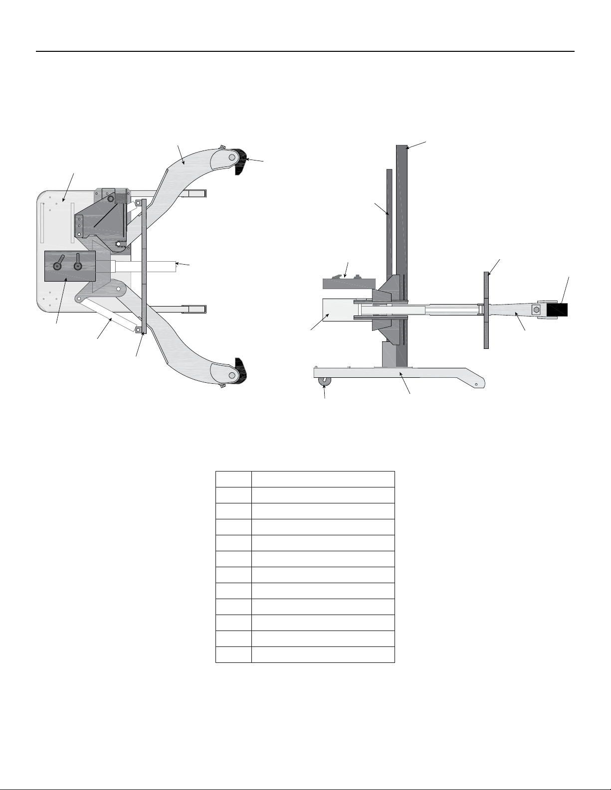
(Diagram shown for PTPH-102T, Some models have 3 Jaws)
ITEM DESCRIPTION
AJAW
BJAW TIP
C CAGE
DPUSHING ADAPTOR
E CAGE CYLINDER
F PUSHING CYLINDER
G CONTROL VALVES
H HOIST CYLINDER
I MAST
J BASE
K CASTERS
A
D
B
C
C
G
G
E
FA
B
I
H
J
K
J
Top view Side view
OVERVIEW
1. Major Components

7Form No. 1001292
Rev. 0 Dec. 21, 2022
© SPX FLOW, Inc.
2. Pushers
Included with the 100-TON pullers are THREE pushers and a coupler� String 2 pushers together to increase
the reach of the ram� Using a variety of combinations may be necessary to complete the pull of a deeply set
gear or bearing�
Included with the 200-TON puller are FOUR pushers� The diameters are 4 inches� The 200-TON does not include
coupler�
[229]
[483]
[89]
[89]
[102]
[19]
[10]
[19]
(89)PTHT-1162
(737)
(483)
(89)
PTHT-1163
(229)
(89)
(102)
(19)
(10)
(19)
PTHT-1164
Coupler
[89]
[89]
(203)
8.00
(102)
4.00
[102]
[89]
3.52 (89)
4 (102)
*Included with
200 TON only.
(102)
39.00
(991)
4
29.00
3.50
3.50
19.00
9.00
3.50
4.00
0.75
0.375
0.75
Note: Dimensions in Inches (mm)
Overview Continued
8Form No. 1001292
Rev. 0 Dec. 21, 2022
© SPX FLOW, Inc.
Overview Continued
PTHT-1180S
PTHT-1180A
PTHT-1180*
0.0
0.5
1.0
1.5
2.0
2.5
3.0
3.5
4.0
4.5
0.0
0.5
1.0
1.5
2.0
2.5
3.0
3.5
4.0
4.5
5.0
5.5
6.0
6.5
7.0
7.5
8.0
8.5
9.0
*Tip widths are 3 inches thick.
(0.0)
(12.7)
(25.4)
(38.1)
(50.8)
(63.5)
(76.2)
(88.9)
(101.6)
(114.3)
(127.0)
(139.7)
(152.4)
(165.1)
(177.8)
(190.5)
(203.2)
(215.9)
(228.6)
(0.0)
(12.7)
(25.4)
(38.1)
(50.8)
(63.5)
(76.2)
(88.9)
(101.6)
(114.3)
(mm) Inch
(mm)Inch
3. Jaw Tips
3 jaw tip sizes are available for 100 and 200 Ton puller models�
• PTHT-1180: standard with all models�
• PTHT-1180A: optional, for operations with limited space constraints�
• PTHT-1180S: optional, for operations with limited space constraints
ASSEMBLY
A� Ensure that shipping crate firmly rests on level ground in upright position.
B� Open small side panel and confirm that puller is resting firmly in upright position in the crate�
C� Remove remainder of plywood�
D� Inspect puller for any damage that may have been caused by shipping�
E� Save bolts that were used to brace the cart� These will be used for securing the included cart wheels to the
cart�
F� Inspect hoses for proper ratings� Connect the 10,000 psi hose to the port marked “10,000 psi only” on the
puller and the pressurized port on the pump� Connect hose with the lower pressure rating to the return port
on puller and pump�
G� Fill reservoir of pump with pump manufacturer specified oil� See pump or cylinder manual for details�
9Form No. 1001292
Rev. 0 Dec. 21, 2022
© SPX FLOW, Inc.
ADJUSTMENTS
1. Raising the Puller
A� Place cylinder control valve lever in “Hoist Oil Supply” position.
B� Raise puller by placing remote jog switch in “On” position and opening the puller hoist vertical control
valve�
C� Release remote jog switch� Close vertical control valve after reaching desired height�
2. Lowering the Puller
A� Place cylinder control valve lever in “Hoist Lower” position�
B� Lower puller by turning puller hoist vertical control valve counterclockwise�
C� Close vertical control valve after reaching desired height�
3. Hoist Travel Speed
NOTE: The restrictor valve, located at the top of the hoist cylinder, is used to control the rate of puller descent�
This valve should be set at the desired rate and locked in place using the nut on the valve shaft�
An appropriate starting point is one full turn from the closed position� This valve is a one-way restrictor only and
does not affect the rate at which the puller is raised�
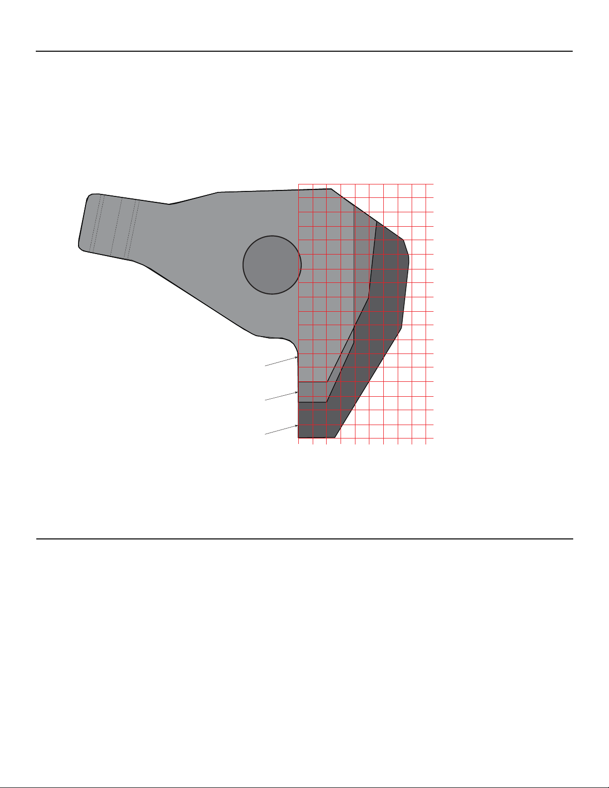
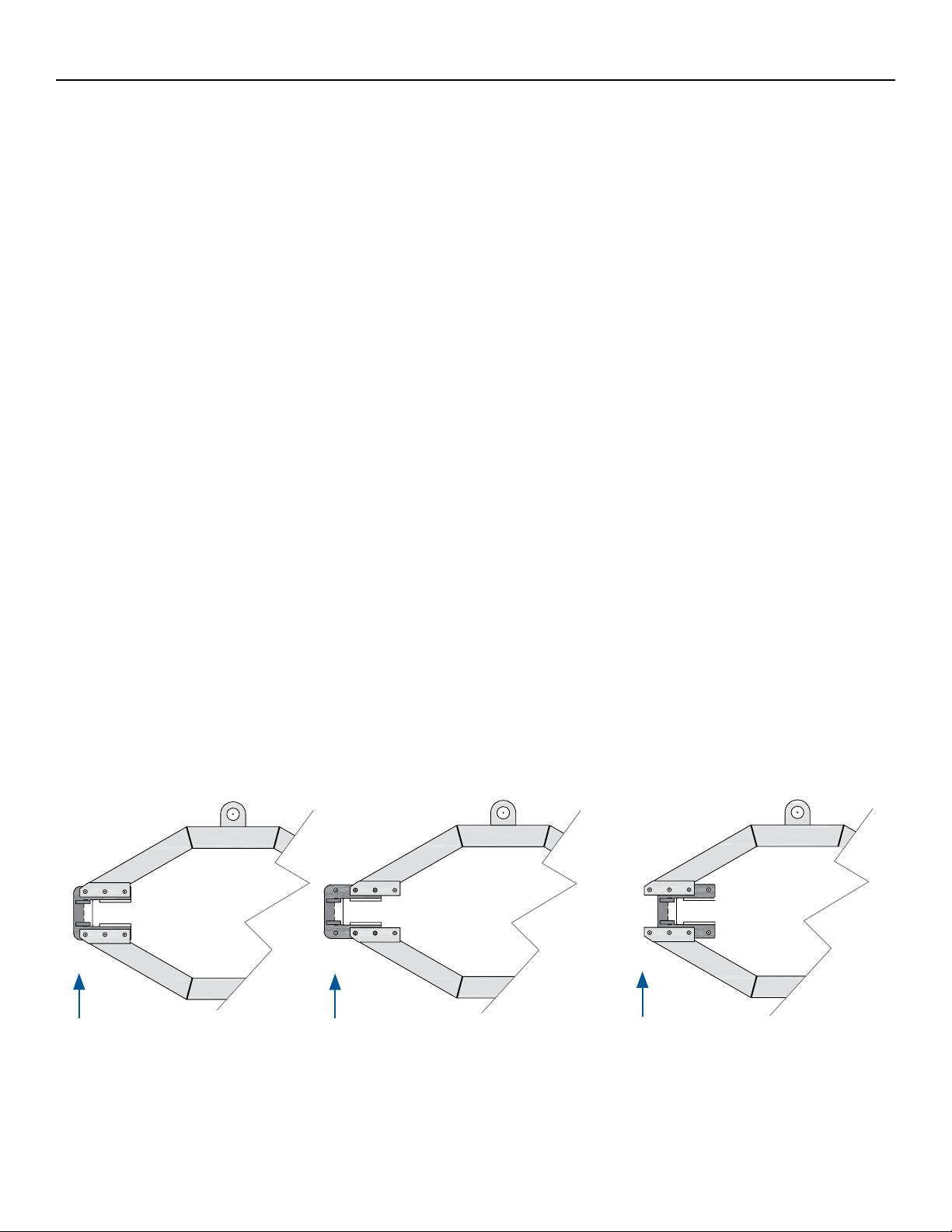
4. Changing the Jaw Spread
If opening/closing the jaws using the standard cage setting does not provide enough spread or does not
provide enough closure, use the following adjustments to achieve the maximum and minimum spreads�
A� Support the jaws�
B� Remove 6 cap screws, lock washers and nuts on 1 jaw guide at a time�
C� Slide jaw guide inward/outward on cage 1 bolt hole�
D� Replace 4 cap screws, lock washer, and nuts and tighten appropriately�
E� Reverse this process to return to standard jaw spread�
Jaw guide moved 1 bolt hole
OUT to increase spread.
Jaw guide moved 1 bolt hole
IN to decrease spread.
Default jaw guide position
when puller is shipped.
10 Form No. 1001292
Rev. 0 Dec. 21, 2022
© SPX FLOW, Inc.
Adjustments Continued
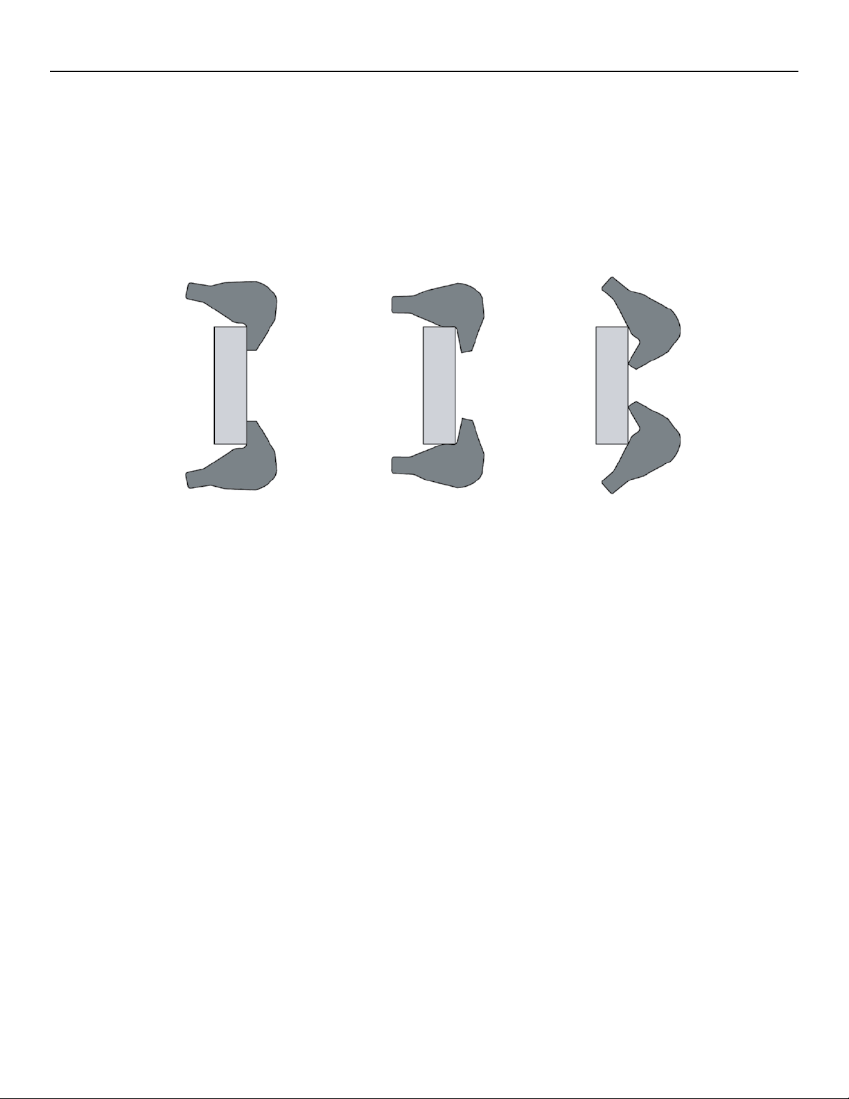
5. Adjusting Jaw Tips
A� Adjust jaw tips by turning 1-1/4” cap screw�
NOTE: Always use maximum pulling surface of jaw. To angle tip inward, turn cap screw clockwise.
To angle tip outward, turn cap screw counterclockwise. Before pulling, always make certain
machined caps are properly tted to curved surface.
IncorrectIncorrect
Correct Alignment
6. Adjusting Slide Rollers
A� Lower slide and puller assembly until it rests solidly on base�
B� Loosen 5/8” hex bolt�
C� Move roller using eye bolts on each side of roller�
D� Adjust roller until equal spacing is obtained between mast and slide tube on both roller side and
opposite side�
E� Tighten locking nut on eye bolt�
F� Tighten 5/8” hex bolt�

11 Form No. 1001292
Rev. 0 Dec. 21, 2022
© SPX FLOW, Inc.
Adjustments Continued
OPERATION
OPERATION IMPORTANT
: Hydraulic power is one of the safest methods for applying force
when used correctly. Be sure to read all instructions, warnings and cautions carefully.
Follow all safety precautions to avoid personal injury or property damage during system operation.
Power Team cannot be responsible for damage or injury resulting from unsafe use of product, lack
of maintenance or incorrect product and/or system operation.
It is important that the operator has a full understanding of all the instructions, warnings, cautions
and safety regulations before starting to operate equipment. When in doubt contact Power Team.
7. Removing Puller From The Cart
100-TON:
A� Support puller weight using lifting brackets provided�
B� Close puller hoist vertical control valve�
C� Disconnect puller hoist hose coupler at control panel�
D� Remove 2 of the 1/2” bolts which fasten locking plate to the puller lift bracket�
E� Remove puller from cart by rotating cart while keeping puller stationary�
200-TON:
A� Support puller weight using lifting brackets provided�
B� Close puller hoist vertical control valve�
C� Disconnect puller hoist hose coupler at control panel�
D� On each slide, remove the top and bottom 1/2” bolts� Do this on both the left and right slide, removing a
total of 4 bolts�
E� While keeping the puller supported and balanced, remove from the cart by moving the puller forward�
WARNING
MAINTENANCE
:
Always clean the puller after use and store in a clean, dry place.

12 Form No. 1001292
Rev. 0 Dec. 21, 2022
© SPX FLOW, Inc.
1. Setup
A� Transport the puller by use of the puller cart of forklift�
B� Line the puller up to the workpiece�
C� Open the jaws�
Opening The Jaws:
i� Place cylinder control valve lever in “Oil Supply” position�
ii� Place cage control lever in “Jaw Open” position and activate pump by pushing remote
switch to the “On” position to open jaws to the desired spread�
C� Position the workpiece to be removed in between the jaws�
D� Continue to adjust the height until the workpiece and extending cylinder are aligned� See RAISING THE
PULLER on page 9�
E� Close the jaws�
Closing The Jaws:
i� Place cylinder control valve lever in “Oil Supply” position�
ii� Place cage control lever in “Jaw Closed” position and activate pump by pushing
remote switch to the “On” position to close jaws to the desired spread or for clamping�
C� Adjust the jaw tips appropriately� See ADJUSTING JAW TIPS on page 10�
2. Pulling An Object:
A� Extend the cylinder ram towards the workpiece until there is contact�
Extending Cylinder:
i� Place cylinder control valve in “Extend” position�
ii� Activate pump with jog switch�
C� Continue to extend the ram� The workpiece will begin to move gradually off the shaft�
D� Retract the cylinder�
E� Completely remove the workpiece�
Retracting Cylinder:
i� Place cylinder control valve in the “Retract” position�
ii� Activate pump with jog switch�
NOTE: On a single acting cylinder the cylinder ram will retract without activating the pump.
Operation Continued

13 Form No. 1001292
Rev. 0 Dec. 21, 2022
© SPX FLOW, Inc.
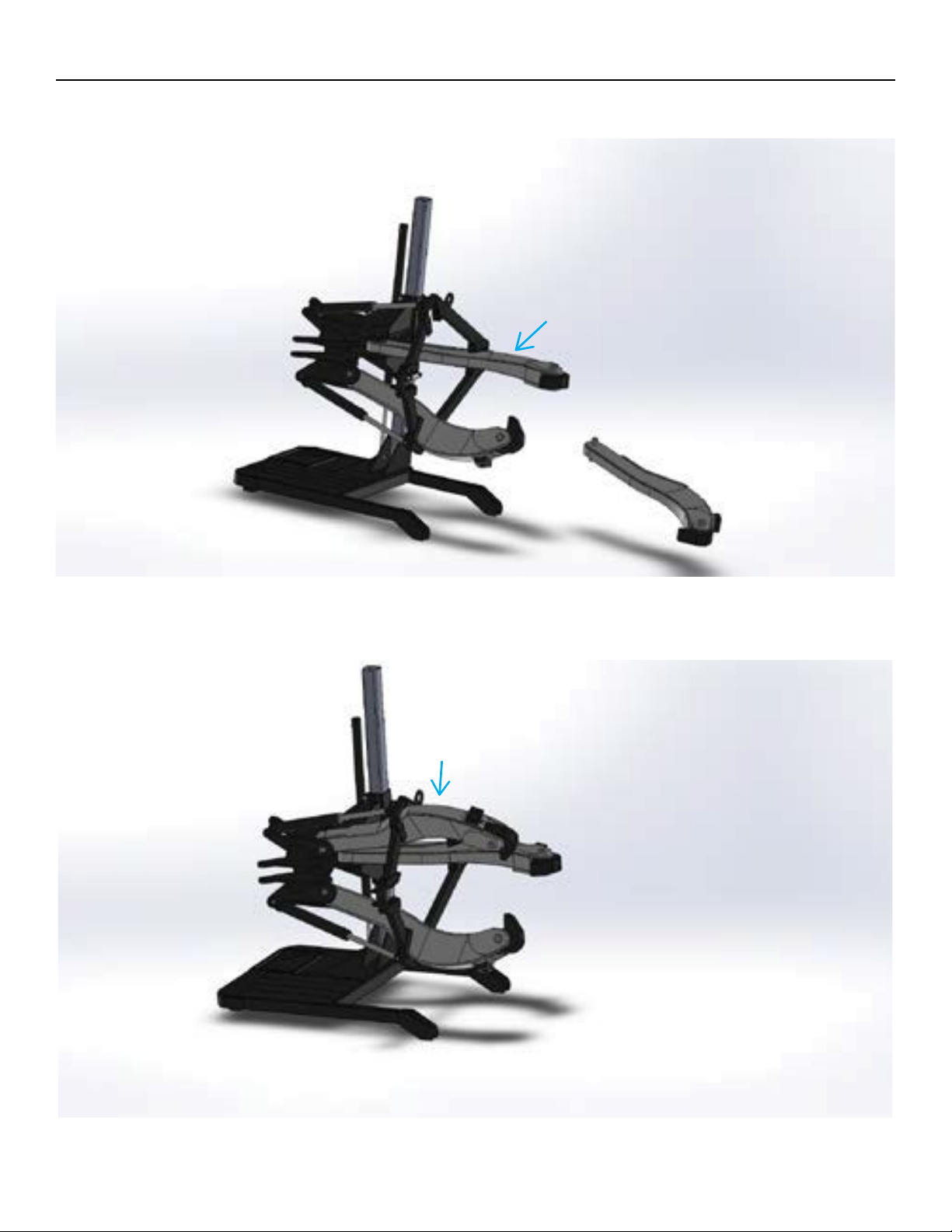
PTPH-123T TRANSFORMATION
A� Starting in a 2-jaw conguration, move the cage cylinder from the 2-jaw position to the 3-jaw position.
B� Remove the jaw on the left from the 2-jaw position�
14 Form No. 1001292
Rev. 0 Dec. 21, 2022
© SPX FLOW, Inc.
PTPH-123T Transformation Continued
C� Place the jaw into the lower 3-jaw position�
D� Place jaw from the left 2-jaw position into upper 3-jaw position to complete the transformation�
15 Form No. 1001292
Rev. 0 Dec. 21, 2022
© SPX FLOW, Inc.
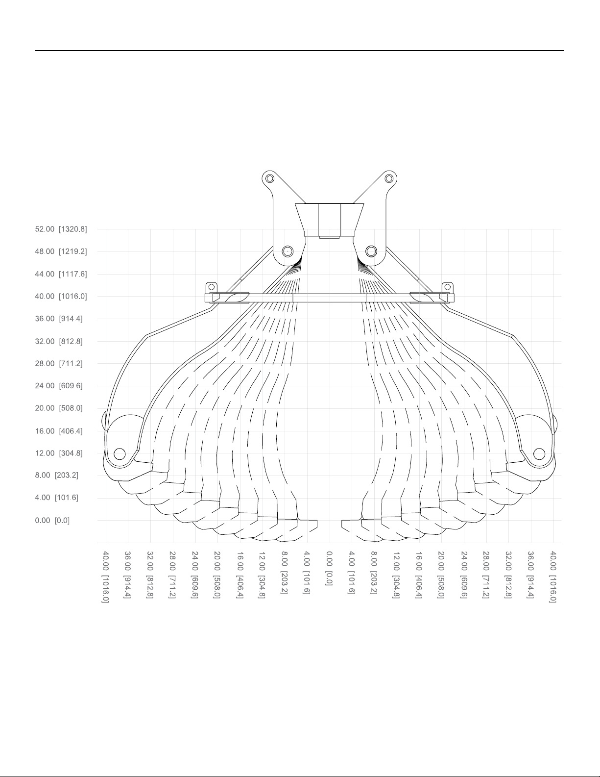
SPREAD RANGE
Use the diagram to determine the limitations of the jaw-opening� Spread ranges apply to all POWER TEAM
100-TON and 200-TON hydraulic puller systems. Gears, pulleys, wheels, sleeves, and other press t parts must t
within these limitations�
Spread Range Diagram
inch [mm]
inch [mm]

16 Form No. 1001292
Rev. 0 Dec. 21, 2022
© SPX FLOW, Inc.
POWER TEAM FACILITIES AND CONTACT
Rockford, Illinois USA
Customer Service/Order Entry
Tel: +1 800 541 1418
Fax: +1 800 288 7031
European Headquarters
Tel: +31 45 567 8877
Fax: +31 45 567 8878
Asia Pacific Headquarters
Tel: +65 6265 3343
Fax: +65 6265 6646
Technical Services
Tel: + 1 800 477 8326
Fax: + 1 800 765 8326
Shanghai, China
Tel: +86 21 2208 5888
Fax: +86 21 2208 5682

17 Form No. 1001292
Rev. 0 Dec. 21, 2022
© SPX FLOW, Inc.
English Original
SPX FLOW US LLC
5885 11th Street
Rockford, IL 61109-3699
United States of America
SPX FLOW Europe Ltd. -
Netherlands
SPX Hydraulic Technologies
Albert Thijsstraat 12
NL-6471 WX Eygelshoven
The Netherlands
EC DECLARATION OF CONFORMITY
We declare under our sole responsibility that our Hydraulic Puller Models:
*
PTPH-100T-E110, PTPH-100T-E220
PTPH-100TDA-E110, PTPH-100TDA-E220
PTPH-102T-E110, PTPH-102T-E220
PTPH-102TDA-E110, PTPH-102TDA-E220
PTPH-102TV-E110, PTPH-102TV-E220
PTPH-102DATV-E110, PTPH-102DATV-E220
PTPH-123T-E110, PTPH-123T-E220
PTPH-123TDA-E110, PTPH-123TDA-E220
PTPH-200T-E110, PTPH-200T-E220
to which this declaration relates are in conformity with the following:
EN, EN-ISO, ISO standards Title
Per the provisions of the Machinery Safety Directive 2006/42 EC
EN_ISO 12100 Safety of machinery, basic concepts, general principles for
design, risk assessment & risk reduction
EN 4413 Hydraulic Fluid Power –general rules and safety
requirements for systems & their components
Per the provisions of the EMC Directive 2014/30 EU
EN_61000-4-2 Electromagnetic Discharge Immunity test
EN_61000-4-3 Radiated, Radio Frequency, Electromagnetic Field
Immunity test
EN_61000-4-4 Electrical Fast Transient / Burst Immunity test
EN_61000-4-5 Surge immunity test
EN_61000-4-6 Immunity to Conducted Disturbances, Induced by Radio-
Frequency Fields
EN_61000-4-11 Voltage Dip and Interrupt test
EN 55011 Industrial, Scientific and Medical (ISM) Radio Frequency
Equipment-Electromagnetic Disturbance Characteristics-
Limits and Methods of Measurement
Per the provisions of the Low Voltage Directive 2014/35 EU
EN_60204-1 Safety of Machinery –Electrical equipment of machines –
Part 1 General requirements
Per the provisions of the RoHS Directive 2015/863 EU
Restriction of the use of certain hazardous substances in
electrical and electronic equipment
We hereby declare that the equipment specified under * conforms to the above quoted
European Community Directive(s) and Standard(s) as per the currently valid revision.
SPX Hydraulic Technologies is certified and registered to ISO 9001: 2015.
The Netherlands December 08th, 2022
------------------------------------------
Andreas J. Klemm, PhD

18 Form No. 1001292
Rev. 0 Dec. 21, 2022
© SPX FLOW, Inc.
English original
SPX FLOW US, LLC
5885 11th Street
Rockford, IL 61109-3699
United States of America
SPX FLOW Europe Ltd.
Ocean House, Wilmslow Road
Manchester, M20 2LY, UK
Andreas J. Klemm
SPX Flow Europe Ltd. –Netherl.
Albert Thijsstraat 12
NL-6471 WX Eygelshoven
UKCA DECLARATION OF CONFORMITY
We declare under our sole responsibility that our Hydraulic Puller Model:
*
PTPH-100T-E110, PTPH-100T-E220, PTPH-100TDA-E110,
PTPH-100TDA-E220, PTPH-102T-E110, PTPH-102T-E220
PTPH-102TDA-E110, PTPH-102TDA-E220, PTPH-102TV-E110,
PTPH-102TV-E220, PTPH-102DATV-E110, PTPH-102DATV-E220
PTPH-123T-E110, PTPH-123T-E220, PTPH-123TDA-E110,
PTPH-123TDA-E220
PTPH-200T-E110, PTPH-200T-E220
to which this declaration relates are in conformity with the following:
Legislation & standards Title
The Supply of Machinery (Safety) Regulations 2008 No. 1597 and amendments
EN_ISO 12100 Safety of machinery, basic concepts, general principles for
design, risk assessment & risk reduction
EN 4413 Hydraulic Fluid Power –general rules and safety requirements
for systems & their components
The Electromagnetic Compatibility Regulations 2016 No. 1091
EN_61000-4-2 Electromagnetic Discharge Immunity test
EN_61000-4-3 Radiated, Radio Frequency, Electromagnetic Field Immunity
test
EN_61000-4-4 Electrical Fast Transient / Burst Immunity test
EN_61000-4-5 Surge immunity test
EN_61000-4-6 Immunity to Conducted Disturbances, Induced by Radio-
Frequency Fields
EN_61000-4-11 Voltage Dip and Interrupt test
EN 55011 Industrial, Scientific and Medical (ISM) Radio Frequency
Equipment-Electromagnetic Disturbance Characteristics-
Limits and Methods of Measurement
The Electrical Equipment (Safety) Regulations 2016 No. 1101
EN_60204-1 Safety of Machinery –Electrical equipment of machines –
Part 1 General requirements
The Noise Emissions in the Environment by Equipment
for use Outdoors Regulation 2001 No. 1701
EN_3200L0014 Noise emission in the environment for use outdoors
ISO 3744 Sound Power Level Measurements
The Restriction of the Use of Certain Hazardous Substances in Electrical and
Electronic Equipment Regulations 2012 No. 3032
Restriction of the use of certain hazardous substances in
electrical and electronic equipment
We hereby declare that the equipment specified under * conforms to the above quoted
UK Legislation and international Standard(s) as per the currently valid revision.
SPX FLOW Europe Ltd. - Netherlands is certified and registered to ISO 9001: 2015.
The Netherlands December 15th, 2022
------------------------------------------
Andreas J. Klemm, PhD
This manual suits for next models
30
Table of contents
Other SPX FLOW Power Tools manuals

Popular Power Tools manuals by other brands

Baier
Baier BMF 501 Translation of the original instruction manual

Windsor
Windsor DOUBLE DRY DDH 86000000 operating instructions

Rongpeng
Rongpeng MCN90 operating instructions

Eastwood
Eastwood 13630 instruction manual

HAZET-WERK
HAZET-WERK 9035 VH operating instructions

MULTIQUIP
MULTIQUIP Mikasa MTX-80 Operation and parts manual


BGS technic
BGS technic 62506 instruction manual

Viega
Viega Picco 6 Instructions for use

Everwin
Everwin FCN90B Operation and maintenance manual

Parkside
Parkside PHLG 2000-2 Operation and safety notes
 Operating and maintenance instructions")
Clarke
Clarke CAT108 (1/2) Operating and maintenance instructions

Universal Tool
Universal Tool UT8726 operating instructions