SPX SPIDAR NIC-500s User manual

ii

Warranty Confirmation
iii
Warranty Confirmation
Return this card within 60 days of purchase to confirm your warranty. You can mail it to
Sensors & Software, fax it to +1-905-624-9365, or register your product online at
www.sensoft.ca/product-registration.
Name:
Company Name:
Address:
City:
State/Province:
Zip Code:
Country:
email:
Phone:
Fax:
Component Serial Numbers (refer to packing list or the sticker on the component)
Comp:
Serial #
Comp:
Serial #
Comp:
Serial #
Comp:
Serial #
Comp:
Serial #
Comp:
Serial #
Comp:
Serial #
Comp:
Serial #
Comp:
Serial #
Comp:
Serial #
Vendor Name:
Date Received:

Warranty Confirmation
iv

v
End User License Agreement
Please read the End User License Agreement at https://www.sensoft.ca/producteula/
Product Warranty and Limited Liability
Please refer to the terms and conditions included as part of your order acknowledgement and/or
invoice for full details of the product warranty and limited liability.
Important Safety Information
Read this manual in its entirety before attempting to operate the SPIDAR system. Note all safety
notices in the preface and throughout this manual
The battery charger/AC adapter must only be connected to a power outlet which provides a
protective earth (ground).
Connect the AC power cord only to designated power sources as marked on the battery
charger/AC adapter.
The battery charger/AC adapter is rated for indoors use only.
Do not replace detachable MAINS supply cords for the battery charger/AC adapter by
inadequately RATED cords.
The exterior of this product should be cleaned using a damp cloth.
Safety Symbols
Consult this documentation in all cases where this safety symbol appears. This
symbol is used to inform you of any potential HAZARD or actions that require your attention.
Do not attempt to open or dismantle any part of this equipment unless directed specifically by
this manual. Doing so may render the equipment faulty and may void the manufacturer’s
warranty.
Use authorized accessories only. Incompatible accessories may damage the equipment or give
inaccurate readings.
Follow your company and national safety procedures and or requirements when operating this
equipment in any environment or workplace. If you are unsure what policies or procedures
apply, contact your company or site’s occupational health and safety officer or your local
government for more information.

vi

vii
Table of Contents
1. Introduction.............................................................................................................1
2. Overview of NIC-500s............................................................................................3
2.1 NIC-500N 5
2.2 NIC-500P 6
2.3 NIC-500X 7
3. Getting Started.......................................................................................................9
3.1 Connecting all components –Single NIC-500 10
3.2 Connecting all components –multiple NIC-500s 13
3.3 GPS (optional) 14
3.4 Powering up 16
3.5 Connecting your device to the NIC-500 16
3.6 Powering down NIC-500 19
4. SPIDAR Software.................................................................................................21
4.1 Main screen 21
4.2 Project Management 22
4.3 System Configuration 26
4.4 Scope (NIC-500P and NIC-500X) 46
4.5 Line Scan 51
4.6 Admin 53
5. SPIDAR SDK........................................................................................................59
5.1 Activating SDK 59
5.2 Configuring the Ethernet connection 63
5.3 Changes in SDK mode 64
5.3.1 Changing the IP Address and Netmask 65
5.3.2 Data Collection with Pulse Trigger 66
5.4 Communication 67
5.4.1 Turning On/Off 68
5.4.2 Setting Parameters 68
5.4.3 Beginning and Ending Collection 68
5.4.4 Reading Data 69
5.5 Troubleshooting 69
6. Building a System.................................................................................................71
6.1 Couplers 72
6.2 NIC-500 Mounting 73
6.3 NIC-500 Stacking Hardware 73
6.4 Odometer Extension Cable 74
6.5 Power Requirements 75
7. Exported Data ......................................................................................................77
7.1 EKKO_Project 77
8. Compatibility.........................................................................................................79
8.1 Noggins 79
8.2 pulseEKKO 79
9. Technical Specifications.......................................................................................81

Table of Contents
viii
Appendix A: Data Collection Modes..............................................................................83
Appendix B: Components..............................................................................................85
Appendix C: Calculating GPS Latency..........................................................................87
Appendix D: GPR Knowledge.......................................................................................93
Appendix E: Port Specifications....................................................................................95
Appendix F: Health & Safety Certification .....................................................................97
Appendix G: GPR Emissions, Interference and Regulations.........................................99
Appendix H: Instrument Interference...........................................................................107
Appendix I: Safety around Explosive Devices.............................................................109
Appendix J: Wi-Fi Module ...........................................................................................111

Introduction
1
1. Introduction
Congratulations on your purchase of SPIDAR. The SPIDAR NIC-500s are a family of devices
used to connect multiple GPR systems and create a custom platform to address a wide range of
GPR applications. The variety of available configurations allow for a truly customizable multi-
channel system.
There are two ways to configure SPIDAR for multi-channel applications:
•Connect the same frequency GPR antennas to create an array system and collect a
wide swath of data in a single pass.
•Connect different frequency GPR antennas to create a multi-frequency system, and
collect data at varying depths in a single pass
Both systems increase the speed of data collection, resulting in increased productivity.
There are three variations of the NIC-500 available:
•NIC-500N –used to run Noggin systems. Each NIC-500N can run 2 Noggin sensors
simultaneously. Multiple NIC-500Ns can be connected together (daisy-chained) to run
several Noggins simultaneously.
•NIC-500P –used to run pulseEKKO PRO antennas. Each NIC-500P can run 2 pairs of
pulseEKKO PRO transmitters and receivers simultaneously. Multiple NIC-500Ps can be
connected together (daisy-chained) to run several pulseEKKO PRO antennas
simultaneously.
•NIC-500X –used to run pulseEKKO PRO antennas. Each NIC-500X can run any
combination of pulseEKKO PRO transmitters and receivers totaling up to 8
simultaneously.
A key feature of SPIDAR is that the data acquisition software and storage reside on the NIC-
500. As a result, any network capable device can be used to setup and control data acquisition
on a NIC-500. Once data has been collected, it can be downloaded to a computer, post-
processed and analyzed with the EKKO_Project software.
For those who would like to use GPR, but control it with their own data acquisition software,
SPIDAR can be put into SDK (Software Development Kit) mode. Details of SDK can be found
in Section 5.
This manual references NIC-500 firmware version V1 R5.

Introduction
2

Overview of NIC-500s
3
2. Overview of NIC-500s
This section explains the physical properties of the NIC-500s. Attributes common to all NIC-
500s are explained, followed by differences between NIC-500N, NIC-500P and NIC-500X.
Figure 2-1: SPIDAR NIC-500
A NIC (short for Network Interface Controller) is a device that allows users to collect data with
multiple GPR antennas simultaneously (Figure 2-1). Every NIC-500 contains:
•Wi-Fi –the NIC-500 broadcasts its own Wi-Fi signal. A user can connect their laptop or
tablet to this Wi-Fi network to control the NIC-500. Alternatively, a user can connect an
Ethernet cable directly from their device to the NIC-500 instead of connecting via Wi-Fi.
•SPIDAR software –the operational software that allows the user to setup parameters for
data acquisition. The user can access this through a web browser such as Google
Chrome on their device.
•Storage –a hard drive for data storage is built into the NIC-500.
•Voltage stabilizer –protects the system from spikes in the power supply and ensures an
even and steady distribution of power to the antennas and any accessories, such as a
GPS.
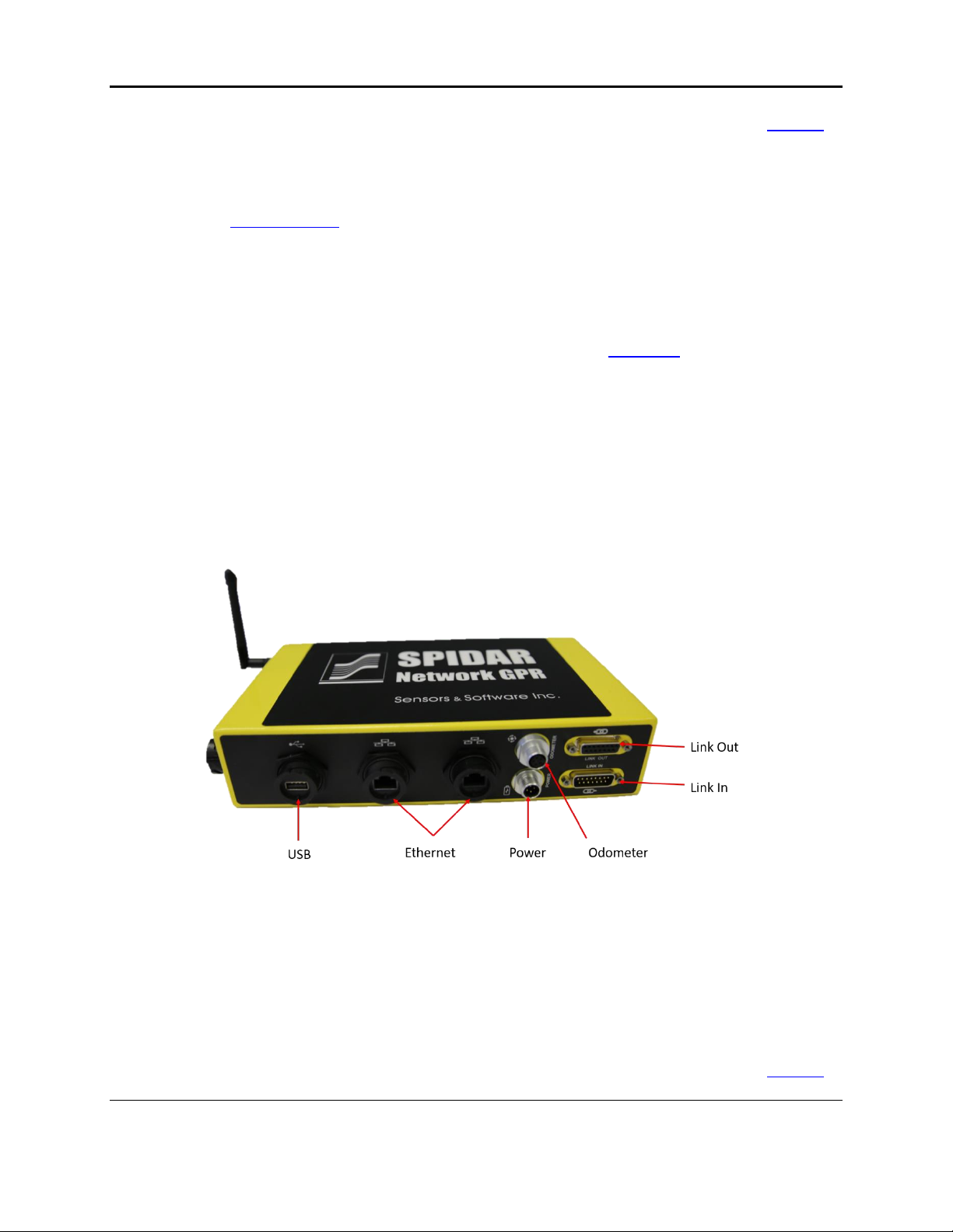
Each NIC-500 has several ports to connect antennas, power and accessories. Ports that are on
the long side (opposite side to where the antennas connect) are common to all NIC-500s
(Figure 2-2); these are described below. Ports unique to the NIC-500N, NIC-500P and NIC-
500X are described in the subsequent sections:
•USB –there are two USB ports (one on the long side, one on the front). A USB stick
can be inserted to download data off the machine. As well, the SPIDAR software can be
Overview of NIC-500s
4
updated by inserting a USB containing the upgrade file into one of these ports (Section
4.6.1)
•Ethernet–there are two Ethernet ports. If you are using a hardware connection to the
NIC-500, then you must run an Ethernet cable between your device and the NIC-500. If
you are daisy-chaining NIC-500s, you must plug an Ethernet cable from one NIC-500 to
the other.
•Power –this port could be used by customers who have a pulseEKKO PRO power
cable. However, it is recommended to power the system with the NIC-500 power cable
plugged into the Link In port (explained below).
•Odometer –if the data acquisition is to be triggered by an odometer, plug the odometer
cable into this port. An example of this is using a SmartCart platform to collect data.
•Link In –this port serves two purposes. For a single NIC-500 or the Master NIC-500 in a
daisy-chained setup, the power supply will be plugged into this port. If this is a
subordinate NIC-500, then the Sync cable will get plugged into this port coming from the
Master NIC link out cable.
•Link Out –if you are running a single NIC-500, this port will not be used. If you are
daisy-chaining two NIC-500s, then a NIC Sync cable will be plugged into the link out of
the Master NIC and connect into the Link In port of the subordinate NIC-500.
Figure 2-2: Connection ports common to all NIC-500s
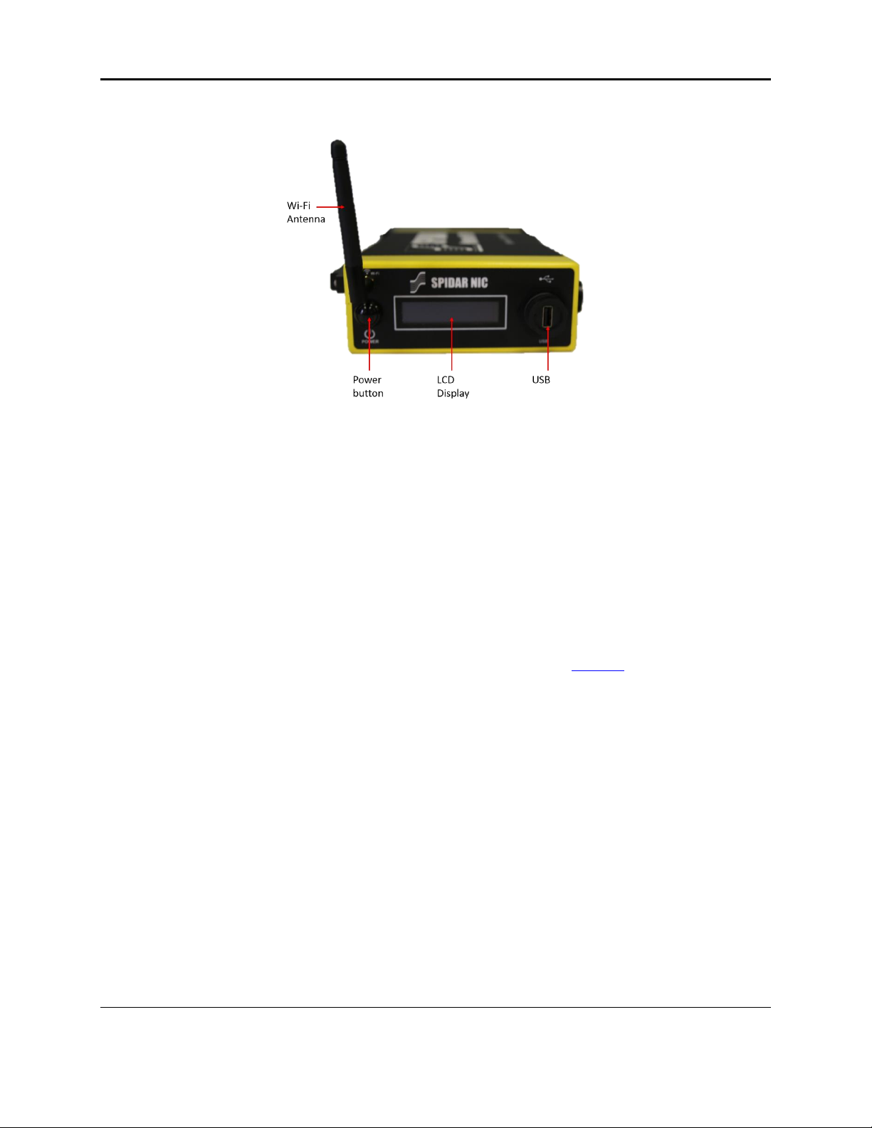
The features & ports on the front (short) side of the NIC-500 (Figure 2-3) are described below:
•Power button –Press the Power button to turn on the NIC-500.
•LCD Display –Displays the name of the network and the IP address
•USB –there are two USB ports (one on the long side, one on the front). A USB stick
can be inserted to download data off the machine. As well, the SPIDAR software can be
updated by inserting a USB containing the upgrade file into one of these ports (Section
4.6.1)
Overview of NIC-500s
5
Figure 2-3: Showing the front (short) side of the NIC-500
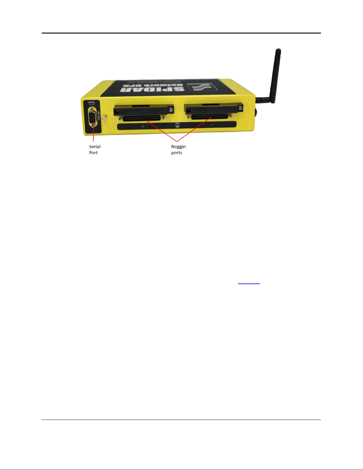
2.1 NIC-500N
A NIC-500N is a variation of the NIC that can be used to run up to 2 Noggins simultaneously.
Noggins are available in 4 center frequencies: 100, 250, 500 and 1000 MHz. Multiple NIC-
500Ns can be connected together, to run any number of Noggin systems; this is called daisy-
chaining.
On the long side of the NIC-500 (opposite side to the power and odometer connections), there
are two Noggin ports and a serial port (Figure 2-4), described below:
•Serial port –used to connect a GPS receiver. The GPS receiver can receive power from
this port, if power out is enabled. For more information, see Section 3.3.
•Noggin Ports –there are two numbered ports available to connect up to two Noggin
sensors. The NIC-500N can be run with only one Noggin, which would be a single
channel system.
Overview of NIC-500s
6
Figure 2-4: Long side of NIC-500N showing Noggin ports and serial port
2.2 NIC-500P
The NIC-500P can run up to 2 pairs of pulseEKKO PRO transmitters and receivers
simultaneously. pulseEKKO PRO antennas are available in 8 center frequencies: 12.5, 25, 50,
100, 200, 250, 500 and 1000 MHz. Multiple NIC-500Ps together can be connected to run any
number of pulseEKKO PRO antenna pairs; this is called daisy-chaining.
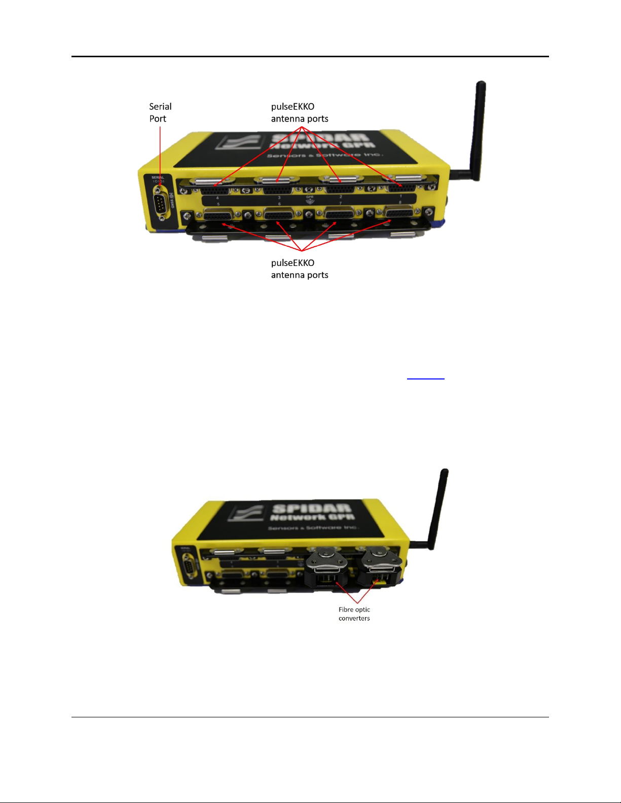
On the long side of the NIC-500 (opposite side to where the power and odometer connections
are), you will find 4 pulseEKKO ports and a serial port (Figure 2-5), which are described below:
•Serial port –used to connect a GPS receiver. The GPS receiver can receive power from
this port, if power out is enabled. For more information, see Section 3.3.
•pulseEKKO antenna ports –there are four numbered ports available to connect up to
two pulseEKKO transmitter and receiver pairs. If you are using low frequency antennas,
you will need to use fibre-optic converters to convert the fibre-optic cable to the 15-pin
antenna port input (Figure 2-6). The other end of these cables will run to the respective
transmitter or receiver. The NIC-500P can be run with a single transmitter/receiver pair
if desired, which would be a single channel system.

Overview of NIC-500s
7
Figure 2-5: Long side of NIC-500P showing pulseEKKO antenna ports and serial port
Figure 2-6: Fibre optic converters
2.3 NIC-500X
The NIC-500X allows for the connection of up to eight pulseEKKO PRO transmitters and
receivers simultaneously. The key distinction compared to the NIC-500P is that any
combination of transmitters and receivers can be connected to the NIC-500X. For example,
various configurations include 1 transmitter and 7 receivers, 1 transmitter and 5 receivers, and 4
transmitters and 4 receivers. Furthermore, the listening patterns of the transmitters and
receivers respectively can be controlled.
Overview of NIC-500s
8
Figure 2-7: Long side of NIC-500X showing pulseEKKO antenna ports and serial port
On the long side of the NIC-500X (opposite side of the power and odometer connections), there
are eight pulseEKKO ports and a serial port (Figure 2-7), described below:
•Serial port –used to connect a GPS receiver. The GPS receiver can receive power from
this port, if power out is enabled. For more information, see Section 3.3.
•pulseEKKO antenna ports –there are eight numbered ports available to connect up to
eight pulseEKKO PRO transmitters and receivers. If low frequency antennas are
employed, fibre-optic converters are required to convert the fibre-optic cable to the 15-
pin antenna port input (Figure 2-8). The other end of these cables will run to the
respective transmitter or receiver.
Figure 2-8: Fibre optic converters connected to the NIC-500.

Getting Started
9
3. Getting Started
This section explains how to connect all the components of the NIC-500 together. The first step
is identifying the required cables. Depending on the setup, the cables displayed in Figure 3-1
may not all be needed.
Figure 3-1: Common NIC cables
•NIC Sync Cable –required when connecting two NIC-500s together, regardless of the
type of NIC-500. It will plug into the Link Out port on the Master NIC-500 and into the
Link In port on the Subordinate NIC-500.
•NIC power cable –provides power to the NIC-500. One end plugs into the Link In port,
the other end plugs into the power supply.
•Ethernet Cable –required when connecting two NIC-500s together. The ends connect to
the Ethernet ports on the two NIC-500s. The cable pictured above has sealed ends, for
a more secure connection. However, if this is not available, a standard Ethernet cable
could be used.
Legacy pulseEKKO customers can also plug the pulseEKKO PRO power cable (Figure 3-2) into
the round power port on the NIC-500.
NOTE: If NIC-500s are daisy-chained, then the legacy power cable cannot be used.
The NIC power cable must be used in this instance, as it provides adequate current to
be drawn from the power supply.

Getting Started
10
Figure 3-2: pulseEKKO PRO power cable, not included with NIC-500s, but could be used to power a single NIC-500
3.1 Connecting all components –Single NIC-500
This section describes the cable connections to and from a NIC-500. Refer to Chapter 2 for
information on NIC-500 ports.
NOTE: Make sure all connections are made before plugging in the battery and powering
up the system.
Odometer: Determine if an odometer will be used to trigger the system (from a SmartCart for
example). If so, connect the odometer cable to the odometer port on the NIC-500 (Figure 3-3).
Ethernet: If a hardware connection (rather than Wi-Fi) is used to connect the device to the NIC-
500, connect an Ethernet cable between the computer/tablet and the Ethernet port on the NIC-
500 (Figure 3-3).
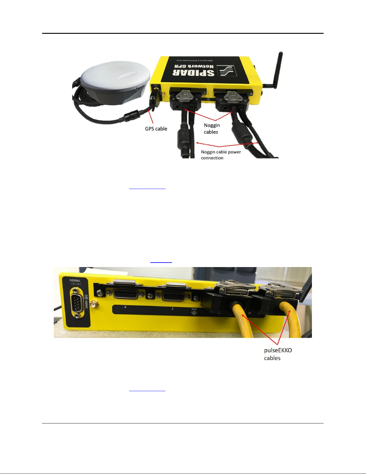
GPS: If a GPS is being used, the GPS must have a serial output cable. More information can
be found in Section 3.3. Connect this serial cable from the GPS to the serial port on the NIC-
500 (Figure 3-4).

Getting Started
11
Figure 3-3: Plugging in cables to a NIC-500
Figure 3-4: Connecting a GPS receiver to the serial port
The sections below explain the antenna cable connections for each type of NIC-500.
3.1.1 NIC-500N
Up to two Noggin systems can be plugged into the Noggin ports on a single NIC-500. The ports
are numbered ‘1’ and ‘2’. If you are running one Noggin, plug it into Port ‘1’ on the NIC-500.
Plug the 37-pin Noggin cable into the Noggin port, and the other end into the Noggin device
(Figure 3-5). See Section 8.1 on compatibility.
NOTE: Do not connect the Noggin cable power connection to a power supply in Figure
3-5
Getting Started
12
Figure 3-5: Connecting Noggin cables to the NIC-500N
Once completed, move on to Powering up in Section 3.4.
3.1.2 NIC-500P
Up to two pairs of pulseEKKO PRO antennas can be plugged into the pulseEKKO ports on the
NIC-500. These ports are numbered ‘1’, ‘2’, ‘3’ and ‘4’. Note that ports ‘1’ and ‘3’ should be
used for transmitters and ports ‘2’ and ‘4’ for receivers. In addition, ports ‘1’ and ‘2’ must be
used for a pair, before ports ‘3’ and ‘4’.
If you are connecting a single pair of antennas, the Tx will connect to port ‘1’ and the Rx will
connect to port ‘2’ (Figure 3-6). See Section 8.2 on compatibility.
Figure 3-6: Single pair of antennas connected to NIC-500P
Once completed, move on to Powering up in Section 3.4.
Table of contents


