SPX Hankison 600 Series User manual

600 Series
Electric Demand Drains
Models: EDD 601-04, EDD 602-04, EDD 603-04, EDD 604-04
FORM NO.: 7428306 REVISION: 09/2013 READ AND UNDERSTAND THIS MANUAL PRIOR TO OPERATING OR SERVICING THIS PRODUCT.
INSTRUCTION MANUAL

CONTENTS
GENERAL INFORMATION......................................... 1
1.0 FUNCTION .......................................................... 1
2.0 INSTALLATION .................................................... 2
3.0 MAINTENANCE................................................... 6
4.0 TROUBLESHOOTING GUIDE............................. 7
5.0 ENGINEERING DATA .......................................... 8
6.0 DIMENSIONS ...................................................... 8
7.0 COMPONENTS ................................................... 9
WARRANTY
1
GENERAL INFORMATION
1. Do not exceed max. operating pressure (see type plate).
NOTE: Maintenance work must only be carried out when
the device is not under pressure.
2. Only use pressure-proof installation material.
The feed line (1/2”) must be firmly fixed. Discharge line:
short pressure hose to pressure-proof pipe. Please
ensure that condensate cannot squirt onto persons or
objects.
3. In case conical connectors are used on the inlet side,
avoid excessive tightening of the connectors.
4. For locking or holding in position during installation, use
spanner area at inflow point.
5. The electrical installation must be carried out in compli-
ance with the valid regulations.
NOTE: Maintenance work is only allowed when the device is
in a de-energized condition. Electrical work must always be
performed by a qualified electrician.
6. Do not operate the device when there is a danger of
frost.
7. The Series 600 condensate drain will only function when
voltage is being applied to the device.
8. Do not use the test button for continuous draining.
9. Do not use the Series 600 condensate drain in hazardous
areas (with potentially explosive atmospheres).
10. Only employ original spare parts, otherwise the guaran-
tee will no longer be valid.
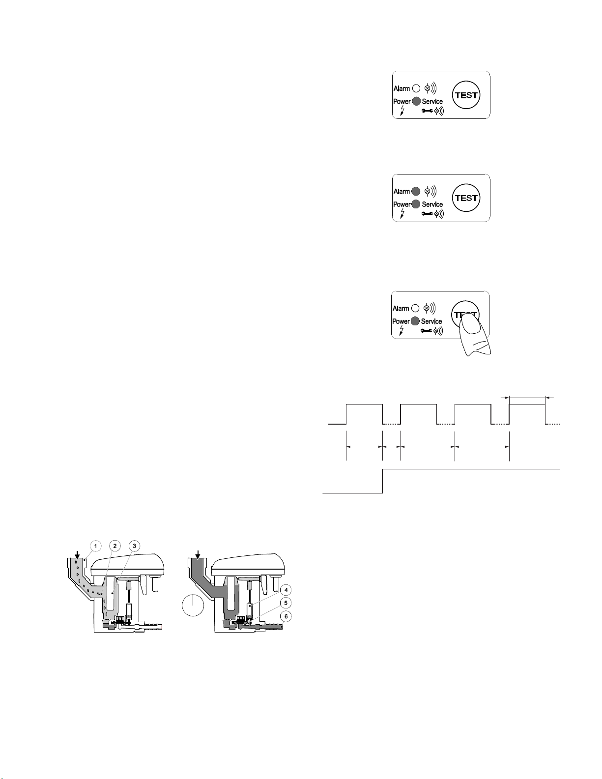
1.0 FUNCTION
The condensate flows through the feed line (1) into the
Series 600 condensate drain and accumulates in the hous-
ing (2). A capacitive sensor (3) continuously registers the
liquid level. As soon as the container is filled, a fixed waiting
period begins during which more condensate accumulates.
After the waiting time has expired the pilot valve (4) is then
activated and the diaphragm (5) opens the outlet line (6) for
discharging the condensate.
When the Series 600 condensate drain has been emptied,
the outlet line is closed again quickly and tightly without
wasting compressed air.
Ready for operation / Power on
The operating states of the Series 600 condensate drain are
indicated by two LEDs.
Malfunction / Alarm
If the condensate discharge is not functioning properly, an
alarm mode starts which is indicated by the flashing of the
red alarm LED.
Test function
1. Test of valve function and manual drainage: briefly press
button.
2. Test the alarm function (see below): press button for at
least one (1) minute.
Switching sequence of valve in alarm mode
Alarm signal via potential-free contact.
Alarm-mode function:
If normal conditions have not been restored after 1 minute,
a fault signal will be triggered:
• AlarmLEDashes.
• Alarmsignalswitchesover(canbetransmittedvia
potential-free contact).
• Valveopensevery80secondsforaperiodof60
seconds.
Once the fault is cleared, the Series 600 condensate drain will
automatically switch back to the normal mode of operation.
Malfunctioning could be caused by, e.g.:
• Mistakesduringinstallation
• Droppingbelowthenecessaryminimumpressure
• Excessivecondensatequantities(over-loading)
• Blocked/shutoffoutletline
• Extremeamountofdirtparticles
• Frozenpiping
60 s
60 s
80 s 80 s20 s

2
2.0 INSTALLATION
Only the displayed installation position of the Series 600 con-
densate drain valve is permissible. Never install in a horizon-
tal or any other tilted position.
• Feedpipe(1)andballvalve(2)atleast1/2‘’
• Nolterorscreeninfeedline
• Slopeinfeedline>1%
• Onlyuseballvalves(2)
• Operatingpressure:
Models 601 & 603 min. 18 psig max. 230 psig
Models 602 & 604 min. 12 psig max. 230 psig
• Shortpressurehose(4)xedonapressureresistantpipe
• Foreachmeterofrisingslopeintheoutletline(5),the
required minimum pressure will increase by 1.5 psig.
• Theriseoftheoutletline(5)mustnotexceed17feet
• Laycollectingline(7)3/4”with1%ofslope.
• Leaddischargepipe(6)fromthetopintocollecting
line (7).
• Priortothestart-up,alwayscarryoutaleaktestand
verify the correct engagement of the control unit.
Incorrect Installation Correct Installation
NOTE: Pressure Differences
Each condensate source must be drained separately.
Incorrect Installation Correct Installation
NOTE: Deflector Area
If drainage is to take place directly from a line, it is advis-
able to arrange the piping so that the air flow is diverted.
Incorrect Installation Correct Installation
NOTE: Continuous Slope
Water pockets must be avoided when laying feed line.
Incorrect Installations
NOTE:NoVentingLine
Do not install a vent line for a Series 600 condensate drain.
Installations, where a venting line is normally required, are
impossible in this case. Use another suitable drain valve.

3
2.1 Electrical Installation Notes before wiring:
1. The mains voltage must correspond to the permissible
voltage on the type plate.
2. For the supply voltage, a reliably accessible separator
must be provided close-by ( e.g. power plug or switch),
which separates all current-carrying conductors.
3. Atalow-voltagesupply(<50VAC/<75VDC),onlyusea
protectiveextra-low-lowvoltage(PELV).
4. Please ensure that the installation is carried out accord-
ing to the valid regulations.
5. Observe the terminal assignments.
6. DO NOT install when the device is energized.
7. Remove screws (1) and remove the upper part of the
cover (2).
8. Unscrew the threaded cable connection (3), remove
the plug (if there is one), and guide the cable (4) for the
power supply through.
9. Connect the cable (4) with terminals X1 (1.1, 1.2) (5).
10. Install the cables as shown (see also terminal assignment
in the following text).
11. Tighten the threaded cable connection (3) with a slightly
sealing effect.
12. Re-install the upper part of the cover (2) and tighten the
screws (1) finger tight.
Terminal assignment supply voltage (operating voltage)
X1 X2 X3
1212312
phase
neutral
normally open
common
normally closed
external test (IN1)
GND
1.1
1.2
2.1
2.2
2.3
3.1
3.2
• X1.1 Lmainsconnection
• X1.2 Nmainsconnection
L = Outer conductor
N = Neutral conductor
Terminal assignment low voltage (operating voltage)
X1 X2 X3
1212312
power
power
normally open
common
normally closed
external test (IN1)
GND
1.1
1.2
2.1
2.2
2.3
3.1
3.2
• X1.1 PowerSupply
• X1.2 PowerSupply

4
Connection of the potential-free contact and of the
external test:
1. Selection of the suitable cable.
2. Connect to X2 and X3 as shown.
3. Installation steps are the same as for the power supply
connection.
4. If the potential-free contact carries voltage that is dan-
gerous in the case of contact, a corresponding separator
must also be provided, as described above.
5. When using the potential-free contacts and the external
test connection, ensure sufficient clearance to the other
parts of the unit, or suitable insulation in accordance
with valid regulations.
6. When using a multiwire, common line for the connec-
tion of the potential-free contact and the external test,
this line must be suitable for the highest occurring volt-
age and the intended temperature range with regard
to its nominal ratings. (e.g. nominal range ≥300Vand
service temperature ≤1°C and ≥60°C.
Terminal assignment of the potential-free contact of
the external test
X1 X2 X3
1212312
power
power
normally open
common
normally closed
external test (IN1)
GND
1.1
1.2
2.1
2.2
2.3
3.1
3.2
Alarm / potential-free contact
• X2.1 N.O.
• X2.2 COM.
• X2.3 N.C.
N.C. - COM.
Contact closed during malfunction or power failure (fail-safe
principle).
N.O. - COM.
Contact closed during normal operation.
The contacts X 2.1 - 2.3 are potential free.
External test / remote control
• X3.1 externaltest(IN1)
• X3.2 GND
Contacts connected = test active = discharge
Contact open = test inactive
The contacts X 3.1 - 3.2 are NOT potential free.
NOTE:Foralow-voltagesupply(<50VAC/<75VDC),only
useaprotectiveextra-low-voltage(PELV).
Tighten the threaded cable connection with a slight sealing
effect.
2.2 Electrical Data
Supply voltage
(see type plate)
24...48VAC±10%(50...60Hz)/18...72VDC±10%
or
95...240VAC±10%(50...60Hz)/100...125VDC±10%
Power
consumption
P=0.6...3VA(W)
Recommended
cable-jack diameter
Ø 5.0... 10 mm (0.20"... 0.39")
Recommended
wire cross-section
Spring loaded
terminal
(voltage supply/
relay)
0.75...1.5 mm2(AWG 16...20)
Recommended
wire cross-section
Screw terminal
(voltage supply)
0.75...2.5 mm2(AWG 14...20)
Recommended
wire cross-section
Spring loaded
terminal
(external test)
0.75...1.0 mm2(AWG 18...20)
Recommended
wire cross-section
Screw terminal
(relay/external test)
0.75...1.5 mm2(AWG 16...20)
Connection data of
the potential free
contact
Switch to load *)
AC:max.250V/1A
DC: max. 30V/1A
Connection data of
the potential free
contact
Switch to low
signal *)
min.5VDC/10mA
Connection data
of the external test
contact
ontheunitside5VDC;switchingcurrent≥0.5 mA
Protection class IP 67
Overvoltage
category
II
VAC=Valternatingcurrent
VDC=Vdirectcurrent
*) The switching of loads means that the properties of the
contact are no longer suitable for the switching of low
signals.

5
2.3 Electrical Diagram
Pos: 52 /Beko Techni s che Doku mentati on/Inst allation/BEKOMAT/E-Sch ema @ 0 \ mod_1233758178163_2901.docx @ 13497 @ 1 @ 1
Electric diagram

6
3.0 MAINTENANCE
Beforemaintenanceworkalwaysensurethatthedeviceis:
• pressurelessand
• de-energized
Maintenance recommendation:
1. After 8,760 operating hours or one million switching
cycles, a maintenance message is released.
The green power LED flashes. Afterwards, or at the lat-
est after one year (8,760 operating hours), replace the
service unit (5) .
2. Prior to replacement of the service unit, a reset needs to
be carried out. The control unit is released by actuating
the arresting hook. When removed, the TEST button
below the LED must be pressed for at least five seconds.
3. Remove the control unit (1) by pressing the arresting
hook (2).
4. Unfasten from the outlet (3).
5. Remove the design shell (4) (if there is one) using a
screwdriver (10).
6. Detach the service unit (5) from the tubing at the inlet
by removing the union nut,
OR
remove the screws (6) from the angle nozzle (7).
OR
remove the screws (8) at the intermediate adapter (9)
and remove the latter from the service unit by pulling it
downwards.
7. Check whether or not the new service unit (5) goes with
the control unit (1).
8. Reassemble new service unit (5) in reverse order. Do not
over tighten screws (8).
Installation of the control unit on the service unit:
1. Check whether or not the service unit (5) goes with the
control unit (1).
2. Check whether or not the sealing mat (11) and the con-
tact springs (13) are clean, dry, and free from impurities.
3. Introduce the sensor (12) into the sensor tube plate (14).
4. Hangthehook(15)ofthecontrolunit(1)inthesensor
tube plate (14).
5. Press the control unit (1) against the service unit (5) and
snap into place.
Start-up subsequent to maintenance measures:
Always perform prior to the start-up:
1. Leak test of the screwed connector.
2. Check of the electrical connections.
3. Check of the correct engagement of the control unit.

7
4.0 TROUBLESHOOTING GUIDE
Symptom Possible Causes Corrective Action
No LED lights up Power supply faulty
Power supply board defective
Check voltage on the ID plate
Check wiring (external and internal)
Check plug connections
Check the circuit boards for possible dam-
age
All LEDs are continuously on Failure during the start of the program-
ming
Circuit board defective
Separate the device from the supply volt-
age. Restart after 5 seconds.
Check the circuit boards for possible dam-
age
Test button pressed, but no
condensate discharge
Feed and/or outlet line shut off or blocked
Worn parts (seals, valve core, diaphragm)
Control printed circuit board defective
Service unit defective
Minimum pressure not reached
Maximum pressure exceeded
Check feed line and outlet line
Replace worn parts
Check if valve opens audibly (press test
button several times)
Check printed circuit boards for possible
damage
Check operating pressure
Condensate discharge only
when the test button is
pressed
Feedlinewithinsufcientslope;cross-
section too small
Excessive condensate quantities
Service unit extremely dirty
Lay feed line with adequate slope
Replace the service unit
Device keeps blowing off air Service unit defective or dirty Replace the service unit

8
5.0 ENGINEERING DATA
6.0 DIMENSIONS
2.87 (73)
6.48 (164.7)
7.05 (179)
4 - 8 Nm
4.63 (117.6)
3.49 (88.6)
INLET
5.12 (130)
OUTLET
inch (mm)
ALARM
SIGNAL
ELECTRICAL
CONNECTION
INLET
Models 601 & 603 Models 602 & 604
Min. / Max. Operating Pressure
(see type plate) 18 PSI / 230 psi 12 PSI / 230 psi
Min. / Max. Air Temperature
(see type plate) +34°F / +158°F +34°F / +140°F
Condensate Inflow 1/2" NPT 1/2"BSP
Condensate Outflow 1/4"NPTwith3/8"BarbedHoseConnector
Weight (empty) 2.2 lbs.

9
1. Screw 3.5 x 10
2. Upper part of cover
3. Cord packing 2 x 352
4. Circuit board
5. Sensor
6. Lower part of the cover
7. Cable bushing
8. Sealing mat
9. Service unit
10. Hose connector Ø 1/4
11. O-ring 20 x 2
12. Intermediate adapter
13. Screw M6 x 12
14. O-ring 14 x 1.78
15. Angle adaptor G 1/2
16. Design shell (N/A: Models 603 & 604)
7.0 COMPONENTS


AUTHORIZATION FROM THE SERVICE DEPARTMENT IS NECESSARY BEFORE MATERIAL
IS RETURNED TO THE FACTORY OR IN-WARRANTY REPAIRS ARE MADE.
WARRANTY
The manufacturer warrants the product manufactured by it, when properly installed, operated, applied, and maintained in accor-
dancewithproceduresandrecommendationsoutlinedinmanufacturer’sinstructionmanuals,tobefreefromdefectsinmaterialor
workmanshipforaperiodofone(1)yearfromthedateofshipmenttothebuyerbythemanufacturerormanufacturer’sauthorized
distributor, or eighteen months from the date of shipment from the factory, whichever occurs first, provided such defect is discovered
andbroughttothemanufacturer’sattentionwithintheaforesaidwarrantyperiod.Themanufacturerwillrepairorreplaceanyproduct
or part determined to be defective by the manufacturer within the warranty period, provided such defect occurred in normal service
and not as a result of misuse, abuse, neglect or accident.
The warranty covers parts and labor for the warranty period. Repair or replacement shall be made at the factory or the installation
site, at the sole option of the manufacturer. Any service performed on the product by anyone other than the manufacturer must first
be authorized by the manufacturer. Normal maintenance items requiring routine replacement are not warranted. Unauthorized service
voids the warranty and any resulting charge or subsequent claim will not be paid. Products repaired or replaced under warranty shall be
warranted for the unexpired portion of the warranty applying to the original product. The foregoing is the exclusive remedy of any buyer
ofthemanufacturer’sproduct.Themaximumdamagesliabilityofthemanufactureristheoriginalpurchasepriceoftheproductorpart.
THEFOREGOINGWARRANTYISEXCLUSIVEANDINLIEUOFALLOTHERWARRANTIES,WHETHERWRITTEN,ORAL,ORSTATUTORY, AND IS
EXPRESSED IN LIEU OF THE IMPLIED WARRANTY OF MERCHANTABILITY AND THE IMPLIED WARRANTY OF FITNESS FOR A PARTICULAR
PURPOSE.THEMANUFACTURERSHALLNOTBELIABLEFORLOSSORDAMAGEBYREASONOFSTRICTLIABILITYINTORTORITSNEGLIGENCEIN
WHATEVERMANNERINCLUDINGDESIGN,MANUFACTUREORINSPECTIONOFTHEEQUIPMENTORITSFAILURETODISCOVER,REPORT,REPAIR,
ORMODIFYLATENTDEFECTSINHERENTTHEREIN.THEMANUFACTURER,HISREPRESENTATIVEORDISTRIBUTORSHALLNOTBELIABLEFORLOSS
OFUSEOFTHEPRODUCTOROTHERINCIDENTALORCONSEQUENTIALCOSTS,EXPENSES,ORDAMAGESINCURREDBYTHEBUYER,WHETHER
ARISINGFROMBREACHOFWARRANTY,NEGLIGENCEORSTRICTLIABILITYINTORT.
The manufacturer does not warrant any product, part, material, component, or accessory manufactured by others
andsoldorsuppliedinconnectionwiththesaleofmanufacturer’sproducts.
SERVICE DEPARTMENT: (724) 746-1100

SPX
1000 Philadelphia Street
Canonsburg, PA 15317-1700 U.S.A.
P: (724) 745-1555
F: (724) 745-6040
www.hankisonintl.com
Improvements and research are continuous at SPX.
Specifications may change without notice.
ISSUED 09/2013 Form No.: 7428306 Revision: None
COPYRIGHT ©2013 SPX Corporation
600 Series
Electric Demand Drains
Models: EDD 601-04, EDD 602-04,
EDD 603-04, EDD 604-04
This manual suits for next models
4
Table of contents
Other SPX Heat Pump manuals

Popular Heat Pump manuals by other brands


NIBE-BIAWAR
NIBE-BIAWAR HK 200M installation manual

Riello
Riello AARIA START Installation and technical service instructions

Kronoterm
Kronoterm WPLV-09-S1 NT installation manual

Daikin
Daikin Altherma 3 R F EHFH03S18DJ3V Operation manual

Zodiac
Zodiac POWER FORCE Series Instructions for installation and use

Sanyo
Sanyo THS2432 Submittal sheet