SR Research EyeLink 1000 User manual
EyeLink1000 Installation Guide
Tower, Desktop, LCD Arm, Primate,
and Long Range Mounts
Remote, 2000 Hz and Fiber Optic
Camera Upgrades
Version 1.5.2
Copyright 2005-2010, SR Research Ltd.
EyeLink is a registered trademark of SR Research Ltd.,
Mississauga, Ontario, Canada

ii
2005
-
2010
SR Research Ltd.
Read instructions before use.
US
C
Certified
Entela Safety Mark: Compliance of this product
with UL 60950 3rd Edition, CSA C22.2 No
60950-00-CAN/CSA is certified by Entela, an
independent testing body.
CLASS 1 LED DEVICE
IEC 60825-1 (Ed. 1.2:2001)
CONTACT ADDRESS
SR Research Ltd.
150-A1 Terence Matthews Crescent
Ottawa, Ontario, Canada K2M 1X4
Fax: 613-482-4866
Phone: 613-271-8686
Toll Free: 1-866-821-0731
Email: sup[email protected]om
Sales: http://www.sr-research.com/
Support: http://www.sr-support.com/

2005
-
2010 SR Research Ltd.
iii
Table of Contents
1. Introduction..................................................................................................... 1
1.1 Suggested Equipment Layout ............................................................2
2. Installation and System Cabling ................................................................. 4
2.1 Unpacking ........................................................................................4
2.2 Display PC Hardware Installation ......................................................4
2.3 Setting up the Host PC ......................................................................5
2.3.1 Rebuilding the Host PC ............................................................................. 5
2.4 Host PC Wiring .................................................................................6
2.4.1 Standard Camera System Installation .................................................... 7
2.4.2 Fiber Optic Camera System Installation................................................ 10
2.4.3 The Fiber Optic Camera Adapter............................................................ 12
2.4.4 EyeLink Response Device Installation ................................................... 13
2.4.5 Analog Card Installation ......................................................................... 14
2.4.6 Camera Lens Selection............................................................................ 15
3. Tower Mount Installation ........................................................................... 16
3.1 Mounting the Tower to a Table.........................................................17
3.2 Mounting the High-speed Camera and Cabling.................................18
3.2.1 Cabling for the Standard Camera .......................................................... 19
3.2.2 Cabling for the Fiber Optic Camera........................................................ 19
3.3 Adjusting Head Rest Components....................................................20
4. Desktop Mount / EyeLink Remote Installation..................................... 21
4.1 Mounting the EyeLink 1000 High-Speed Camera and Cabling...........21
4.1.1 Cabling for the Standard Camera .......................................................... 23
4.1.2 Cabling for the Fiber Optic Camera........................................................ 23
4.2 Adjusting the Desktop Mount (Monocular, Binocular and Remote Recording)
24
4.3 EyeLink Remote Hardware Adjustment for the Desktop Mount .........25
5. LCD Arm Mount Installation ...................................................................... 26
5.1 Choosing a Table.............................................................................26
5.2 Affixing the Arm Base to a Tabletop .................................................28
5.3 Assembling the LCD Arm Components.............................................29
5.4 Mounting the EyeLink 1000 High-Speed Camera..............................30
5.5 Attaching the Cables .......................................................................31

iv
2005-2009 SR Research Ltd.
5.6 Adjusting the Tension Points on the LCD Arm ..................................33
5.7 LCD Arm Mount Adjustments for Monocular and Remote Recording .33
5.8 Disassembling and Transporting the LCD Arm Mount ......................34
5.8.1 Option 1: Remove LCD Arm and Camera Assembly as a Unit ............ 35
5.8.2 Option 2: Remove Camera Assembly then Remove the LCD Arm ....... 35
6. Primate Mount Installation ........................................................................ 36
6.1 Primate Mount Hardware Considerations.........................................37
7. Long Range Mount Installation ................................................................. 40
7.1 Description of the Components........................................................40
7.2 Overview of Setting the Mount .........................................................41
7.3 Securing the EyeLink 1000 Fiber Optic Camera Head.......................42
7.4 Securing the Illuminator..................................................................43
7.5 Affixing the Mounting Bar................................................................44
7.6 Cabling for Long Range System........................................................44
7.7 Long Range Camera Setup ..............................................................46
7.7.1 Acquire Preliminary Measurements ....................................................... 46
7.7.2 Assemble the Long Range Mount Components ..................................... 46
7.7.3 Align the Camera Head and Illuminator................................................ 48
7.7.4 Put the Mount into Position and Find the Eye ....................................... 49
7.8 Installation in a MEG Room.............................................................50
7.9 MRI Installation ..............................................................................52
7.9.1 Determine the Mount and Configuration to Use .................................... 53
7.9.2 Mounting the Camera Head and Illuminator......................................... 57
7.9.3 The Head Coil Mirror ............................................................................... 59
7.9.4 Measuring and Using the Eye-to-Camera Distance .............................. 60
7.9.5 Align the Camera Head and Illuminator................................................ 60
7.9.6 Put a Volunteer/Confederate in the Scanner and Find the Eye(s) ...... 60
7.9.7 Adjust Image Thresholds and Focus the Lens ...................................... 61
7.10 Calibration and Drift Correcting with the Long Range System ...........62
7.10.1 Calibrating Atypical Spatial Areas ..................................................... 62
7.10.2 Drift Correction..................................................................................... 63
8. Testing the Host PC Installation............................................................... 65
8.1 Running the EyeLink Host Program .................................................65
8.2 Troubleshooting Instructions...........................................................67

2005
-
2010 SR Research Ltd.
v
8.2.1 SCD file does not exist ............................................................................ 67
8.2.2 “No Hardware” error ............................................................................... 67
8.2.3 EyeLink CL camera not found ................................................................ 67
8.2.4 ERROR: no sync found............................................................................ 67
8.2.5 Error: No Optilink head found. ............................................................... 68
8.3 EyeLink Data Storage......................................................................68
8.4 Customizing Your PHYSICAL.INI Settings.........................................68
8.4.1 Measuring screen_phys_coords ............................................................. 69
8.4.2 Measuring screen_distance .................................................................... 70
8.4.3 Entering Values into PHYSICAL.INI ....................................................... 70
9. Display PC Software Installation............................................................... 72
9.1 Windows Installation.......................................................................72
9.1.1 Installing the EyeLink 1000 Experiment Programming Kit .................. 72
9.1.2 Installing the IO Port Access Driver........................................................ 72
9.1.3 Installing the EyeLink Data Viewer and Experiment Builder Software73
9.1.4 USB License Key Installation ................................................................. 73
9.1.5 Setting up EyeLink 1000 Network Connection...................................... 73
9.1.6 System and Programming Tools Required............................................. 74
9.2 Mac OSX Installation ......................................................................75
10. Appendix A: Host PC Hardware Installation ........................................... 76
10.1 Installing the High-Speed Frame Grabber - PCI card.........................76
10.2 Installing the Ethernet Card ............................................................76
10.3 Installing the Data Translation Analog Card (Optional) .....................77
11. Appendix B: Windows 2000/XP Host PC Software Installation ......... 78
11.1 Install System Commander..............................................................78
11.2 Resize Existing Disk Partition ..........................................................79
11.3 Create the EyeLink 1000 Host Application partition .........................81
11.4 Copy the Host Application files to the New Partition..........................82
11.5 Configuring the Keyboard................................................................83
11.6 Transfer the System to make the EyeLink Partition Bootable ............83
11.7 Organize System Commander’s ‘OS Selection Menu’.........................84
11.8 Automated boot into the EyeLink 1000 Operating System.................85
12. Appendix C: Host PC Software Installation Under Windows Vista .... 86
12.1 Formatting the Hard Drive under ROM-DOS ....................................86

vi
2005-2009 SR Research Ltd.
Figures
Figure 1-1: Suggested EyeLink 1000 System Layout ..................................................... 2
Figure 2-1: The Standard Camera (left) and Fiber Optic Camera Base Box and Camera
Head (right).................................................................................................................... 6
Figure 2-2: Host and Display PC Basic Cabling.............................................................. 8
Figure 2-3: Fiber Optic Camera Components................................................................ 10
Figure 2-4: Camera Base Box and Cabling affixed to the side of the Host PC .......... 12
Figure 2-5: The Camera Adapter (left) with Camera Head inserted (right) ................ 13
Figure 2-6: VPixx Button Boxes (left), VPixx Button Box Parallel Port Pin Adapter,
modified Gravis Destroyer gamepad, and Microsoft USB Sidewinder gamepad
(right)............................................................................................................................ 13
Figure 3-1: Components of EyeLink 1000 Tower .......................................................... 16
Figure 3-2: Clamping Chinrest to Table (right), Placing and Adjusting Tower Mount17
Figure 3-3: Adjust Height of Tower to Half the Screen Area of Monitor ..................... 18
Figure 3-4: Views of the EyeLink 1000 Tower and Camera ......................................... 18
Figure 3-5: Camera and Illuminator Cables for a Standard Camera Used in the Tower
Mount........................................................................................................................... 19
Figure 3-6: Fiber Optic Camera in the Tower Mount.................................................... 20
Figure 4-1: EyeLink 1000 Desktop Mount Components.............................................. 21
Figure 4-2: Desktop Mount Camera Adjustment .......................................................... 21
Figure 4-3: Camera Level Position for Remote and Stabilized Monocular Recording22
Figure 4-4: Camera Angled Position for Stabilized Binocular and Monocular Recording
...................................................................................................................................... 23
Figure 4-5: Camera and Illuminator Cables from Desktop Mount ............................. 23
Figure 4-6: Fiber Optic Camera in the Desktop Mount viewed from the front (left) and
rear (right).................................................................................................................... 24
Figure 5-1: Typical EyeLink 1000 LCD Arm Mount Installation................................. 26
Figure 5-2: EyeLink 1000 LCD Arm Mount Components: LCD Arm Mount Base, Arm,
Camera and LCD Assembly....................................................................................... 27
Figure 5-3: Two Configurations of the LCD Arm Mount Base ..................................... 28
Figure 5-4: Rearview of the LCD Arm Mount’s Camera (top) and LCD Monitor (bottom)
...................................................................................................................................... 31
Figure 5-5: Cables Emerging from the Bottom of the LCD Arm.................................. 32
Figure 5-6: Securing the LCD Arm for Disassembling and Transporting .................. 34
Figure 6-1: Typical EyeLink 1000 Primate Mount Installation ................................... 36

2005
-
2010 SR Research Ltd.
vii
Figure 7-1: EyeLink 1000 Long Range Mount affixed to a Desktop Base (left) and
pictured with a variety of lenses and Tripod Adapter (right) ................................. 40
Figure 7-2: Mounting Bar and Clips-note Guide Pins on the Camera Head clip (left)40
Figure 7-3: Fiber Optic Camera Head with lens (left), attached to the Camera Head
Bracket (center), Guide Holes in the Camera Head Bracket accept Guide Pins from
Camera Head Clip (right) ........................................................................................... 42
Figure 7-4: Bracket in the Level Position (left) and Angled (right) – without the Camera
Head (top) and with the Camera Head (bottom)...................................................... 43
Figure 7-5: Illuminator attached using two brass thumbscrews (left), or single
thumbscrew (center), rotates around the Mounting Bar when its knob is released
to adjust tilt (right) ..................................................................................................... 43
Figure 7-6: Tripod Adapter (left), Desktop Base (middle) and Mounting Bar attached to
the Tripod Adapter using Two Brass Bolts (right)................................................... 44
Figure 7-7: Male DB-9 connector (left-to-right), gender changer with female connector
showing, BNC connectors, LEMO connectors, and Battery System..................... 45
Figure 7-8: Focusing the Illuminator.............................................................................. 47
Figure 7-9: Pointing the Camera – a visible illumination boundary indicating poor
lighting of the left portion of the camera’s view (left) and a fully illuminated target
indicating intense and uniform illumination (right) ............................................... 49
Figure 7-10: Screen Mount used in conjunction with the Elekta Neuromag screen (left)
and a custom-built wood-frame screen (right) ........................................................ 52
Figure 7-11: Tray Mount with optional screen for Siemens family of scanners (left),
Screen Mount (middle), and Siemens Allegra short bore mount (right)............... 53
Figure 7-12: Tray Mount for Siemens family of scanners pictured from above with
optional screen (left), from behind with screen (top-middle) and configured for
user-supplied screen (bottom-middle), riser block on screen (top-right) and from
above (bottom-right) ................................................................................................... 55
Figure 8-1: Booting into the EyeLink Partition.............................................................. 65
Figure 8-2: Host Application Camera Setup Screen ..................................................... 66
Figure 8-3: Host PC Set Options Screen ........................................................................ 66
Figure 8-4: Measuring screen_phys_cords..................................................................... 69
Figure 10-1: High-Speed Frame Grabber....................................................................... 76
Figure 10-2: D-Link Ethernet Card ................................................................................ 77
Figure 10-3: Analog Card................................................................................................. 77
Figure 11-1: License Code Entry..................................................................................... 78
Figure 11-2: Enable System Commander ...................................................................... 79
Figure 11-3: Select Partitioning then Manual Partitioning .......................................... 79
Figure 11-4: Partition Selection and Resizing ............................................................... 80

viii
2005-2009 SR Research Ltd.
Figure 11-5: Partition and Partition Type Selection...................................................... 80
Figure 11-6: Create a Custom FAT 32 Partition............................................................ 81
Figure 11-7: Windows Explorer Tools Folder Options… Dialog .................................. 82
Figure 11-8: Select Partition to Rename ........................................................................ 84
Figure 11-9: Select Description and Icons ..................................................................... 85
Figure 11-10: Order Add and Remove ............................................................................ 85

Introduction
2005
-
2010 SR Research Ltd.
1
1. Introduction
This document provides hardware and software installation instructions for the EyeLink 1000
using the Tower, Desktop, Primate, LCD Arm or Long Range mounts.
There are two EyeLink 1000 cameras (the Standard camera and the Fiber Optic camera) and
each is compatible with all of the different mount types with the exception that only the Fiber
Optic camera works with the Long Range Mount. The cameras have identical technical
specifications, though the Fiber Optic camera has a non-ferromagnetic optimized design to
operate in electromagnetically sensitive environments such as is required for EEG, MEG or
MRI.
Both EyeLink 1000 cameras can be upgraded to enable 2000 Hz recording, or to use the
EyeLink 1000 as a Remote eye tracker that requires no head stabilization. While the 2000 Hz
camera upgrade is compatible with all mount options, the EyeLink Remote upgrade works with
only the Desktop and LCD Arm Mounts.
For the simplicity of presentation, these eye tracker configurations are collectively referred to as
the EyeLink 1000 throughout this document, with important exceptions noted where
necessary.
The basic steps in installing the EyeLink 1000 system are:
1) Unpack and Install the EyeLink 1000 Hardware.
2) If your system did not come with a preconfigured Host PC, install necessary Operating
System and EyeLink 1000 Host Application software on the Host PC you have acquired.
3) Install and configure the EyeLink 1000 Windows Display Software (API and example
experiments) on the Display PC.
4) Test the installation.
If you received a pre-configured Host PC with your eye tracker the installation process should
take under an hour. If you are configuring your own Host PC, the installation process will take
about two hours. Either way, budget this amount of time to dedicate to the process.
If you have questions or encounter a problem during the installation process, please contact
SR Research through one of the contact channels listed in the contacts section of our website
at http://www.sr-research.com
If you would like to ensure that a technical representative is available for direct phone support
during your installation, please contact your SR Research representative to book a time for
installation phone support. Please try to arrange an installation time with at least one week’s
notice.
2Introduction
2005-2010 SR Research Ltd.
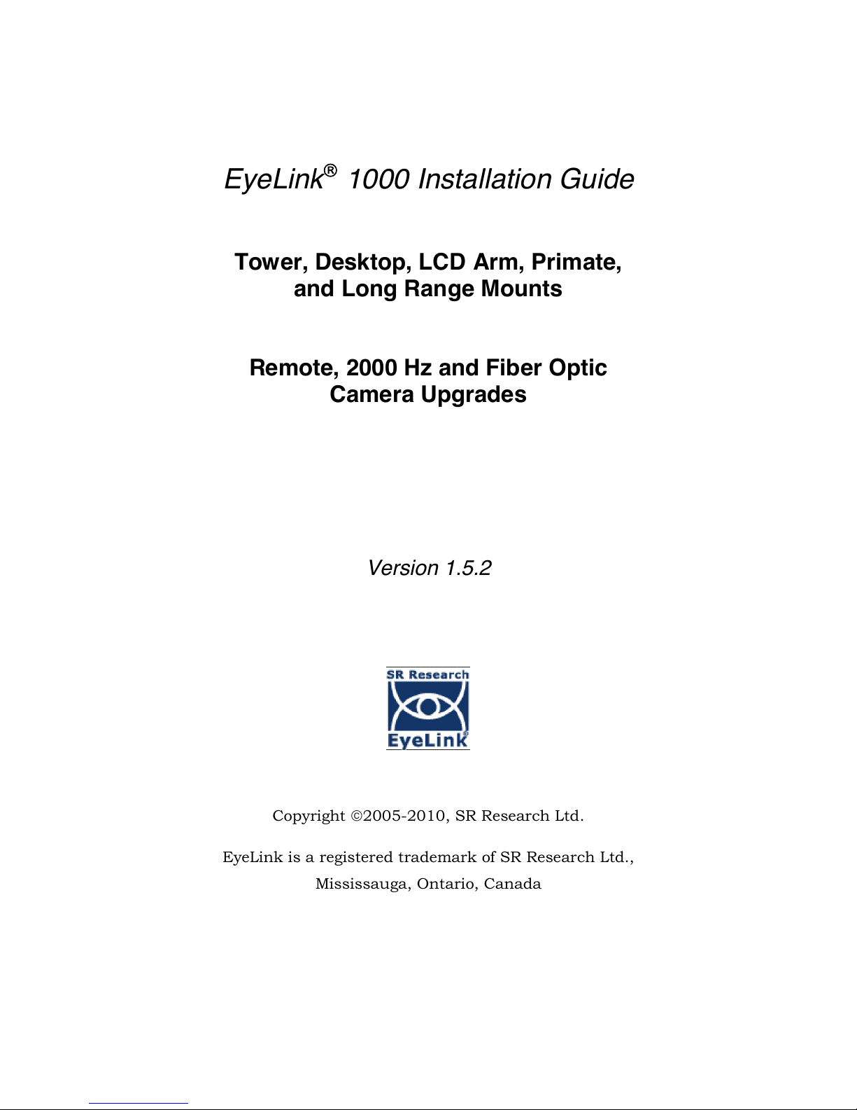
1.1 Suggested Equipment Layout
The layout of the EyeLink 1000 equipment is important if participant setup is to be convenient,
and lighting problems are to be avoided. Before setting up the equipment, check the
arrangement of the room to be used against these suggestions. These will aid in the ease of
acquiring good experimental data.
Ideally, arrange the Host and Display PC monitors on tables in an ‘L’ shape, as in Figure
1-1. This configuration allows the experimenter to adjust the eye tracking device and set up
the subject for the experiment while having access to both computer keyboards and
monitors.
Figure 1-1: Suggested EyeLink 1000 System Layout
If you are using the SR Research chinrest, please make sure you have a sturdy table
available to clamp the chinrest to. This table must have a minimum thickness of 1.8 cm and
a maximum thickness of 8.0 cm. The bottom edge of the table should have a depth of at
least 6.0 cm to mount the integrated table clamp.
Ideally, the table you select should be deep enough to accommodate both the monitor
(especially for a CRT monitor) and eye tracker. For a 21’’ CRT monitor with a 30viewing
angle, the minimum table depth should be about 130 cm. A high table will ensure that even
the tallest participants do not need to hunch over in order for their view to be aligned with
the top of the Display computer’s monitor.

Introduction
2005
-
2010 SR Research Ltd.
3
Avoid windows or other bright light sources that could cause reflections on the host and
display monitors. The grey walls highlighted in Figure 1-1 are locations where bright light
sources will cause reflections.
Supply sufficient light in the room. The best way to light the room is with ceiling-mounted
fluorescent lights, above and no more than two meters behind the computer monitors.
Painting the walls light colors or white will maximize ambient light as well.
Avoid environmental distractions. Be sure the room can be kept quiet, that no distracting
items are viewable by the participant, and so on. It is a good idea to ensure that the
participant cannot see the host monitor without turning their head (discourage this).
Supply a comfortable, stable chair for the participants. It should not wobble or move when
sat in, and the back should be firmly attached to the seat - springiness encourages some
participants to rock forwards and back. A chair with a concave back also discourages
shifting of the body, as does a high back. The top of the chair back should be just below the
shoulders on an average participant. Finally, make sure participants can enter and leave the
chair easily, as the chair will be close to the table with the Display PC monitor.

4Installation and System Cabling
2005-2010 SR Research Ltd.
2. Installation and System Cabling
IMPORTANT:
1. Power off computers before connecting or disconnecting any cables!
Ensure that all cabling is properly connected and connectors are properly
secured to the Host PC and the EyeLink 1000 camera before use.
2. Ensure that the RED switch on the back of the Host PC power supply
(near the on/off switch) matches your country’s voltage! (e.g.,115 or 230 V)
3. Static Electricity Discharge may cause permanent damage to your system.
In order to avoid possible static electricity discharge during installation,
please discharge any static electricity accumulated in your body by touching
a grounded metal surface or the computer case for a few seconds.
2.1 Unpacking
Unpack all of the items you have received from SR Research Ltd. If the system has been stored
or transported at a temperature below 10°C, allow all parts to warm to room temperature
before proceeding.
If you are unpacking the EyeLink 1000 Tower Mount, please be careful as it contains glass that
may have been broken during shipping.
IMPORTANT: The EyeLink 1000 Tower assembly should be held by the
vertical posts and should NEVER be held by the mirror or the
components attached to the mirror.
2.2 Display PC Hardware Installation
Set up the Display PC (the computer to be used to deliver the experiment to the subject and to
control EyeLink 1000 calibration) at the desired location (see Section and Figure 1-1 for a
suggested layout). This includes connecting the keyboard and mouse to the computer, as well
as the power supply and monitor cables.
The requirements for the Display PC depend greatly on the type of experimental paradigms for
which the EyeLink 1000 will be used. For example, gaze contingent paradigms generally
require more computing power than simple cognitive paradigms because the computer display
needs to be updated as quickly as possible. Similarly, video and audio intensive experiments
may need faster hard disks to support the transfer of large video file data to the computer in a
timely manner. The following requirements are suggestions for a Display PC configuration that

Installation and System Cabling
2005
-
2010 SR Research Ltd.
5
should be able to handle most experimental requirements. Please contact a SR Research Ltd.
representative if you have specific questions about your situation and would like our input.
Pentium Core2Duo 2.6 GHz or higher; at minimum your processor should support
Hyperthreading or have multiple cores
80 GB or larger hard disk with 7,200 or higher rpm
256 MB PCIx video card supporting vertical refresh rates of at least100 Hz; for legacy
technology AGP 8X or PCI video cards may suffice
At least 2 GB RAM (more never hurts!)
A DVD-ROM writer for software installation and data backup
32 bit Windows XP or Vista preferred; or MacOS X 10.2 or higher
17” or larger CRT monitor (for valid timing synchronization), that supports vertical
refresh rates of >= 100Hz (10 ms frames) and horizontal refresh rates of at least100 kHz
Ethernet port to connect Display PC to the EyeLink 1000 Host PC
Optional Ethernet card for use on local network (a dedicated Ethernet port is ideal to
connect to the EyeLink 1000 system)
A keyboard and mouse or other pointing device
Free USB ports (if EyeLink Data Viewer/SR Research Experiment Builder is purchased)
2.3 Setting up the Host PC
Most new acquisitions of the EyeLink 1000 include a preconfigured Host PC requiring simple
setup and the attaching of cables.
Set up the Host PC as you would any computer, at the desired location (see Section and Figure
1-1 for a suggested layout). This includes connecting the keyboard and mouse to the computer,
as well as the power supply and monitor cables.
IMPORTANT: Please be sure to use the PS/2 keyboard and mouse
supplied with your Host PC.
If your EyeLink 1000 has a preconfigured Host PC
continue on to section 2.4 to begin attaching cables.
2.3.1 Rebuilding the Host PC
The PC that will host the EyeLink hardware and software must meet certain specifications due
to the nature of the operating system that the EyeLink Host application runs under. As
computer technology is rapidly changing, only systems tested and approved by SR Research
Ltd. can be guaranteed to work.

6Installation and System Cabling
2005-2010 SR Research Ltd.
In the interest of not instructing our customers to purchase computer equipment only to
encounter difficulties with their installation, the reader is directed to consult the web page
http://www.sr-research.com/compatibleHostPCs.html for a list of systems known to be
compatible and accurate when running the EyeLink hardware and software.
If your EyeLink 1000 system did not come with a preconfigured Host PC, or if you are
upgrading or replacing your original Host PC, you should have the following additional
components on hand. These items were supplied with your original EyeLink purchase.
Please follow “Appendix A: Host PC Hardware Installation” to install these hardware
components then continue with the software instructions below.
1. Frame Grabber PCI or PCIe card.
2. DLINK DFE538-TX Ethernet PCI card, or Agere ET131x Gigabit PCIe card.
3. Optional Analog card (if purchased).
4. “SR Research EyeLink CL” CD. Please note that each EyeLink 1000 system requires a
camera-specific .SCD file and therefore, you should use the EyeLink 1000 Installation
CD that comes with your system.
5. “ROM-DOS Boot CD”.
Depending on the operating system that is to be used on your Host PC’s non-EyeLink partition,
you may require the following:
1. “System Commander Boot CD” – originally supplied for customers using Windows XP
on their Host PCs; not required for Vista (see Appendix C).
To install the EyeLink Host software on a computer with Windows XP, follow the instructions in
Appendix B. To install the Host software under Vista, follow the instructions in Appendix C.
Note that for Vista, a clean installation of Vista is required.
2.4 Host PC Wiring
In all cases, connect all cables with the power off, and power up the system once all cabling is
in place.
Figure 2-1: The Standard Camera (left) and Fiber Optic
Camera Base Box and Camera Head (right)

Installation and System Cabling
2005
-
2010 SR Research Ltd.
7
The cable connections required depend upon whether you have the EyeLink 1000 Standard
Camera or the Fiber Optic Camera. The Standard Camera is pictured in the left side of Figure
2-1, while the Fiber Optic Camera components appear in the right side of Figure 2-1.
If you have the Standard Camera, follow the instructions in the next section entitled “Standard
Camera System Installation”. If you have the Fiber Optic Camera then skip to Section 2.4.2
entitled “Fiber Optic Camera System Installation”.
2.4.1 Standard Camera System Installation
2.4.1.1 Standard Camera Pre-installation Checklist
Ensure that you have the listed components available before you start installation:
1. EyeLink 1000 Standard Camera (pictured in the left side of Figure 2-1).
2. EyeLink 1000 Mount. Each type of Mount consists of an infrared illumination source
and an apparatus for holding the EyeLink 1000 camera. Each Mount option has a
separate chapter to be consulted regarding its installation. Mount types for the
Standard Camera include the Desktop, Tower, LCD Arm and Primate Mounts.
3. 12V Power supply for the EyeLink 1000 Standard Camera.
4. CameraLink cable to connect EyeLink 1000 Standard Camera to High-Speed Frame
Grabber card (may be integrated into the LCD Arm Mount).
5. Crossover Ethernet cable to connect Host and Display PC together.
6. EyeLink Host PC – if your system did not come with a preconfigured Host PC, or if you
wish to replace the Host PC, see section 2.3.1 for more information.
You will also need the following components:
1. A power strip with surge protection to ensure that your EyeLink receives consistent
voltage and to make it easy to power the system on and off.
2. A Display PC that ideally meets the required specifications. These specifications are
listed in section 1.3.2.
3. Some tools may be needed to adjust your mount or tighten cabling (usually a Phillips
and/or slotted screwdriver will do).
8Installation and System Cabling
2005-2010 SR Research Ltd.
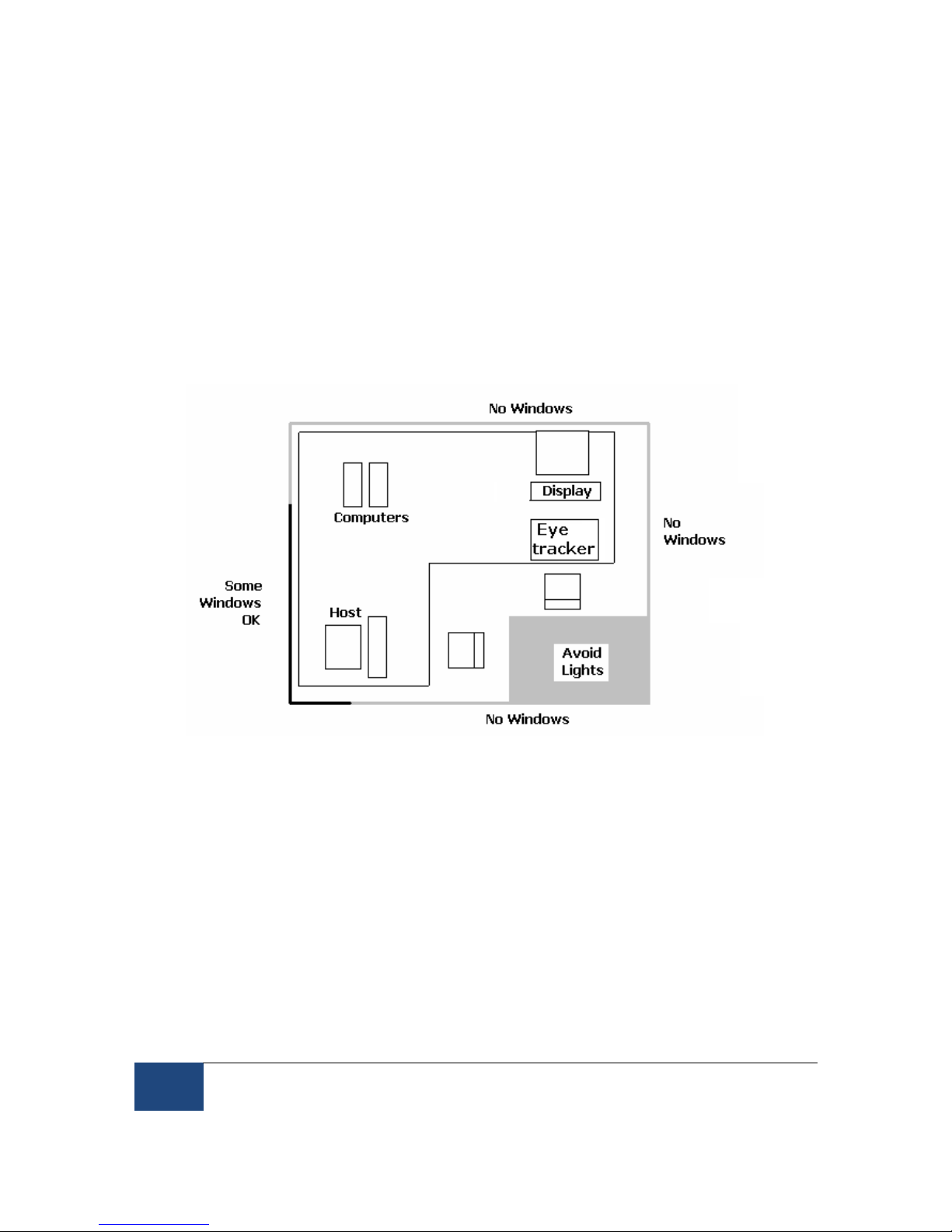
Figure 2-2: Host and Display PC Basic Cabling
2.4.1.2 Standard Camera System Wiring
Standard Camera cabling steps for the Host PC are (see Figure 2-2):
1. If not already completed, attach the keyboards, mouse, power cords, monitors etc. to
the Host and Display PCs.
2. Connect one end of the Ethernet crossover cable provided with your system to the
Ethernet card port on the Host PC marked with an “EyeLink Ethernet” label. Connect
the other end of the cable to the Ethernet port on the Display PC that you will later
configure for use with the EyeLink system. Ensure the cable is securely connected at
both ends.
Do NOT connect the crossover cable to the Ethernet port on the Host PC marked
“LAN/WAN”, which is on the motherboard. This port may be used to access the Internet
when running Windows.
3. Connect one end of the CameraLink Cable provided with your system to the High-speed
Frame Grabber card interface on the back of the Host PC. Ensure the CameraLink cable

Installation and System Cabling
2005
-
2010 SR Research Ltd.
9
is firmly attached with the two thumb screws tightened to lock the cable in place. A
slotted screwdriver may make this task easier.
The other end of the CameraLink Cable will be attached to the Standard Camera once it
is placed in its Mount.
4. Plug the 12V power supply’s small, circular end into the standard EyeLink 1000
camera. Plug the other end of the power supply into a surge protected power source.
The camera is powered as soon as it has an electrical supply, so a power supply with a
switch provides a convenient way to turn the camera on and off.
Continue on to 2.4.4 EyeLink Response Device Installation
10 Installation and System Cabling
2005-2010 SR Research Ltd.
2.4.2 Fiber Optic Camera System Installation
In general, the Fiber Optic Camera Head should be powered before the Camera Base
Box and the Host PC. Should the camera be unresponsive, power off the Camera Head
and then re-power it so that Camera Head is powered before the Camera Base Box.
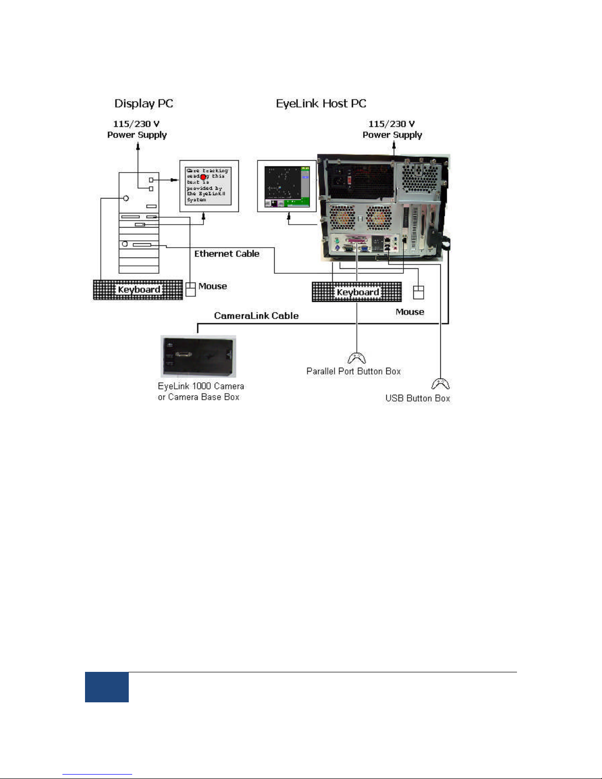
2.4.2.1 Fiber Optic Camera Pre-installation Checklist
Ensure that you have the following listed components before you start installation.
1. EyeLink 1000 Fiber Optic Camera components appear in Figure 2-3. Items ii and iv are
only supplied if setting up the fiber optic camera for use with a Desktop, Tower, Primate
or LCD Arm Mount.
i. Camera Base Box
ii. Camera Adapter (for use with Desktop, Tower, Primate and LCD Arm Mount
options)
iii. Camera Head
iv. Integrated Extension Cable (for use with Desktop, Tower, Primate and LCD Arm
Mounts)
v. Fiber Optic Extension Cable
vi. Fiber Optic Camera 5V power supply with pressure-release connectors
(alternative power sources include a Battery Pack Power System or BNC
connector-based power cable)
Figure 2-3: Fiber Optic Camera Components.

Installation and System Cabling
2005
-
2010 SR Research Ltd.
11
2. EyeLink 1000 Mount. Each type of Mount consists of an infrared illumination source
and an apparatus for holding the EyeLink 1000 camera. Each Mount option has a
separate chapter to be consulted regarding its installation. Mount types for the Fiber
Optic Camera include the Desktop, Tower, LCD Arm, Primate and Long Range Mounts.
3. 12V Power supply for the EyeLink 1000 Fiber Optic Camera Base Box.
4. CameraLink cable to connect Camera Base Box to High-Speed Frame Grabber card.
5. Crossover Ethernet cable to connect Host and Display PC together.
6. EyeLink Host PC – if your system did not come with a preconfigured Host PC, or if you
wish to replace the Host PC, see Section 2.2 for more information.
You will need to supply the following components:
1. A power strip with surge protection to ensure that your EyeLink receives consistent
voltage and to make it easy to power the system on and off.
2. A Display PC that ideally meets the required specifications. These specifications are
listed in section 1.3.2.
3. Some tools may be needed to adjust your mount or tighten cabling (usually a Phillips
and/or slotted/flathead screwdriver will do).
2.4.2.2 Fiber Optic Camera System Wiring
Fiber Optic Camera cabling steps are (see Figure 2-2):
1. If not already completed, attach the keyboards, mouse, power cords, monitors etc. to
the Host and Display PCs.
2. Connect one end of the Ethernet crossover cable provided with your system to the
Ethernet card port on the Host PC marked with an “EyeLink Ethernet” label. Connect
the other end of the cable to the Ethernet port on the Display PC that you will later
configure for use with the EyeLink system. Ensure the cable is securely connected at
both ends.
Do NOT connect the crossover cable to the Ethernet port on the Host PC marked
“LAN/WAN”, which is on the motherboard. This port may be used to access the Internet
when running Windows.
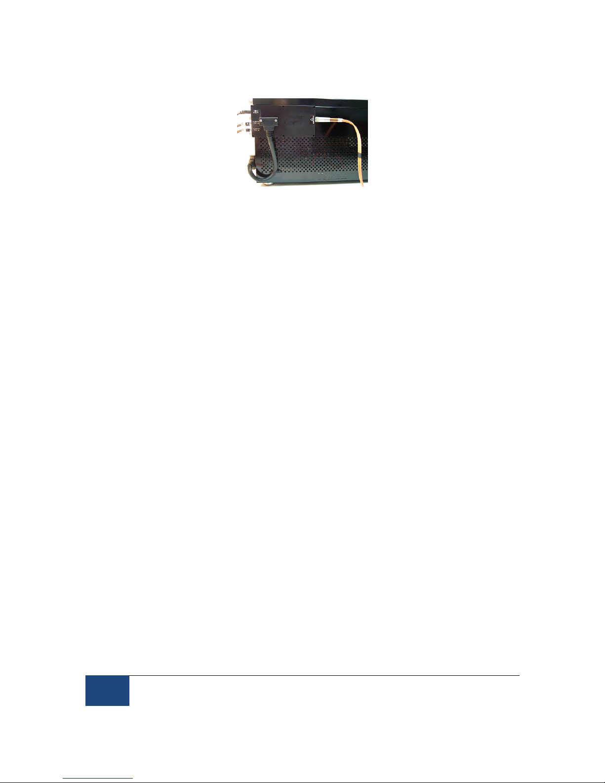
3. Connect one end of the CameraLink Cable provided with your system to the High-Speed
Frame Grabber card interface on the back of the Host PC. Attach the other end of the
CameraLink cable to the Camera Base Box for the Fiber Optic Camera. Affix the Camera
Base Box to the Velcro strips on the rear left side of your Host PC as pictured in Figure
2-4.
Ensure both ends of the CameraLink cable are firmly attached, with the two thumb
screws tightened to lock the cable in place. A slotted screwdriver may make this task
easier.
12 Installation and System Cabling
2005-2010 SR Research Ltd.
Figure 2-4: Camera Base Box and Cabling affixed to the side
of the Host PC
4. Plug the 12V power supply’s small, circular end into the standard EyeLink Camera
Base Box. Plug the other end of the power supply into a surge protected power source.
5. If you are using the Fiber Optic Camera with the Long Range Mount, plug one end of
the Fiber Optic Extension Cable into the Fiber Optic receptacle on the Camera Base
Box. This will be toward the Host PC’s front as pictured in Figure 2-4.
6. If you are using the Fiber Optic Camera with the Desktop, Tower, Primate or LCD Arm
Mount, then locate the Fiber Optic Integrated Extension Cable.
i. Plug the 3.5mm (1/8”) mini-plugs (male, or plug ends) of the Integrated
Extension Cable into the Camera Base Box (female, or socket ends) that should
be affixed to the rear, left, side of the Host PC (see Figure 2-4). The mini-plugs
are marked “R” and “L” and should be plugged into the corresponding marked
sockets on the Camera Base Box, on the rear, beneath the power connector.
ii. Plug the fiber optic connector of the Integrated Extension Cable into the Fiber
Optic receptacle on the Camera Base Box. This will be toward the Host PC’s
front as pictured in Figure 2-4.
iii. The other end of the Integrated Extension Cable will be connected to the fiber
optic cable of the Camera Head and to the illuminator leads from your mount.
Detailed instructions for these connections can be found in the descriptions for
each type of Mount.
2.4.3 The Fiber Optic Camera Adapter
To use the Fiber Optic Camera with the Desktop, Tower, Primate or LCD Arm Mount,
the Camera Head needs to be inserted into a Camera Adapter (see the left side of
Figure 2-5) that makes the Camera Head the same size as the Standard Camera (see
the right side of Figure 2-5). The Camera Adapter can then be inserted in any type of
mount in the place of the Standard Camera.
Follow these steps to insert the Camera Head into the Camera Adapter:
1. Remove the two thumbscrews and crosspiece from the Camera Adapter.
Table of contents
Other SR Research Accessories manuals


