Dinel CLS-23 User manual
Read carefully the instructions published in this manual before the rst use of the level meter. Keep the manual
at a safe place. The manufacturer reserves the right to implement changes without prior notice.
průmyslová elektronika

1 . Basic description .......................................................................................................................4
2 . Variants of sensors ....................................................................................................................5
3 . Dimensional drawing ..................................................................................................................5
4 . Installation and putting into operation ........................................................................................6
5 . Mechanical mounting .................................................................................................................6
6 . Electrical connection ..................................................................................................................9
7 . Settings ......................................................................................................................................11
8 . Function and status indication (only with LED state indicator variant) .......................................12
9 . Order code .................................................................................................................................13
10 . Correct specication examples ................................................................................................13
11 . Accessories ..............................................................................................................................14
12 . Safety, protection, compatibility and explosion proof ...............................................................14
13 . Functional safety ......................................................................................................................15
14 . Use, manipulation and maintenance ........................................................................................15
15. Putting out of operation or disposal ..........................................................................................16
16 . General conditions and warranty .............................................................................................16
17 . Marking of labels ......................................................................................................................17
18. Technical specications............................................................................................................18
19 . Packing, shipping and storage .................................................................................................21
4
© Dinel, s.r.o. CLS–23
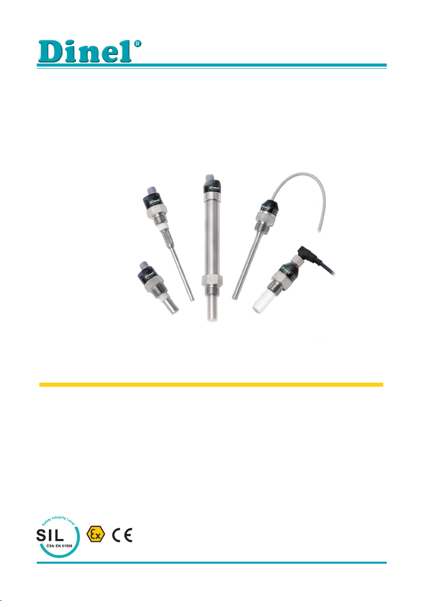
Capacitive level sensors (switches) CLS–23 are designed for limit level detection of electrically
conductive and non-conductive uids in vessels, reservoirs, sumps, pipes, tanks, etc. The
sensitivity of the sensor can be easily set by placing magnetic pen on sensitive spot.
The process coupling at the housing can be with metric thread (M18x1.5 ; M20x1.5), pipe thread
(G3/8” ; G1/2”) or sealing thread (NPT 1/2–14). Output performances – transistor output with
open collector (PNP), two wire electronic switch (S) and NAMUR output for intrinsically safe
connection.
There are next performances available: N – Normal for non-explosive areas, E – Extended
temperature range for non-explosives areas, Xi – Explosion proof (intrinsically safe for explosive
areas), NT – High temperature variant for non-explosives areas and XiT – High temperature
variant for explosive areas.
CLS-23 capacitive level sensors meet the safety integrity level requirements according to
standard EN 61508 at level SIL 1.
* Variant „E“ without LED state indicator
To ensure maximum safety of control processes, we have dened the following safety instructions
and information. Each instruction is labelled with the appropriate pictogram.
This symbol informs you about particularly important instructions for installation and operation of
equipment or dangerous situations that may occur during the installation and operation. Not observing
these instructions may cause disturbance, damage or destruction of equipment or may cause injury.
This symbol indicates particularly important characteristics of the device.
This symbol indicates helpful additional information.
All operations described in this instruction manual have to be carried out by trained personnel
or by an accredited person only. Warranty and post warranty service must be exclusively
carried out by the manufacturer.
Improper use, installation or set-up of the sensor can lead to crashes in the application.
The manufacturer is not responsible for improper use, loss of work caused by either direct
or indirect damage, and for expenses incurred at the time of installation or during the period
of use of the level sensors.

CLS–23 © Dinel, s.r.o.
5
• CLS–23_–10 Uncoated short bar electrode, for sensing the level of electrically non-con-
ductive liquids (oil, crude oil products). Assembly into a side wall of vessel or
into a pipe. Electrode length 30 mm.
• CLS–23_–11 Fully coated short bar electrode, for sensing the level of non-aggressive
electrically conductive liquids (water, water solutions). Electrode insulation
from PP material, assembly into a side wall of vessel or into a pipe. Electrode
length 30 mm.
• CLS–23_–12 Fully coated short bar electrode, for sensing the level of electrically conductive
liquids (various chemicals, moderately aggressive water solutions). Higher
temperature resistance compared to variant "11". Electrode insulation from FEP
material. Assembly into a side wall of vessel or into a pipe. Electrode length
30 mm.
• CLS–23_–20 Partially coated rod electrode, for sensing the level of electrically conductive
and non-conductive liquids, partially resistant against fume condensation in
the sensed area. Electrode insulation from FEP material. Installation from
above, on shorter electrodes (max. 200 mm) also from the side. Electrode
length from 50 mm to 1 m.
• CLS–23_–21 Fully coated rod electrode, universal use, for sensing the level of electrically
conductive liquids. Resistant against fume condensation and partially resistant
against spraying media. Electrode insulation from FEP material. Installation
from above, on shorter electrodes (max. 200 mm) also from the side. Electrode
length from 50 mm to 1 m.
• CLS–23_–30 Dismountable uncoated rod electrode for sensing the level of conductive
or non-conductive liquids. Installation from above, on shorter electrodes (max.
200 mm) also from the side. Electrode length from 50 mm to 1 m.
CLS – 23_ – 10
Thread
Types of threads:
G 3/8''
M18x1,5
M20x1,5
1/2–14 NPT
LED *
CLS – 23_– 11(12) CLS – 23_ –21CLS – 23_ –20
PP (var.:11)
FEP (var.:12)
6
© Dinel, s.r.o. CLS–23
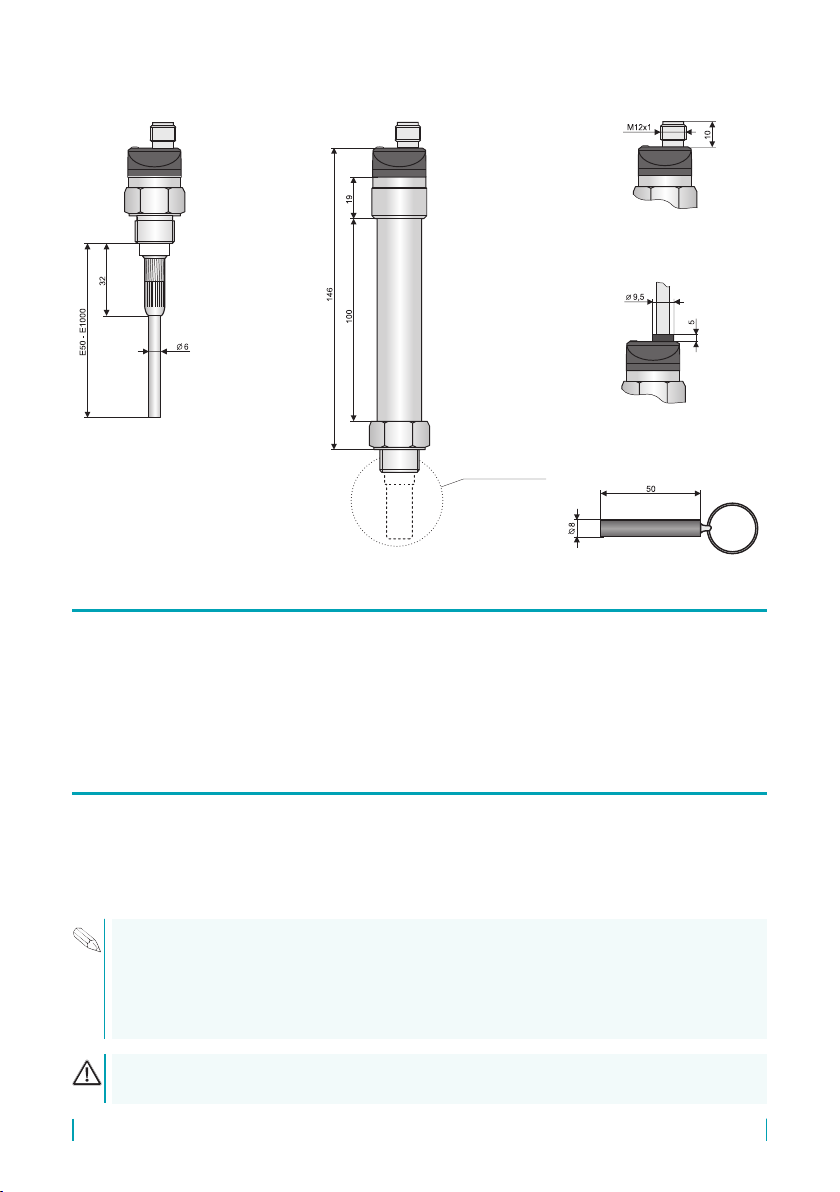
CLS – 23_ – 30
Variant „A“
with cable outlet
Variant „C“ with connector
(outside CLS–23E*)
Magnetic pen MP–8
Electrode type
according to
specic variants
High temperature variants
(CLS–23_T–10; 12; 20; 21; 30)
* Variant „E“ without LED state indicator
• DLS® level sensors can be xed in a vertical, horizontal or slanted position into the wall of
a vessel, storage tank or on a xation console in a sump by screwing into the welding ange,
using a xing nut.
• Basic application recommendations are mentioned below.
During assembly into the metal tank or the storage tank, it is not necessary to separately ground
the base of the level sensor. In case of installation in concrete sumps or silos, it is appropriate to
install the level sensor onto a metallic auxiliary construction (console, lid, etc.), and then connect to
ametallic,constantlysubmerged object, orwithsteelwith steel reinforcementsinconcrete(armouring).
In the case of the reading of an aggressive medium, we recommend that the producer be consulted
If the sensors are tted with protective caps at the ends of the electrodes, remove the caps
before commissioning.
Please follow next 3 steps:
Other manuals for CLS-23
2
Table of contents
Other Dinel Accessories manuals


