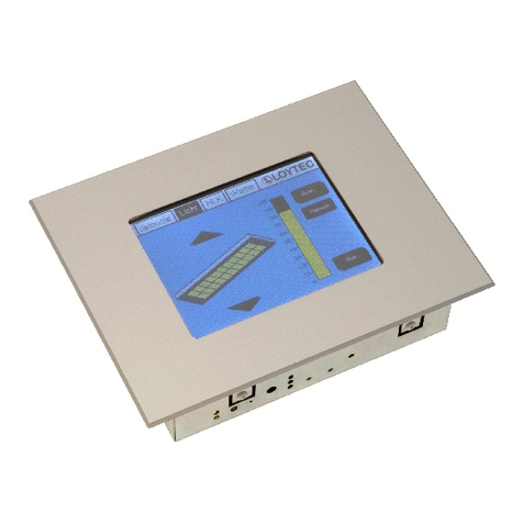
SSD Drives TS8000 Series User manual

TS8000
Link RTN Option
8000/LK/00
HA470411U001 Issue 1
WWW.SDS.LTD.UK | 0117 9381800

© Copyright SSD Drives, Inc. 2005
All rights strictly reserved. No part of this document may be stored in a retrieval system, or
transmitted in any form or by any means to persons not employed by an SSD Drives
company without written permission from SSD Drives, Inc.
Although every effort has been taken to ensure the accuracy of this document it may be
necessary, without notice, to make amendments or correct omissions. SSD Drives cannot
accept responsibility for damage, injury, or expenses resulting there from.
Companies, names and data used as examples herein are fictitious unless otherwise
stated. All trademarks and copyrights are acknowledged as the property of their
respective owners.
WWW.SDS.LTD.UK | 0117 9381800

Table Of Contents TS8000 Option Card
Table of Contents
Product Overview ............................................................................................ 3
General Description ....................................................................................... 3
Safety Information..........................................................................................4
Contents Of Package .....................................................................................4
Specifications .................................................................................................. 5
Power Requirements.......................................................................................5
Serial Communications .................................................................................. 5
Fiber Optic Communications ..........................................................................5
Installation Instructions ..................................................................................... 7
Hardware Diagnostics ...................................................................................... 9
Module LED Status .........................................................................................9
Network LED Status........................................................................................9
Diagnostic Codes......................................................................................... 10
Software Configuration................................................................................... 11
Configuring The Link System......................................................................... 11
Configuring The TS8000 HMI ....................................................................... 13
Version 1.00.00 Page i
WWW.SDS.LTD.UK | 0117 9381800


Product Overview TS8000 Option Card
Product Overview
•Configured with DSD software.
•Noise-free fiber optic interface to any other
devices on the high speed Link network. RS-
232 serial comms interface to the TS8000
HMI.
•24vDC powered by an external supply.
•DIN rail mountable for ease of use.
•Installation and connection hardware
included with card.
General Description
The 8000/LK/00 option card provides a high speed interface (2.7Mbit) between the
TS8000 series HMI and a Link fiber optic network. This module is similar to a 6055/LINK
TechBox, but can be mounted on standard DIN rail instead of being plugged into a drive.
The option card has two fiber optic terminals that accept 1000 micron acrylic fiber. The
transmit strength over the Link network can be adjusted via a 3-position toggle switch. In
addition, the option card also provides a standard RJ-style serial jack for connection to a
TS8000 HMI.
The 8000/LK/00 requires the use of an external 24vDC power supply connected to
terminal block TB1.
Page 3 http://www.SSDdrives.com
WWW.SDS.LTD.UK | 0117 9381800

Product Overview TS8000 Option Card
Safety Information
All safety related regulations, local codes and instructions that appear in the manual or on
equipment must be observed to ensure personal safety and to prevent damage to either
the instrument or equipment connected to it. If equipment is used in a manner not
specified by the manufacturer, the protection provided by the equipment may be impaired.
Do not use the controller to directly command motors, valves, or other process actuators
not equipped with safeguards. To do so can be potentially harmful to persons or
equipment in the event of a fault to the controller.
Contents Of Package
The option card will come shipped with the following additional equipment:
•8000/LK/00 option card.
•Hardware mounting packet.
Page 4 http://www.SSDdrives.com
WWW.SDS.LTD.UK | 0117 9381800

Specifications TS8000 Option Card
Specifications
The following specifications pertain to the TS8000 series option cards. SSD Drives retains
the right to modify specifications at any time, without prior notice.
Power Requirements
Power is supplied to the option card from an external 24vDC supply connected to terminal
block TB1 (200mA rated inrush, 65mA steady state).
Serial Communications
Cable Type: SSD Drives part number CM471054 (Standard TS8000 Comms).
Fiber Optic Communications
Fiber Type: SSD Drives part number CM056316U030.
•Core Diameter: 1000 micron.
•Cable Type: Acrylic.
•Bending Radius: > 1 inch (25.4 mm).
•Insulation: Vinyl > 1kV.
Transmit Strength Settings: Switch SW1.
•Center Position: Low intensity – 0-20 m transmit range (0-66 ft).
•Up Position: Medium intensity – 21-40 m transmit range (67-132 ft).
•Down Position: High intensity – 41-60 m transmit range (133-196 ft).
Page 5 http://www.SSDdrives.com
WWW.SDS.LTD.UK | 0117 9381800


Installation Instructions TS8000 Option Card
Installation Instructions
The following specifications pertain to the TS8000 series option cards. SSD Drives retains
the right to modify specifications at any time, without prior notice.
To install the option card, remove all power and I/O communication cables from the unit.
Snap the 8000/LK/00 onto a standard DIN rail.
Connect the RS-232 cable from the option card to the RS-232 Comms port of the TS8000.
Connect the Receive Fiber into the black connector and the Transmit Fiber into the blue
connector. The fiber optic loop should be closed with the Link network as shown below:
Connect external 24v DC power to both the TS8000 and the 8000/LK/00.
Page 7 http://www.SSDdrives.com
WWW.SDS.LTD.UK | 0117 9381800


Diagnostics TS8000 Option Card
Hardware Diagnostics
Module LED Status
The Module LED (left side) indicates the configuration state of the 8000/LK/00.
LED State Fault Description
Off No Power * External 24v DC power not applied
Slow Flash Initialization Fault * Self test failure
(2 flash/sec) * Module does not have a valid config
Fast Flash Off Link Network * Module was halted by Link
(4 flash/sec) * Module is attempting to go online
* Config problem (L-Error, H-Error, or
duplicate address)
On None * Module config is running and
communicating over the Link network
Network LED Status
The Network LED (right side) indicates the status of the connected Link network.
LED State Fault Description
Off Faulted * Network failure
* Module halted or initializing
On None * Network healthy
* Module peer halted or duplicate address
Note: The Network LED can only be in the On state when the Module LED is On
continuously, indicating that the 8000/LK/00 is ready for external communications.
Page 9 http://www.SSDdrives.com
WWW.SDS.LTD.UK | 0117 9381800

Diagnostics TS8000 Option Card
Diagnostic Codes
The Module LED (left side) indicates the configuration state of the 8000/LK/00.
NCP State Module State Module LED Network LED
0 Initializing Slow Flash Off
1 Config Fast Flash Off
2 Fault Slow Flash See note
3 Fault Fast Flash See note
4 Fault Fast Flash See note
5 Fault Slow Flash See note
6 Stopping --- ---
7 Running On On
8 Running On On
9 Running On Off
A Starting Fast Flash See note
B Starting Fast Flash On
C Fault Fast Flash On
Note: LED state depends on whether the network is active at this node’s receiver..
Page 10 http://www.SSDdrives.com
WWW.SDS.LTD.UK | 0117 9381800

Software Configuration TS8000 Option Card
Software Configuration
This document describes the necessary steps to configure the TS8000 HMI to communicate
RS-232 to a Link network using SSD Drives RTNx protocol. This document is intended for
those users who have a working knowledge of both the DSD and DSI8000 software
packages.
To implement this system, the TS8000 requires a device to act as its gateway to the Link
network. That gateway can either be a 6053/LINK or 6055/LINK TechBox, or it can be a
L5300 Link Rack. This application will use a TS8008 connected serially to a 6055/LINK
TechBox as its gateway (Node 400). The Link network will consist of: the aforementioned
6055/LINK, an L5300 Link Rack (Node 500), and a 690+ AC Drive with a 6055/LINK
TechBox (Node 10). This topology is diagrammed as follows:
For more information on the 605x/LINK TechBox refer to: HA470016 – LINK TechBox
Instruction Manual, and for the L5300 refer to: HA353952 – LINK Rack Installation
Manual.
Configuring The Link System
Programming the Link system requires the use of DSD version 1.21 or later and the
Link Database Class Revision must be at 1238 or greater. Earlier DSD versions do not
have the required files to support communications with the TS8000 HMI. To program
the application, begin a new project with the following Link Templates:
•TS8000TB – this will be the TS8000 gateway (Node 400).
•L5300 – this will be a standard Link2 Rack (Node 500).
•L690Pv5 – this will be a 690+ AC Drive with a Link TechBox (Node 10).
Page 11 http://www.SSDdrives.com
WWW.SDS.LTD.UK | 0117 9381800

Software Configuration TS8000 Option Card
Page 12 http://www.SSDdrives.com
WWW.SDS.LTD.UK | 0117 9381800

Software Configuration TS8000 Option Card
Configuring The TS8000 HMI
1. Configure the Communications.
•Navigate to the Communications section of DSI8000.
•Select the RS-232 Comms Port by selecting it from the tree on the left.
•Select the SSD Drives 890-RTNx driver from the applet at the right.
•Use the Add Additional Device button to create two more devices for the Link
rack and the 690.
•Name each device as appropriate, and set each Destination Node field as
defined above in the Link configuration.
Page 13 http://www.SSDdrives.com
WWW.SDS.LTD.UK | 0117 9381800

Software Configuration TS8000 Option Card
Software Configuration TS8000 Option Card
Page 14 http://www.SSDdrives.com
Page 14 http://www.SSDdrives.com
WWW.SDS.LTD.UK | 0117 9381800

Software Configuration TS8000 Option Card
2. Addressing Link data.
At this point it is important to discuss how data is transferred in a Link network. All
Link data is handled in a “Write-Forward” approach. This means that data must be
sent from the source node to the destination node. Link nodes are not capable of
requesting data to read. The TS8000 HMI does not specifically follow this approach.
The TS8000 is capable of reading data as well as writing it. In addition, from the
TS8000’s perspective, inbound slot numbers must be less than 1024. Because of this
combined architecture, data exchange with the TS8000 will be handled as follows:
How The TS8000 Writes Data To Link – Data going from the TS8000 may be written
to ANY device on the Link network. The individual TS8000 data tag uses the
destination device mapping to specify exactly which node is being written to.
How The TS8000 Reads Data From Link – Data going to the TS8000 may only be
written to the HOST device on the Link network. The TS8000 data tag uses the source
device mapping of the Host to specify exactly where the data is coming from.
Fiber
Fiber
RS-232
Serial Fiber
Fiber
Fiber
Fiber
RS-232
Serial Fiber
Fiber
Page 15 http://www.SSDdrives.com
WWW.SDS.LTD.UK | 0117 9381800

Software Configuration TS8000 Option Card
TS8000 Write Only Tags – Data from the TS8000 may be written to ANY device on the
Link network. In our sample application, this means that the TS8000 may directly
write data to the Host TechBox (Node 400), the L5300 (Node 500), and the 690 Drive
(Node 10). This write data will be available at the destination node through a pre-
defined Input Slot with the appropriate Slot Number. The example below shows both
the TS8000 data tag and the Link Input Slot to send a value to the L5300 (Node 500)
at slot 1:
The Write Only tag uses the L5300 (Node 500) device mapping, since that is the
destination device for the data. It specifies Write Slot 1, since that will be the incoming
data slot that we will program at the L5300.
Page 16 http://www.SSDdrives.com
WWW.SDS.LTD.UK | 0117 9381800

Software Configuration TS8000 Option Card
The L5300 is programmed with the Incoming Slot to receive the data from the TS8000.
This data is passed from the TS8000 via the Host TechBox (Node 400) to the L5300 (Node
500). This data is now available to use as needed in the Link application.
TS8000 Read Only Tags – Data from the TS8000 may be read ONLY from the Host
TechBox (the node you are serially plugged into). Because of this, all read data must be
previously WRITTEN to the Host TechBox from the source node. This read data will be
available from the same pre-defined Output Slot number that was used to send it to the
Host TechBox. In our sample application, this means that the TS8000 may directly read
data from the Host TechBox (Node 400). The example below shows both the Link Output
Slot and the TS8000 data tag to send a value from the L5300 (Node 500) to slot 2 of the
Host TechBox (Node 400):
Page 17 http://www.SSDdrives.com
WWW.SDS.LTD.UK | 0117 9381800

Software Configuration TS8000 Option Card
The L5300 is programmed with the Outgoing Slot to send data to the TS8000. This data
is sent to the Host TechBox (Node 400) and then read serially by the TS8000. You do not
have to explicitly define an Input Slot in the Host TechBox for this data.
The Read Only tag uses the Host (Node 400) device mapping, since that is the source
device for the data. It specifies Read Slot 2, since that is the outgoing data slot that
was programmed at the L5300.
TS8000 Read / Write Tags – TS8000 data is written to the destination L5300 (Node
500), and read from the Host TechBox (Node 400). At the Link level, the data
exchange follows both of the methods described above, and therefore requires an
Input Slot mapping and an Output Slot mapping. The example below shows both the
Link Input and Output Slots and the TS8000 data tag to read and write a value with
the L5300 (Node 500):
Page 18 http://www.SSDdrives.com
WWW.SDS.LTD.UK | 0117 9381800
Table of contents
