Star Lake ETR1500 User manual
User’s Manual
Revision Date: June. 15. 2020
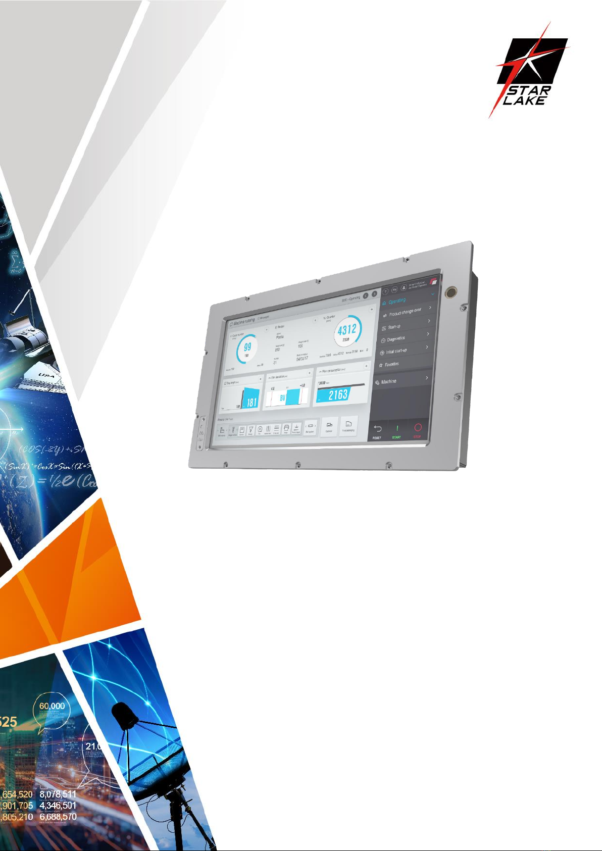
ETR1500
EN50155 Certified
INTEL® Apollo Lake Series (N4200, N3350)
1x LAN (M12),1X USB w/ protect cover
DC-in Voltage: 110Vcc (70-144Vcc)
66-160Vcc for 0.1sec without malfunction and failure
Highly sensitive P-CAP Touch w/ glove usage
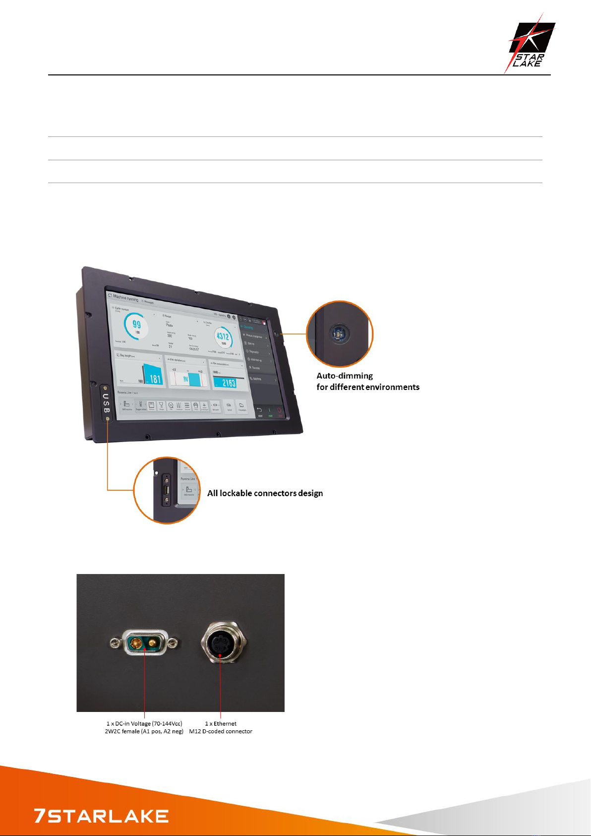
Auto-dimming adjustment
Super contrast ratio 1500:1
Support Slackware and Porteus
Railway Panel computer

ETR1500 User’s Manual
Revision Date: June. 15. 2020
1
Safety Information
Electrical safety
To prevent electrical shock hazard, disconnect the power cable from the electrical outlet before relocating the
system.
When adding or removing devices to or from the system, ensure that the power cables for the devices are
unplugged before the signal cables are connected. If possible, disconnect all power cables from the existing
system before you add a device.
Before connecting or removing signal cables from the motherboard, ensure that all power cables are unplugged.
Seek professional assistance before using an adapter or extension cord. These devices could interrupt the
grounding circuit.
Make sure that your power supply is set to the correct voltage in your area.
If you are not sure about the voltage of the electrical outlet you are using, contact your local power company.
If the power supply is broken, do not try to fix it by yourself. Contact a qualified service technician or your local
distributor.
Operation safety
Before installing the motherboard and adding devices on it, carefully read all the manuals that came with the
package.
Before using the product, make sure all cables are correctly connected and the power cables are not damaged. If
you detect any damage, contact your dealer immediately.
To avoid short circuits, keep paper clips, screws, and staples away from connectors, slots, sockets and circuitry.
Avoid dust, humidity, and temperature extremes. Do not place the product in any area where it may become
wet.
Place the product on a stable surface.
If you encounter any technical problems with the product, contact your local distributor
Statement
All rights reserved. No part of this publication may be reproduced in any form or by any means, without prior
written permission from the publisher.
All trademarks are the properties of the respective owners.
All product specifications are subject to change without prior notice

ETR1500 User’s Manual
Revision Date: June. 15. 2020
2
Table Contents
Safety Information
Chapter 1: Product Introduction
1.1 Specifications
1.2 Front i/o Placement
1.3 rear i/o Placement
1.3 Mechanical Dimension
Chapter 2: IO Introduction
2.1 USB 2.0 x1 (w/ Waterproof Cover)
2.2 2W2C female (A1 pos, A2 neg), 4-40 UNC threaded insert
2.3 M12 D-coded connector
Chapter 3: AUTO DIMMING
Chapter 4:Wall MOUNTING
Chapter 5: BIOS Setup

ETR1500 User’s Manual
Revision Date: June. 15. 2020
3
Safety Information
Electrical safety
To prevent electrical shock hazard, disconnect the power cable from the electrical outlet before relocating the
system.
When adding or removing devices to or from the system, ensure that the power cables for the devices are
unplugged before the signal cables are connected. If possible, disconnect all power cables from the existing
system before you add a device.
Before connecting or removing signal cables from the motherboard, ensure that all power cables are unplugged.
Seek professional assistance before using an adapter or extension cord. These devices could interrupt the
grounding circuit.
Make sure that your power supply is set to the correct voltage in your area.
If you are not sure about the voltage of the electrical outlet you are using, contact your local power company.
If the power supply is broken, do not try to fix it by yourself. Contact a qualified service technician or your local
distributor.
Operation safety
Before installing the motherboard and adding devices on it, carefully read all the manuals that came with the
package.
Before using the product, make sure all cables are correctly connected and the power cables are not damaged. If
you detect any damage, contact your dealer immediately.
To avoid short circuits, keep paper clips, screws, and staples away from connectors, slots, sockets and circuitry.
Avoid dust, humidity, and temperature extremes. Do not place the product in any area where it may become
wet.
Place the product on a stable surface.
If you encounter any technical problems with the product, contact your local distributor
Statement
All rights reserved. No part of this publication may be reproduced in any form or by any means, without prior
written permission from the publisher.
All trademarks are the properties of the respective owners.
All product specifications are subject to change without prior notice

ETR1500 User’s Manual
Revision Date: June. 15. 2020
4
Chapter 1: Product Introduction
1.1 Specifications
System
CPU
INTEL® Apollo Series (N4200, N3350)
Memory type
Up to 8 GB
Storage
mSATA Up to 1TB
Display
Size
15.6
Resolution
1920 *1080
Contrast Ratio
1500:1
Aspect Ratio
16:9
AUTO DIMMING
Light Sensor
Min 20 nits~400 nits w/ modulated automatically or be controlled by SW
Surrounding
Environment
Light Sensor Value
LCD Dimming Level
Tunnel (0~26 Lux)
0~50
23%~37%
Indoor (200~300 Lux)
200~300
72%~80%
Outdoor cloudy
(1000 Lux)
1000
88%~100%
Outdoor sunny
(2000 Lux up)
1200 up
100%
audio
SPK
1 (>75dbA @30cm)
front I/O
USB
USB 2.0 x1 (w/ Waterproof Cover)
Rear I/O
DC
2W2C female (A1 pos, A2 neg), 4-40 UNC threaded insert
Ethernet
M12 D-coded connector
Environment
Certification
EN50155 T3 class (-25 °C+70°C),
ETR1500 User’s Manual
Revision Date: June. 15. 2020
5
Shock and Vibration according to EN 61373 class B category 1
IEC 60605, EN50121-3-2
Applications, Operating System
Applications
Train journey, entertainment contents and commercial advertisements.
Operating System
Windows 10 64 Bit, Ubuntu13.04, Ubuntu13.10, Ubuntu14.04, Fedora20
Full compatible to Slackware and Porteus Linux distribution 4.14.29
1.2 Front IO Placement
1.3 Rear IO Placement

ETR1500 User’s Manual
Revision Date: June. 15. 2020
6
1.4 Mechanical dimension
Mechanical Dimensions
ETR1500 User’s Manual
Revision Date: June. 15. 2020
7
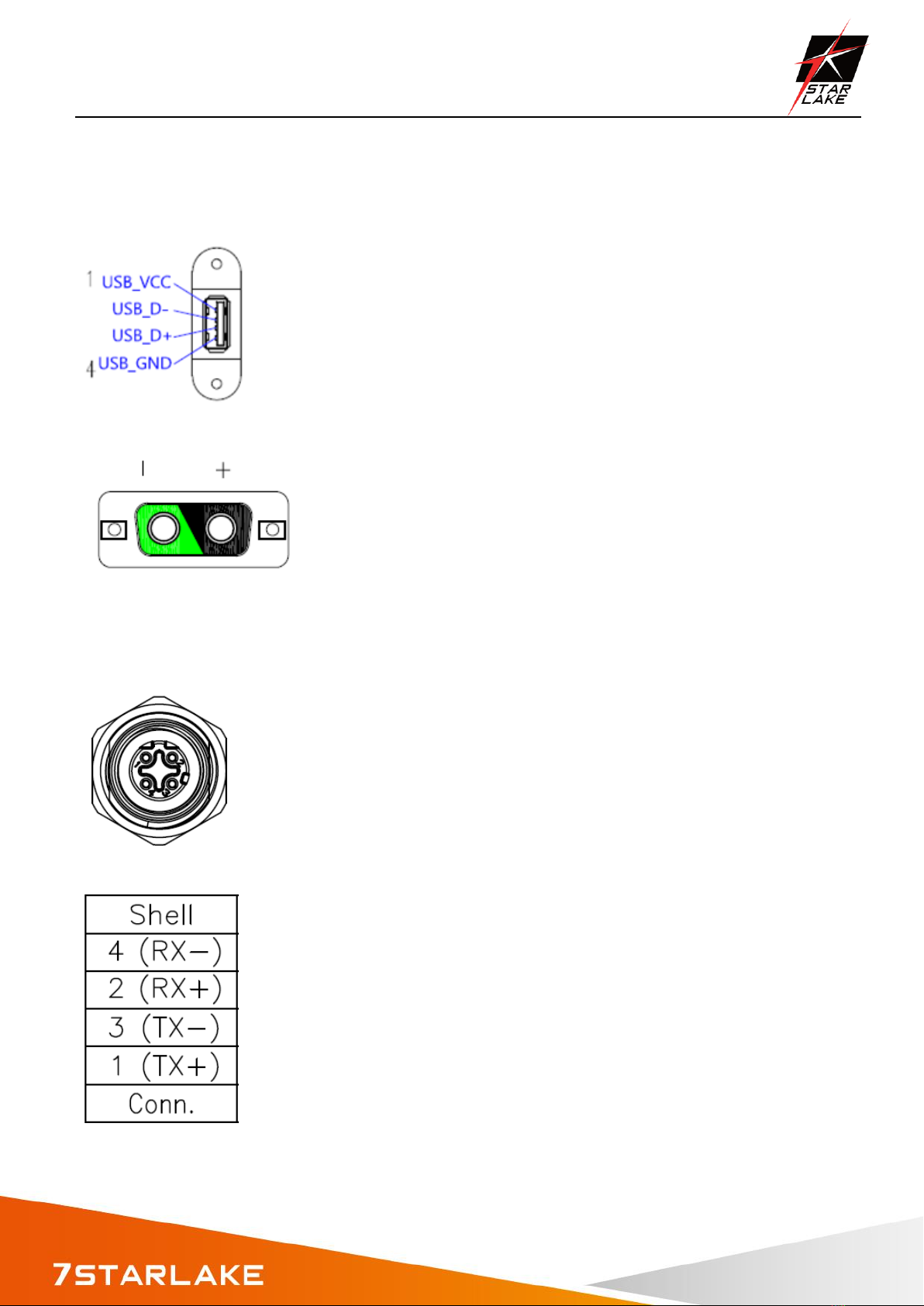
Chapter 2: IO INTRODUCTION AND PIN ASSIGEMENT
2.1 USB 2.0 x1 (w/ Waterproof Cover)
2.2 2W2C female (A1 pos, A2 neg), 4-40 UNC threaded insert
2.3 M12 D-coded connector

ETR1500 User’s Manual
Revision Date: June. 15. 2020
8
Chapter 3: Auto Dimming
Because the human eye perceiving brightness is nonlinear, PWM duty must be set percentage at
each stage of opening and closing
LCD Backlight:
Level 10 = 100%
Level 9 = 91%
Level 8 = 82%
Level 7 = 73%
Level 6 = 64%
Level 5 = 55%
Level 4 = 46%
Level 3 = 37%
Level 2 = 28%
Level 1 = 19%
Level 0 =10%
Auto dimming level
Surrounding environment
Light Sensor value
LCD dimming level
Tunnel (0~26 Lux)
0~50
23%~37%
Indoor (200~300 Lux)
200~300
72%~80%
Outdoor cloudy
(1000 Lux)
1000
88%~100%
Outdoor sunny
(2000 Lux up)
1200 up
100%

ETR1500 User’s Manual
Revision Date: June. 15. 2020
9
Chapter 4: WALL MOUNT
The ETR1500 can be panel mounted using 10 countersunk M4 screws and Nut. Make sure there is adequate
space behind the panel for ventilation and I/O connectors, and that the panel material and thickness can
support the weight of the device.

ETR1500 User’s Manual
Revision Date: June. 15. 2020
10
Chapter 5: BIOS Setup
Once you enter the Aptio Setup Utility, the Main Menu will appear on the screen. The
Main Menu allows you to select from several setup functions and exit choices. Use the
arrow keys to select among the items and press <Enter> to accept and enter the
sub-menu.
5.1 Main Page
This section allows you to record some basic hardware configurations in your computer
and set the system clock.
5.2 Advance Menu

ETR1500 User’s Manual
Revision Date: June. 15. 2020
11
This section allows you to configure your CPU and other system devices for basic operation
through the following sub-menus.
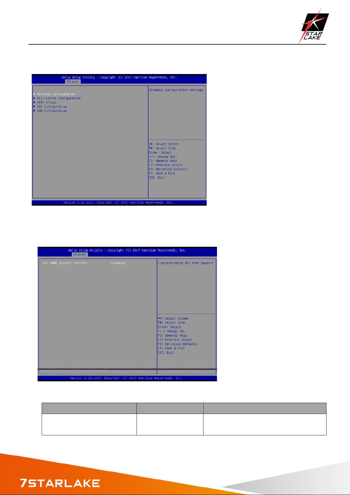
5.3 Chipset

ETR1500 User’s Manual
Revision Date: June. 15. 2020
12
5.3.1North Bridge
Item
Option
Description
Max TOLUD
2 GB[Default]
2.25 GB
2.5 GB
2.75 GB
Maximum Value of TOLUD.
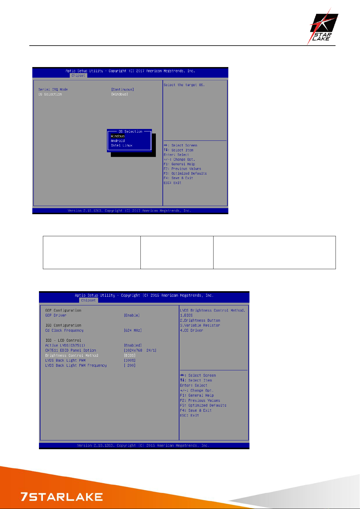
5.3.1SOUTH Bridge
Item
Option
Description
Serial IRQ Mode
Quiet
Continuous[Default]
Configure Serial IRQ Mode.
OS Selection
Windows[Default]
Android
Intel Linux
Select the target OS.
ETR1500 User’s Manual
Revision Date: June. 15. 2020
13
OS Selection
Windows[Default]
Android
Intel Linux
Select the target OS.
5.4 Uncore configuration

ETR1500 User’s Manual
Revision Date: June. 15. 2020
14
Item
Option
Description
GOP Driver
Enable[Default]
Disable
Enable GOP Driver will unload VBIOS;
Disabled it will loadVBIOS.
Cd Clock Frequency
144 MHz
288 MHz
384 MHz
576 MHz
624 MHz[Default]
Select the highest Cd Clock frequency
supported by the platform.
Active LVDS (Ch7511)
Disabled[Default]
Enabled
Active Internal
LVDS(eDP->Ch7511-to-LVDS).
CH7511 EDID Panel Option
1024x768 24/1[Default]
800x600 18/1
1024x768 18/1
1366x768 18/1
1024x600 18/1
1280x800 18/1
1920x1200 24/2
1920x1080 18/2
1280x1024 24/2
1440x900 18/2
1600x1200 24/2
1366x768 24/1
1920x1080 24/2
1680x1050 24/2
Port1-EDP to LVDS(Chrotel 7511) Panel
EDID Option.
Brightness Control Method
BIOS[Default] BR
Button
VR
OS Driver
LVDS Brightness Control Method. 1.BIOS
2.Brightness Button 3.Variable Resistor
4.OS Driver.
LVDS Back Light PWM
00%
25%
50%
75%
100%[Default]
Select LVDS back light PWM duty.
ETR1500 User’s Manual
Revision Date: June. 15. 2020
15
5.5 South cluster configuration
5.6 SCC configuration
Item
Option
Description
SCC eMMC Support (D28:F0)
Disable[Default],
Enable
Enable/Disable SCC eMMC Support.
ETR1500 User’s Manual
Revision Date: June. 15. 2020
16
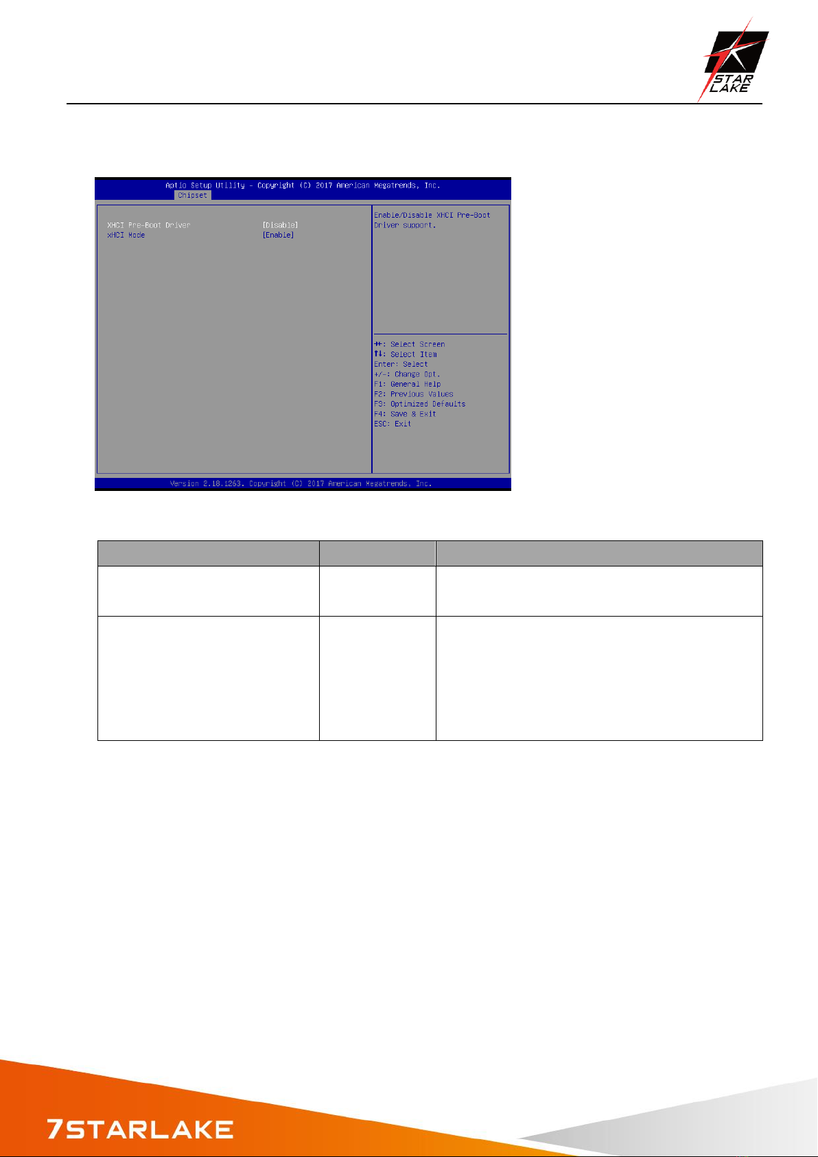
5.7 usb configuration
Item
Option
Description
XHCI Pre-Boot Driver
Enable,
Disable[Default]
Enable/Disable XHCI Pre-Boot Driver support.
XHCI Mode
Enable[Default]
Disable
Once disabled, XHCI controller would be
function disabled, none of the USB devices ae
detectable and usable during boot and in OS.
Do not disable it
unless for debug purpose.
Table of contents


