SSI A20829 User manual

Single Gas H2(Hydrogen)
Sensor Modules
With Optional O2Input
OPERATIONS MANUAL
Super Systems Inc.
7205 Edington Drive
Cincinnati, OH45249
513-772-0060
Fax: 513-772-9466
www.supersystems.com
PN: A20829
PN: A20830

Super Systems Inc.
Page 2 of 38
Super Systems Inc.
USA Office
Corporate Headquarters:
7205 Edington Drive
Shipping Address:
7245 Edington Drive
Cincinnati, OH 45249
Phone: (513) 772-0060
http://www.supersystems.com
Super Systems Europe
Unit E, TyburnTrading Estate,
Ashold Farm Road, Birmingham
B249QG
UNITED KINGDOM
Phone: +44 (0) 121 306 5180
http://www.supersystemseurope.com
Super Systems México
SistemasSuperioresIntegrales S de RL de CV
Acceso IV No. 31 Int. H Parque Industrial
Benito Juarez
C.P. 76120 Querétaro, Qro.
Phone: +52 442 210 2459
http://www.supersystems.com.mx
Super Systems China
No. 369XianXia Road
Room 703
Shanghai, CHINA
200336
Phone: +86 21 5206 5701/2
http://www.supersystems.cn
Super Systems India Pvt. Ltd.
A-26 Mezzanine Floor, FIEE Complex,
OkhlaIndl. Area, Phase –2
New Delhi, India 110 020
Phone: +91 11 41050097
http://www.supersystemsindia.com

Single Gas Sensor Module (SGSM)
Operations Manual
Super Systems Inc.
Page 3 of 38
Page 3 of 51
Table of Contents
Introduction..................................................................................................................................... 4
Specifications.................................................................................................................................. 4
Connections Diagram ..................................................................................................................... 5
A20829 ......................................................................................................................................... 5
A20830 ......................................................................................................................................... 6
Connection Ports & Function ...................................................................................................... 6
Mounting ......................................................................................................................................... 7
A20829 ......................................................................................................................................... 7
A20830 ......................................................................................................................................... 8
Modbus............................................................................................................................................ 8
A20829 ......................................................................................................................................... 8
A20830 ......................................................................................................................................... 9
Modbus Registers ..........................................................................................................................10
Initial Network Configuration ........................................................................................................18
nLocateIP Method ......................................................................................................................18
Control Interface via Web Browser................................................................................................20
Main............................................................................................................................................21
Instrument Information..............................................................................................................21
Sensor Information ....................................................................................................................22
Instrument Configuration...........................................................................................................23
Output Configuration..................................................................................................................23
Output Calibration ......................................................................................................................25
Sensor Calibration......................................................................................................................26
A20829 ....................................................................................................................................26
A20830 ....................................................................................................................................28
Input Configuration ....................................................................................................................30
Zero & Span Calibration: ........................................................................................................30
TC Trim ...................................................................................................................................30
CJ Trim ...................................................................................................................................31
Alarms........................................................................................................................................31
SSI Configuration .......................................................................................................................32
Read/Write Registers.................................................................................................................33
Network Configuration...............................................................................................................34
Replacement Parts ........................................................................................................................35

Single Gas Sensor Module (SGSM)
Operations Manual
Super Systems Inc.
Page 4 of 38
Page 4 of 51
Warranty.........................................................................................................................................36
Appendix A: DIP Switch Setting Examples.....................................................................................37
Revision History .............................................................................................................................38
Introduction
SSi provides hydrogen gas analysis technology for use in heat treating and other industrial
environments. This manual covers the two H2versions of Single Gas Sensor Module (SGSM).
The in-situ H2sensor (A20829) is designed to mount directly to a vertical pipe on a furnace,
while the flow-through sensor (A20830) is designed to be mounted on DIN rail. For compliance
with electrical connection standards, the in-situ H2sensor functions are routed to a 10-Position
plug and an included connection cable. The connections for the DIN mounted flow-through
sensor are on terminal blocks located on the face of the sensor.
The primary function of each of these sensors is to measure H2, but each of them has the ability
to measure Oxygen (O2) with the addition of an external O2sensor (see details below). Note that
the Lambda O2sensor requires 12 VDC power.
Specifications
Specifications
In-Situ H2
Din Rail Mount H2
Part Number
A20829
A20830
24VDC (10-30VDC Acceptable) Power
Input
Yes
Yes
Analog Outputs (4-20mA or 0-5VDC)
2
2
Ethernet
1
1
USB Host port
0
1
USB Client port
0
1
RS485 Communications Ports (modbus
RTU)
1
2
Communications Port for HMI
0
1
Wiring Method
Cable (included)
Direct
Inputs for Optional Oxygen Sensor
Yes
Yes
Measurement Range
0 –100% of gas concentration
Accuracy
±1% of full scale (±0.1% of gas concentration,
based on 100%)
Resolution
0.1%
Response Time (to 90% of Reading)
0 - 6 seconds
Maximum Operating Temperature
122 °F (50 °C)
Field Calibration
Via web interface
Measurement Method
Thermal Conductivity
Specifications
Optional Oxygen Sensor
Part Number
31435
Measurement Range
0 - 21%
Accuracy
±0.1%
Measurement Method
Lambda Zirconia
Single Gas Sensor Module (SGSM)
Operations Manual
Super Systems Inc.
Page 5 of 38
Page 5 of 51
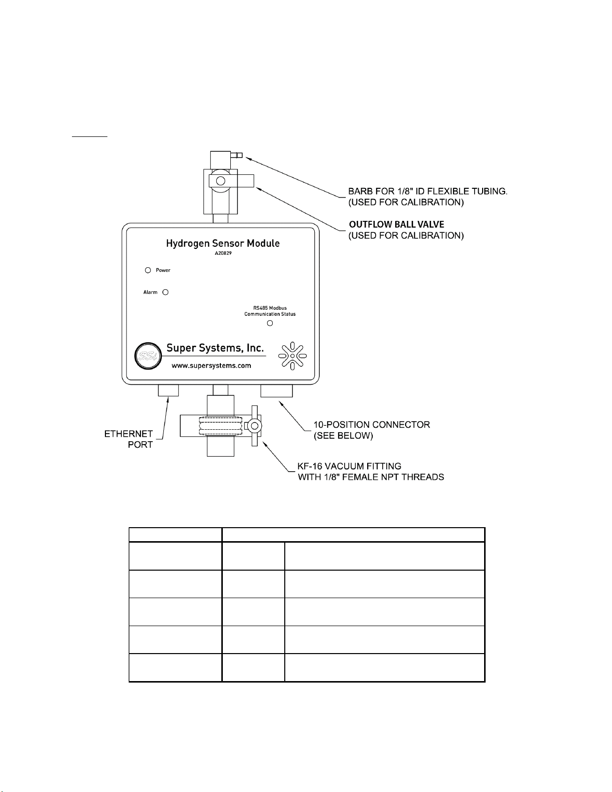
Connections Diagram
The following diagrams show the connections for the two versions of the SGSM.
A20829
Figure 1 - Connections diagram for A20829
.
Wire Color
Red +VDC Power supply (24VDC @ 750 mA)**
Black -VDC
Green/Black Stripe +RS485 Communications signal
Red/Black Stripe -RS485 provided by modbus over serial
White/Black Stripe +O2 O2 input for lambda probe
Orange/Black Stripe
-O2 when used as H2/O2 sensor
Orange + mA Analog output #1
Blue - mA (4-20 mA)
Green + mA Analog Output #2
White - mA (4-20 mA)
Function
Single Gas Sensor Module (SGSM)
Operations Manual
Super Systems Inc.
Page 6 of 38
Page 6 of 51
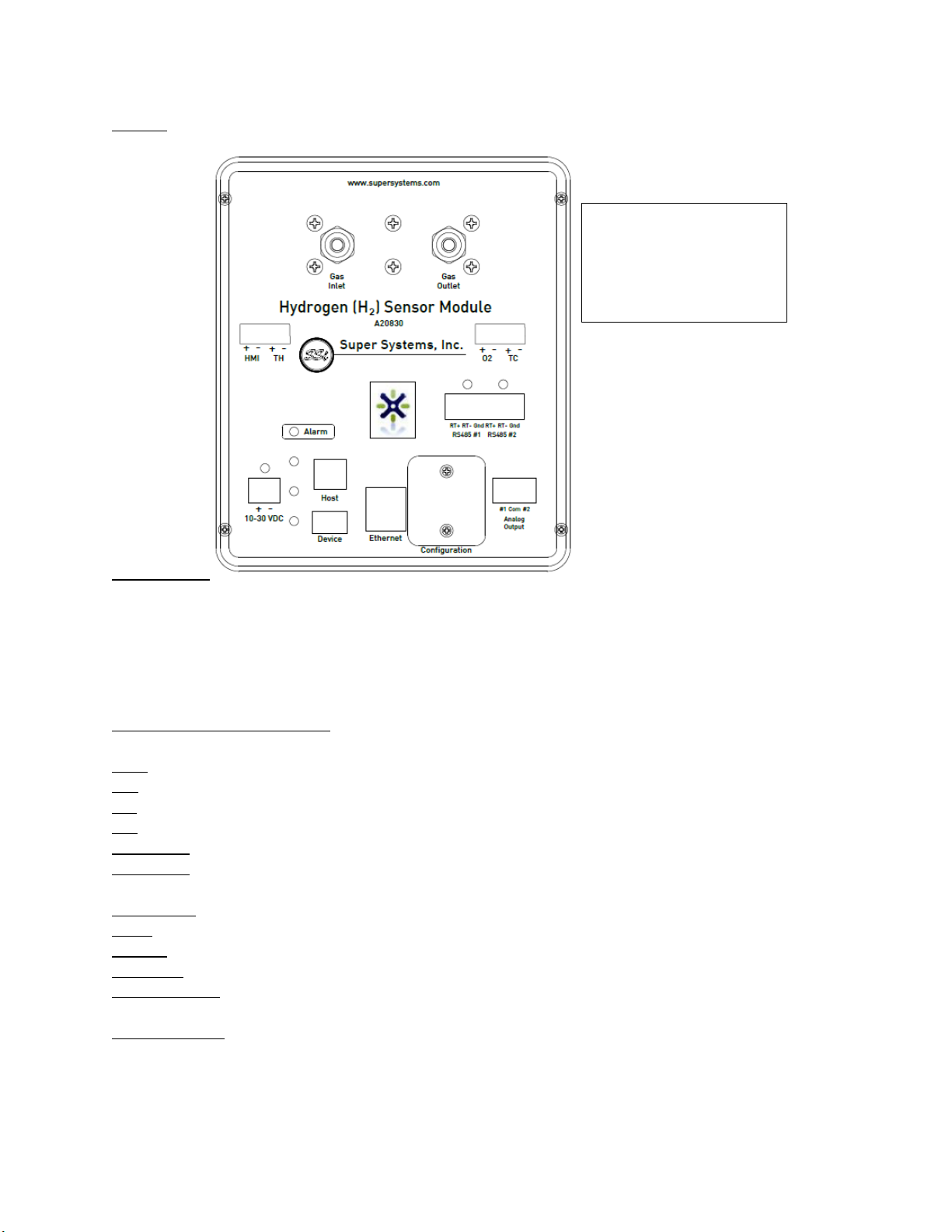
A20830
Figure 2 - Connections diagram for A20830
**Note that both the A20829 and A20830 will accept 10 –30 VDC power. They are commonly
powered using a 24 VDC supply. When a Lambda O2sensor is required, consider using a 12 VDC
supply for both the SGSM and the Lambda sensor. SSi offers a 12 VDC supply for this option.
Connection Ports & Function
HMI: This is the connection for an HMI.
TH: This connection port is N/A for this product.
O2: This is the port for the Lambda O2analog sensor.
TC: This connection port is N/A for this product.
RS485 #1: This is a communications port used for when this device is the Client.
RS485 #2: This is a communications port used for when this device is the Host to another
device.
10-30 VDC: This is the port to supply power to the SGSM.
Host: This is the USB Host port.
Device: This is the USB Client port.
Ethernet: This is the Ethernet port.
Configuration: This is where dip switch settings can be changed for the Modbus
communications address.
Analog Output: These ports are for analog output #1 and #2.
All connection points
are located on the front
of the unit and labeled
with the connection
type and polarity.
Single Gas Sensor Module (SGSM)
Operations Manual
Super Systems Inc.
Page 7 of 38
Page 7 of 51
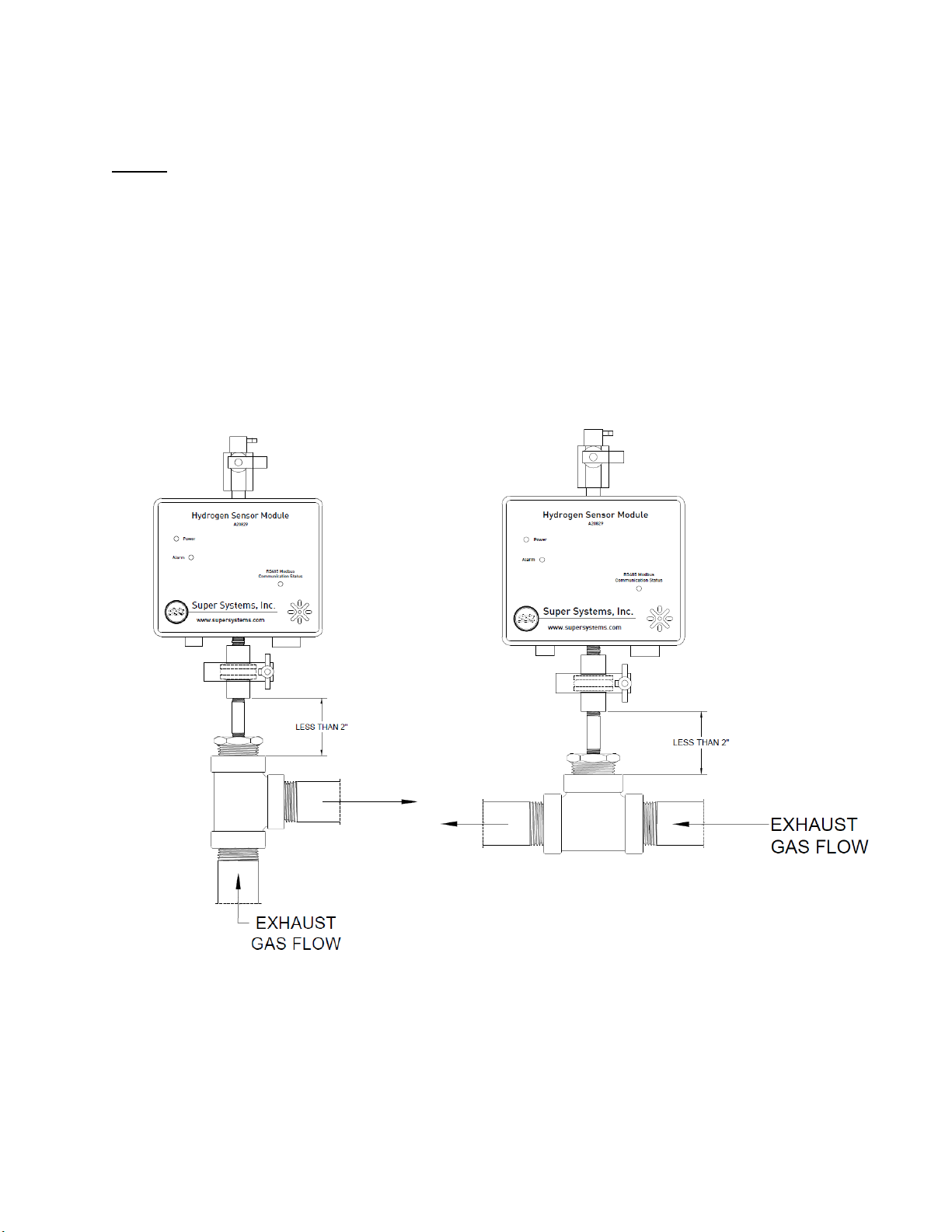
Mounting
A20829
SSi recommends that the in-situ H2sensor (A20829) be mounted to the exhaust piping as close
to the furnace as possible. Many contaminants solidify when cooled and can cause irreversible
damage to the sensor over time. Heat from the gases will help to prevent the formation of
contaminants in the sensor.
The unit should be mounted right side up so that the lettering on the front of the unit can be
read. The length of pipe between the main exhaust and the bottom of the KF fittings should be
minimized and must be
less than 2”
or the unit’s response and accuracy may be negatively
affected. The best location on the exhaust piping is at an elbow where the exhaust line might be
vertically plumbed out of the furnace lid. See illustrations.
Figure 3–Mounting/Plumbingdiagram for A20829
Other mounting locations are possible, but must be tested and verified prior to using for
measurement and control of the furnace atmosphere. Contact SSi if there are questions about
the mounting location.
Single Gas Sensor Module (SGSM)
Operations Manual
Super Systems Inc.
Page 8 of 38
Page 8 of 51
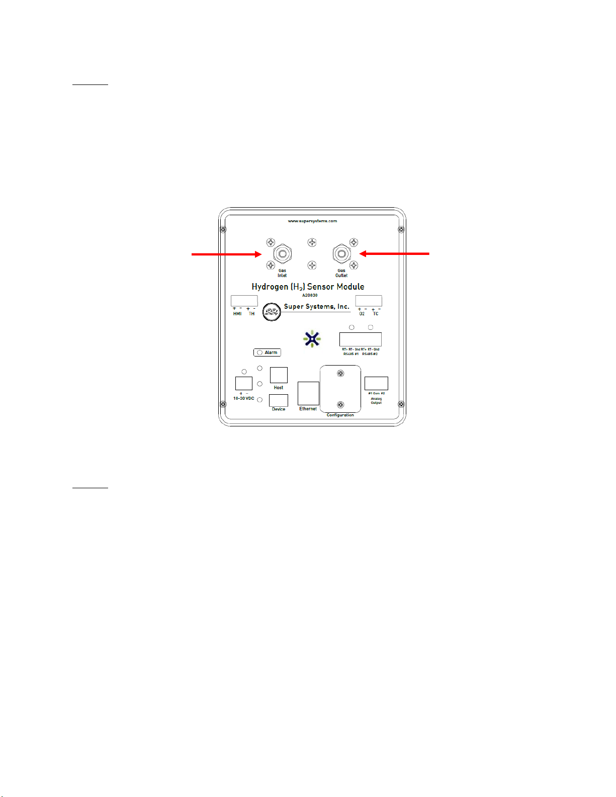
A20830
The flow-through sensor (A20830) requires gas flow past the sensor. The unit has specific inlet
and outlet ports, which are labeled on the unit and shown in the figure below.
The unit comes with 1/8” FNPT threaded ports in which two stainless steel compression fittings
have been plumbed. The compression fittings are sized to handle ¼” OD tubing.
This unit is designed to be mounted to 35 mm DIN rail.
Figure 4 –Connections diagram for A20830
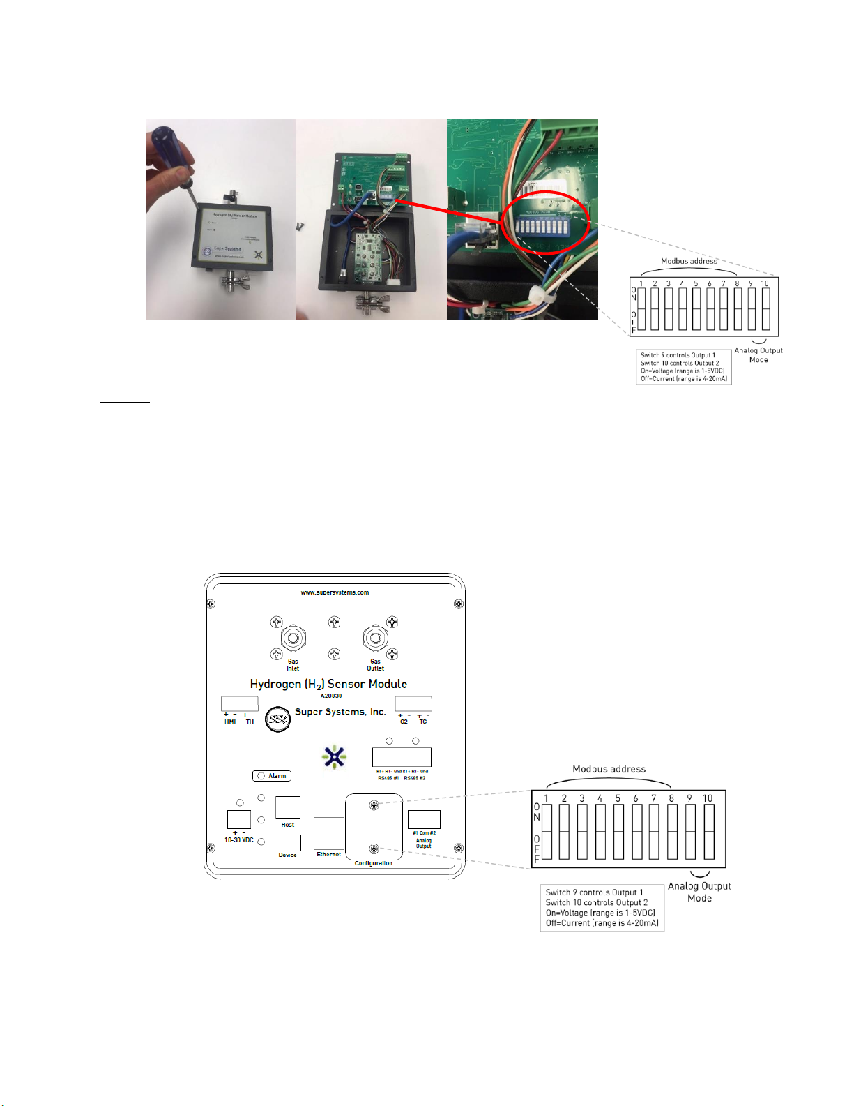
Modbus
A20829
The in-situ H2sensor has DIP switches located inside of the enclosure for setting the Modbus
address. The Modbus address is set to 1 by default. Photos below show where the DIP switches
are located inside of the enclosure. The DIP switch settings for each address are given in
Appendix A.
To gain access to the DIP switches:
1. Verify that the unit is not powered. Unplug the power connector to remove power.
2. Remove the four (4) 6-32 screws to remove the front cover plate.
3. Carefully, pull the cover plate off of the enclosure. The cover plate has a circuit board
attached to it, which is connected to the enclosure via several wires. Be careful not to
damage the wires or circuit boards.
4. The DIP switches are located on the circuit board mounted to the back of the cover plate.
5. Move the DIP switches accordingly for the Modbus address listed in Appendix A.
6. When reassembling the unit, be careful of wire locations. Some wires may need to be
positioned to the side or behind circuit boards in the enclosure in order to get the cover
plate on the enclosure properly.
Single Gas Sensor Module (SGSM)
Operations Manual
Super Systems Inc.
Page 9 of 38
Page 9 of 51
Figure 5 –Modbus DIP switch location for A20829
A20830
The DIP switches are accessible from the front of the unit without having to remove the cover
plate.
1. Verify that the unit is not powered. Unplug the power connector to remove power.
2. Remove the two (2) 6-32 screws from the access plate labeled, “Configuration.” This
will expose the DIP switches.
3. Move the DIP switches accordingly for the Modbus address listed in Appendix A.
4. Secure the cover plate with the two screws.
Figure 6–Modbus DIP switch location for A20830

Single Gas Sensor Module (SGSM)
Operations Manual
Super Systems Inc.
Page 10 of 38
Page 10 of 51
Modbus Registers
The following table shows the Modbus registers for the SGSM. The name of the register,
address location, and description are provided.
NOTE: The gas percentage (multiplied by 10000) is located in register 1205.
Register Name
Register Location
Description
VERSION_NUMBER
0
current version number of the
firmware
UART_1_MODE
1
0 = slave, 1 = Sensor Driver
VERSION_NUMBER
0
Current version number of the
firmware
UART_1_MODE
1
0 = slave, 1 = Sensor Driver
UART_1_BAUD_RATE
2
Baud Rate:
0=1200,...,5=19200,...10=115200.
UART_2_MODE
3
0 = slave, 1 = Sensor Driver
UART_2_BAUD_RATE
4
Baud Rate:
0=1200,...,5=19200,...10=115200.
UART_3_MODE
5
0 = slave, 1 = Sensor Driver
UART_3_BAUD_RATE
6
Baud Rate:
0=1200,...,5=19200,...10=115200.
UART_4_MODE
7
0 = slave, 1 = Sensor Driver
UART_4_BAUD_RATE
8
Baud Rate:
0=1200,...,5=19200,...10=115200.
UART_5_MODE
9
0 = slave, 1 = Sensor Driver
UART_5_BAUD_RATE
10
Baud Rate:
0=1200,...,5=19200,...10=115200.
PV_VARIABLE
11
Actual process variable.
BOARD_ADDR
14
Board modbus address
(important for slave only)
MODEL_NUM
15
MODEL number Map as reg 900
SET_FACT_DEF
16
23205 = Full Defaults, 23206 =
H2 Defaults, 23207 = Loop 1
Defaults, 23208 = Loop 2
Defaults
DEGREE_REG
17
0 = °F, 1 = °C, 2 = °R, 3 = K

Single Gas Sensor Module (SGSM)
Operations Manual
Super Systems Inc.
Page 11 of 38
Page 11 of 51
Register Name
Register Location
Description
CUR_LOOP_CAL_REG
18
Calibration state. 0 = normal, 1
= prep zero, 2 = store zero, 3 =
prep span, 4 = store span
CUR_LOOP_CAL_CHN
19
Calibration channel
CUR_LOOP_CAL_VAL
20
Cal value. 20.12 mA would be
20120
CUR_LOOP_TARGET_VALUE
22
Actual request value
CUR_LOOP_ZERO_TO_TWENTY
24
0-20 mA enable
CUR_LOOP_SOURCE
26
0 = H2, 1 = DA, 2 = NH3, 3 = KN,
4 = External, 5 = Standard Kn, 6
= NDIR gas
CUR_LOOP_ZERO
28
Zero value. This value equates
to either 4 mA or 0 mA
CUR_LOOP_SPAN
30
Span value. This value equates
to either 20 mA
CUR_LOOP_MANUAL
32
If manual mode is set, then this
register controls (0-20000)
INST_PV_MODE
34
0 = H2, 1 = DA, 2 = NH3, 3 = KN,
4 = Standard Kn, 5 = NDIR single
gas
H2_SELECTION
36
0 = Single gas OEM, 1 = In-Situ
Sensor
DISP_OPT
37
Display option bitmap: bit 0 =
H2, 1 = DA, 2 = NH3, 3 = Super
KN, 4 = Standard KN
EEPROM_WRITER_COUNT
38
Counts how many times the
EEPROM has been written
CUR_LOOP_OUTPUT_CNTS
39
Counts being output for each
current loop.
MB_LO_ALARM_BITMAP
96
First of two words containing
the low threshold alarm bit map
MB_HI_ALARM_BITMAP
98
First of two words containing
the high threshold alarm bit
map
MB_ALARM_1_LOWER_LIMIT
100
Lower Limit for a given type
(first of 30)

Single Gas Sensor Module (SGSM)
Operations Manual
Super Systems Inc.
Page 12 of 38
Page 12 of 51
Register Name
Register Location
Description
MB_ALARM_1_UPPER_LIMIT
130
Upper Limit for a given type
(first of 30)
MB_ALARM_1_ACTION
160
Action for a given type (first of
30)
SER_NUM_REG
444
actual mapping from Advantech
MB_SET_TIME_WRITE
506
1 = SNTP server write, 2 =
manual write
MB_SET_TM_YEAR
507
set year
MB_SET_TM_MON
508
set month
MB_SET_TM_MDAY
509
set day of month
MB_SET_TM_WDAY
510
set day of week, 0 = Sunday
MB_SET_TM_HOUR
511
set hour
MB_SET_TM_MIN
512
set minute
MB_SET_TM_SEC
513
set second
MB_TM_YEAR
514
year
MB_TM_MON
515
month
MB_TM_MDAY
516
day of month
MB_TM_WDAY
517
day of week, 0 = Sunday
MB_TM_HOUR
518
hour
MB_TM_MIN
519
minute
MB_TM_SEC
520
second
MB_TM_LEAP
521
1 = leap year, 0 = otherwise
MB_COMP_TIME_YEAR
580
compile year
MB_COMP_TIME_MON
581
compile month
MB_COMP_TIME_MDAY
582
compile day of month
MB_COMP_TIME_WDAY
583
compile day of week, 0 = Sunday
MB_COMP_TIME_HOUR
584
compile hour
MB_COMP_TIME_MIN
585
compile minute
MB_COMP_TIME_SEC
586
compile second
MODEL_NUM_OLD
900
MODEL number
RESET_FACT_DEFAULTS
909
Resets everything to factory
settings

Single Gas Sensor Module (SGSM)
Operations Manual
Super Systems Inc.
Page 13 of 38
Page 13 of 51
Register Name
Register Location
Description
WEBPAGE_ACCESS_CODE
910
Settable register that allows
access to the webpages
SECOND_TIMER_VALUE
911
First of two bytes, memcpy'd 32
bit unsigned integer that
increments every second
forever
MB_IP_ADDR
914
IP Address
MB_IP_MASK
918
Subnet Mask
MB_IP_GTWY
922
Gateway
0
930
Max Round robin time (ms)
RESET_ROUND_ROBIN
931
Resets the round robin time
SENSOR_APP_RR_TIME
932
Round robin time (ms)
SENSOR_APP_RR_TIME_MAX
933
Max Round robin time (ms)
DIGIO_RR_TIME
934
Round robin time (ms)
DIGIO_RR_TIME_MAX
935
Max Round robin time (ms)
UART_1_PARITY
940
0 = 8N1, 1 = 8E1, 2 = 8N2
UART_2_PARITY
941
0 = 8N1, 1 = 8E1, 2 = 8N2
UART_3_PARITY
942
0 = 8N1, 1 = 8E1, 2 = 8N2
UART_4_PARITY
943
0 = 8N1, 1 = 8E1, 2 = 8N2
UART_5_PARITY
944
0 = 8N1, 1 = 8E1, 2 = 8N2
UART_1_MB_ADD_DELAY
955
Additional Intermessage delay
UART_2_MB_ADD_DELAY
956
Additional Intermessage delay
UART_3_MB_ADD_DELAY
957
Additional Intermessage delay
UART_4_MB_ADD_DELAY
958
Additional Intermessage delay
UART_5_MB_ADD_DELAY
959
Additional Intermessage delay
UART_1_MB_ADD_TO
960
Additional Timeout delay
UART_2_MB_ADD_TO
961
Additional Timeout delay
UART_3_MB_ADD_TO
962
Additional Timeout delay
UART_4_MB_ADD_TO
963
Additional Timeout delay
UART_5_MB_ADD_TO
964
Additional Timeout delay
SENSOR_COMM_STATUS_REG
1100
H2O2 comm status (0-16)
SENSOR_N2_FLOW
1101
N2 flow

Single Gas Sensor Module (SGSM)
Operations Manual
Super Systems Inc.
Page 14 of 38
Page 14 of 51
Register Name
Register Location
Description
SENSOR_NH3_FLOW
1102
NH3 flow
SENSOR_DA_FLOW
1103
DA flow
SENSOR_H2_FLOW
1104
H2 Flow
SENSOR_PV_MODE
1105
Process variable (0 = H2, 1 = DA,
2 = NH3, 3 = Kn, 4 = Standard
Kn)
SENSOR_INPUT_TYPE_REG
1106
Input for voltage inputs
SENSOR_MIN_H2
1108
minimum H2 value
SENSOR_CO2_PRESENT
1109
concentration of CO2 present.
Important for H2 measurement
only
SENSOR_PV_REMOVE_NEGATIVE
1110
Makes any negative number
zero
SENSOR_GEN_QUEUE_ENABLE
1150
Allows for a generic write
SENSOR_GEN_QUEUE_START
1151
Start of write. E.g., register 45.
SENSOR_GEN_QUEUE_ADDRESS
1152
Address of board to write to.
SENSOR_GEN_QUEUE_NUM_WORDS
1153
Number of words to write down
up. Up to 30
SENSOR_GEN_QUEUE_BLOCK
1154
write up to 30 words
SENSOR_READ_REGISTERS
1200
just designates where to start
writing
MB_READ_VERSION_NUMBER
1200
current version number of the
firmware
MB_READ_PELLISTOR_AVDD
1201
A/D analog voltage supply
MB_READ_PELLISTOR_EXCV
1202
Pellistor bridge excitation
voltage
MB_READ_PELLISTOR_VDC
1203
Pellistor voltage
MB_READ_PELLISTOR_NA
1204
Pellistor Normalized
Absorbance
MB_READ_PERC_H2
1205
H2 x 10000
MB_READ_PER_H2_MANT
1206
H2 mantissa
MB_READ_PER_H2_EXP
1207
H2 exponent
MB_READ_PER_DA
1208
DA value
MB_READ_PER_NH3
1209
NH3 value

Single Gas Sensor Module (SGSM)
Operations Manual
Super Systems Inc.
Page 15 of 38
Page 15 of 51
Register Name
Register Location
Description
MB_READ_PER_SUPER_KN
1210
Super Kn
MB_READ_STANDARD_KN
1211
Standard KN
MB_READ_PROC_VAR
1212
Process variable
MB_READ_GAS_TEMP
1213
Gas temperature
MB_READ_BOARD_ADDR
1214
Board modbus address
(important for slave only)
MB_READ_MODEL_NUM
1215
MODEL number Map as reg 900
MB_READ_SET_FACT_DEF
1216
23205 = Full Defaults
MB_READ_DEGREE_REG
1217
Sets the unit used to display
temperature.
MB_READ_N2_FLOW
1218
N2 flow
MB_READ_NH3_FLOW
1219
NH3 flow
MB_READ_DA_FLOW
1220
DA flow
MB_READ_H2_FLOW
1221
H2 Flow
MB_READ_PV_MODE
1222
Process variable (0 = H2, 1 = DA,
2 = NH3, 3 = Kn, 4 = Standard
Kn)
MB_READ_INPUT_TYPE_REG
1223
Input for voltage inputs
MB_READ_MIN_H2
1225
minimum H2 value
MB_READ_CO2_PRESENT
1226
Amount of CO2 present up to
10%.
MB_READ_PV_REMOVE_NEG
1227
Remove negative number
MB_READ_SET_TAPS_REG
1228
Sets the digital trim pot
MB_READ_UART_1_BAUD_RATE
1229
Baud Rate:
0=1200,...,5=19200,...10=115200.
MB_READ_UART_2_BAUD_RATE
1230
Baud Rate:
0=1200,...,5=19200,...10=115200.
MB_READ_PV_FP
1231
Process variable in floating
point
MB_READ_PELLISTOR_DIAG
1233
Pellistor Diagnostics
MB_READ_AMBIENT_TEMP
1234
Ambient temperature
MB_READ_CJ_TEMP_REG
1235
Cold junction temperature
MB_READ_AD_RAW_VDC
1237
Raw VDC

Single Gas Sensor Module (SGSM)
Operations Manual
Super Systems Inc.
Page 16 of 38
Page 16 of 51
Register Name
Register Location
Description
MB_READ_GAIN_REG
1239
Gain
MB_READ_AD_SCALED_VDC
1241
Scaled VDC
MB_READ_TC_PROC_VAR
1243
TC process variable
MB_READ_PERC_O2
1245
Based on Nernst equation
MB_READ_PERC_O_DP
1246
decimal point for O2
MB_READ_PERC_O2_FP
1247
floating point value for O2 (w
registers)
MB_READ_LAMBDA_TEMP
1249
Typically 800F
MB_READ_LAMBDA_CNV_MV_EN
1250
Convert mV to probe mV
MB_READ_AMB_PRESSURE_REG
1251
Ambient pressure (absolute)
MB_READ_GAS_PRESSURE_REG
1252
Gas pressure (absolute)
MB_READ_NDIR_GAS_SELECTION
1253
[0-7]. TBD
MB_READ_NDIR_GAS_VPP
1254
Peak-peak voltages
MB_READ_NDIR_GAS_VPP_SF
1258
Peak-peak voltages. No
high/low values
MB_READ_NDIR_GAS_VPP_FIR
1262
Peak-peak voltages FIR filtered
MB_READ_NDIR_GAS_NA
1266
Gas Normalized absorbance
MB_READ_NDIR_GAS_NA_TC
1269
Gas Normalized absorbance,
temperature compensated
MB_READ_NDIR_GAS_CONC
1272
Gas concentration
MB_READ_NDIR_GAS_CONC_DP
1275
Gas concentration decimal point
MB_READ_NDIR_GAS_CONC_FP
1278
Gas concentration floating point
MB_READ_CAL_ENABLE_REG
1284
enables a calibration
MB_READ_CAL_REQUEST_REG
1285
CJ cal or zero/span voltage cal
MB_READ_CAL_RANGE_REG
1286
Calibration Range register. Sets
the voltage gain for a
calibration.
MB_READ_CAL_CHANNELS_REG
1287
bitmap of channels to be
calibrated
MB_READ_CAL_VALUE_REG
1288
Calibration value
MB_READ_CAL_TIMER_REG
1293
First of 5 calibration timers
MB_READ_CAL_PROGRESS_REG
1294
0 = no calibration, 1 =
calibration in progress

Single Gas Sensor Module (SGSM)
Operations Manual
Super Systems Inc.
Page 17 of 38
Page 17 of 51
Register Name
Register Location
Description
MB_READ_CAL_ERROR_REG
1295
First of 5 calibration error
calculations
MB_READ_ZERO_VOLT_CAL
1300
volts at zero (for NDIR cell, 100
= ref, 101 gas)
MB_READ_ZERO_TEMP_CAL
1302
temperature at zero
MB_READ_SPAN_VOLT_CAL
1303
volts at span (for NDIR cell, 103
= ref, 104 gas)
MB_READ_SPAN_TEMP_CAL
1305
temperature at span
MB_READ_SPAN_TARG_CAL
1306
Target value at span
MB_READ_MAX_ROUND_ROBIN
1307
Max Round robin time (ms)
MB_READ_MAX_ROUND_ROBIN_US
1308
Max Round robin time (us)
MB_READ_EEPROM_WRITER_COUNT
1309
Counts the number of times
EEPROM has been written (not
saved)
MB_READ_SPAN_MULTIPLIER
1310
Shows the span multiplier
MB_DIGIO_OUTPUT_SET
1600
Bitmap that sets the output of a
digital I/O card
MB_DIGIO_COMM_STATUS_REG
1601
Communication status for
digital I/O card
MB_DIGIO_VERSION_NUMBER
1610
current version number of the
firmware
MB_DIGIO_UART_1_MODE
1611
Determines mode: modbus
slave = 0, modbus master = 1
MB_DIGIO_UART_1_BAUD_RATE
1612
Baud Rate.
MB_DIGIO_UART_2_MODE
1613
Determines mode: modbus
slave = 0, modbus master = 1
MB_DIGIO_UART_2_BAUD_RATE
1614
Baud Rate.
MB_DIGIO_BOARD_ADDR
1615
Board modbus address
(important for slave only)
MB_DIGIO_MODEL_NUM
1616
MODEL number Map as reg 900
MB_DIGIO_RESET_FACT_DEFAULTS
1618
SFD 23205 sets factory defaults
Map as reg 909
MB_DIGIO_UART_3_MODE
1619
Determines mode: modbus
slave = 0, modbus master = 1
MB_DIGIO_UART_3_BAUD_RATE
1620
Baud Rate. 0=1200 ,...,
10=115200

Single Gas Sensor Module (SGSM)
Operations Manual
Super Systems Inc.
Page 18 of 38
Page 18 of 51
Register Name
Register Location
Description
MB_DIGIO_SER_NUM_0
1621
Start of Serial number
MB_DIGIO_SER_NUM_1
1622
serial number 1
MB_DIGIO_SER_NUM_2
1623
serial number 2
MB_DIGIO_SER_NUM_3
1624
serial number 3
MB_DIGIO_SER_NUM_4
1625
serial number 4
MB_DIGIO_SER_NUM_5
1626
serial number 5
MB_DIGIO_SER_NUM_6
1627
serial number 6
MB_DIGIO_SER_NUM_7
1628
serial number 7
MB_DIGIO_SER_NUM_8
1629
serial number 8
MB_DIGIO_SER_NUM_9
1630
serial number 9
MB_DIGIO_EVENT_IN_CP
1636
Copy of Event Input
MB_DIGIO_EVENT_OUT_ACT_CP
1637
Actual Output
MB_DIGIO_EVENT_OUT_SP_CP
1638
Copy of Output setpoint
SENSOR_SUB_SERIAL_NUM
1700
serial number of sensor board
Initial Network Configuration
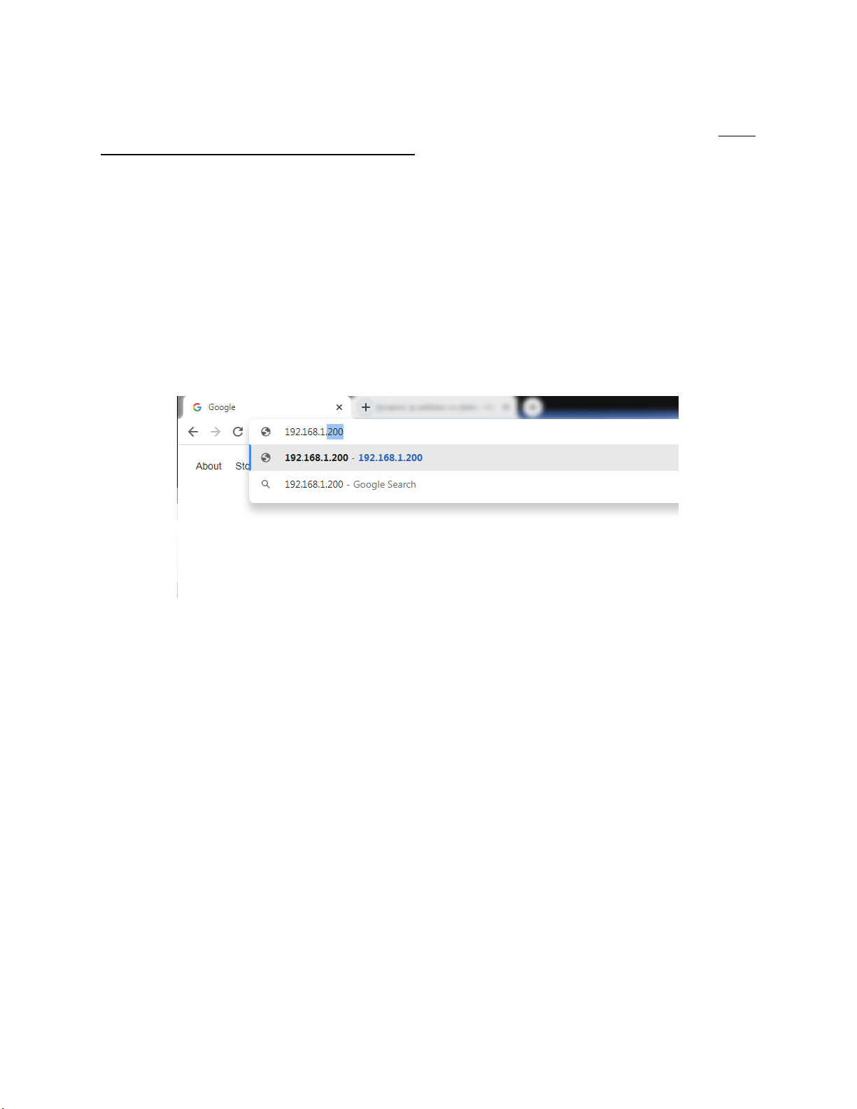
This section is intended for use by persons familiar with Ethernet network setup. The SGSM has
a static IP Address so that the web interface can be accessed easily. The default IP Address of
the sensor is 192.168.1.200.
If the default IP Address does not allow you to connect to this device through the web browser
(see Control Interface via Web Browser section), the IP Address of the sensor can be found by
using SSi’s
nLocateIP
software. This method is described in the following subsection.
nLocateIP Method
Once the unit is connected to the network, you should be able to locate it using SSi’s
nLocateIP
software. This program is available from SSi. To use it in locating the unit on the network, follow
these steps on a Windows-based PC:
1. Ensure that the unit is connected to the network.
2. Open the nLocateIP program
3. Once the program opens, click the Search button. The program will begin searching for SSi
devices connected to the network.
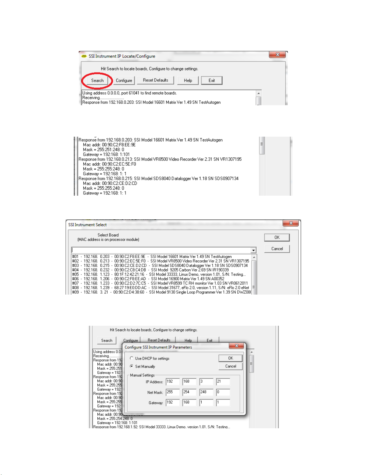
Single Gas Sensor Module (SGSM)
Operations Manual
Super Systems Inc.
Page 19 of 38
Page 19 of 51
4. Look for identifying text in the list of instruments. It includes the type of instrument and
serial number. It also provides the IP Address information for the sensor.
5. Click the Configure button and choose the sensor to change its IP Address settings.
6. Click on the device description to highlight it and click the OK button. This will display the
device’s IP settings, which can be changed to match the network to which it’s connected.
Single Gas Sensor Module (SGSM)
Operations Manual
Super Systems Inc.
Page 20 of 38
Page 20 of 51
The sensor’s IP Address settings will be changed immediately to allow it to communicate. If you
are unable to find the unit in the list of devices, it is possible that a network setting (such as
subnet mask) may be different, the unit may be connected to a different network, or the unit
may not be powered on. SSi recommends consulting an IT engineer or network administrator. If
needed, call SSi at (513) 772-0060.
Control Interface via Web Browser
The SGSM can be controlled using a web browser on your computer. The web browser connects
to the unit through an Ethernet connection. The computer you are using and the unit need to be
on the same network with the same subnet mask. Contact your IT administrator if you have
network setup questions.
Enter the IP Address into the search bar of the web browser.
Access Password:
Contact SSi at (513) 772-0060 for more information on the password used to
access secured options.
Note that the interface pages shown below are for the H2 option.
This manual suits for next models
2
Table of contents


