SSL Energie P-CHARGE User manual

Instruction Manual Updated 08/2016
Please keep these instructions for future reference.
Charging in the private sector

2
Instruction Manual Updated 08/2016
2 | 44
1. Introduction 4
2. Safety and legal information 4
2.1 Warning notication concept 4
2.2 Qualied electrical technician 5
2.3 Person instructed in electrics 5
2.4 Trademark protection 5
2.5 Disclaimer 6
2.6 Safety information 6
2.7 Intended use 7
3. Scope of delivery 8
3.1 Checklist packaging content 8
4. General 8
4.1 Overview and structure of the Wallbox 8
4.2 Control elements 8
4.3 Rating plate 9
4.4 Electrical components 9
4.4.1 Mounting the Wallbox carrier plate 9
4.4.2 Potential charging cables / charging sockets 9
4.4.3 Communication via EWS Box 10
4.4.3.1 Technical data 10
4.4.3.2 Terminal clamps and connections 10
4.5 Technical data Wallbox (independent of variant) 15
4.6 Technical data Wallbox (independent of equipment) 16
5. Installation 16
5.1 Required installation material 16
5.2 Preparing for the installation 17
5.2.21 Preparing the Wallbox 17
5.3 Preparing for the on-wall connection 17
5.4 Mounting the Wallbox 18
5.4.1 Installation of the Wallbox carrier plate 18
5.4.2 Electrical connection of the Wallbox 20
5.4.2.1 Residual current circuit breaker (RCCB) Type B 20
5.4.2.2 Circuit breaker 21
5.4.2.3 Cable specication connection line 22
5.4.3 Mounting the Wallbox housing 24
Charging in the private sector

Instruction Manual Updated 08/2016
3 | 44
6. Operational startup 25
6.1 Conguration of the EWS-Box 25
6.1.1 Conguration of the LAN-connection 25
6.1.2 Conguration via EWS-Firmware (HTML) 27
6.1.3 Details 27
6.1.4 Settings 27
6.1.5 Installation 28
7. Operation 34
7.1 Wallbox for private use 34
7.2 Wallbox in "optimized charging" mode 34
8. Maintenance 35
8.1 Service notes 35
8.2 Trouble-shooting 35
8.3 Links for support 37
9. Conformity 38
9.1 Corresponding guidelines and standards 38
9.2 Declaration of conformity 39
10. Disposal 40
11. Contact information 44

4
Instruction Manual Updated 08/2016
4 | 44
1. Introduction
Thank you for choosing a SSL Energie GmbH product. The P-CHARGE
Wallbox was specically designed for the charging of electric vehicles in the
private sector. A reliable charging infrastructure is available to you with a
variety of optional features and performance capabilities. The sustainable
mobility of tomorrow begins with the P-CHARGE Wallbox. The P-CHARGE
EWS-Box is the heart of system. This communication module undertakes all
control- and signaling functions required, in accordance with IEC 61851-1,
Mode 3, for the connection of an electric vehicle (EV) to an Electric Vehicle
Supply Equipment (EVSE). Parameters for a self-sucient or for a systems-
integrated operation can be congured via a web platform. Variants with
provision for optimized charging oer additional functionality. Working in
conjunction with the SmartPvCharge or another embedded system, the
electric vehicle can be charged using surplus PV energy only, if so required.
PLEASE NOTE
The P-CHARGE Wallbox is delivered pre-assembled and ready
for connection. Once connected to the supply grid, including
her fault current- and line protection with an energy meter if
required, the P-CHARGE Wallbox is ready for charging.
2. Safety and legal information
2.1 WARNING NOTIFICATION CONCEPT
This instruction manual contains guidelines for the protection of human
safety and for the prevention of material damage. These must be carefully
observed. Safety guidelines are marked with a warning triangle. The warning
triangle is not added to guidelines relating to the prevention of material
damage. The following warning symbols are added according to the specic
level of danger.
DANGER: indicates that failure to conform with the appropri-
ate safety measures will lead to death or to serious injury.

Instruction Manual Updated 08/2016
5 | 44
WARNING! indicates that failure to conform with the appro-
priate safety measures can lead to death or to serious injury.
PLEASE NOTE: indicates that failure to conform with the ap-
propriate safety measures can lead to minor personal injury.
PLEASE NOTE: indicates, with no symbol, that failure to
conform with the appropriate safety measures can lead to
material damage.
PLEASE NOTE: indicates that failure to conform with the cor-
responding guidelines can lead to an unwanted result or state.
If a situation presents several levels of danger, the warning notice is applied
at the highest level in each case. If a warning notice with warning triangle
serves to alert readers to the risk of personal injury then the warning may
also contain an additional warning against material damage.
2.2 QUALIFIED ELECTRICAL TECHNICIAN
The mounting and startup of the P-CHARGE Wallbox must be executed by a
qualied electrical technician and in full compliance with this documenta-
tion. According to DIN VDE 0105-100:2009-10 3.2.3 the term Qualied Electri-
cal Engineer/Technician refers to a person who, due to his/her specialist
training, knowledge and experience as well as familiarity with the current,
valid norms, has the capacity to assess the task assigned to him/her and is
able to recognize potential hazards.
2.3 PERSON INSTRUCTED IN ELECTRICS
The operation of the P-CHARGE Wallbox must be driven by a person who is
fully conversant with the electrics of the system and in full compliance with
this documentation. According to DIN VDE 0105-100:2009-10 3.2.4 the term
"person who is conversant with the electrics of the system" refers to a person
who, has received instruction from a qualied electrical technician relating
to tasks assigned to him/her, as well as to the potential hazards of non-
compliant behavior and who has learned about the safety equipment and
protective measures required.
2.4 TRADEMARK PROTECTION
P-CHARGE® is a registered trade mark of the company SSL Energie GmbH. The
remaining denotations in this manual may be trademarks, the use of which
by third parties for their own purpose may injure the rights of the proprietor.

6
Instruction Manual Updated 08/2016
6 | 44
2.5 DISCLAIMER
Although the contents in this instruction have been carefully prepared, SSL
Energie accepts no liability for the validity, accuracy, completeness or quality
of the published information. Data provided in the installation manual is
checked regularly for accuracy and is updated as required. Corrections are
included in subsequent versions of the document.
2.6 SAFETY INFORMATION
DANGER
Danger of electric voltage
A voltage-free state must be established prior to the start of
work at electric plants and at the P-CHARGE Wallbox in order
to avoid accidents resulting from contact with live parts.
Please note the 5 safety rules in accordance with DIN VDE
0105-100:2009-10 6.2.
WARNING!
Line- and personal protection
The safety device integrated into the P-CHARGE Wallbox
serves to protect the unit and is designed for use with this
device only. A separate line and personal protection device
must be installed on the customer side for each charging
point. To this end an RCD IΔn≤30mA (with 1-phase devices
an RCD with min. Type A and with 3-phase devices an RCD
with min. Type B) and a upstream circuit-breaker must be
active. The circuit breaker must present at least trip charac-
teristic B and should be laid to comply with the respective
Wallbox variant.
WARNING!
Danger of asphyxiation
Charging gassing batteries in an interior space can lead to
asphyxiation. According to the IEC 61851-1 the customer
installed ventilation system must be controllable via the
Wallbox. Monitoring of the customer-installed, mandatory
ventilation system cannot be performed by the P-CHARGE
Wallbox and its integrated P-CHARGE EWS-Box.

Instruction Manual Updated 08/2016
7 | 44
PLEASE NOTE
The selectivity of the building installation must be taken into
account when installing line protection and the residual cur-
rent device in the upstream power distribution.
WARNING!
Revocation of manufacturer's warranty due to impermissi-
ble changes to the device
Changes to the devices are not permitted. Non-conformance to
this regulation will result in revocation of manufacturer's warranty.
WARNING!
Damage to the communication module
Installation and maintenance operations in direct conjunction
with the P-CHARGE EWS-Box must always be carried out using
ESD equipment. Electrical discharging can damage internal
module components.
2.7 INTENDED USE
WARNING!
The tethered plug connection between the electric vehicle and
the P-CHARGE Wallbox must not be extended by introducing
an additional charging connector and coupler or by adding a
second charging cable.The use of adapter plugs to connect the
vehicle to the charging socket is also prohibited.
WARNING!
The P-CHARGE Wallbox may be utilized exclusively for purposes
outlined in the corresponding technical documentation. Fail-
safe operation of the P-CHARGE Wallbox is wholly dependent
upon the correct storage, assembly, mounting, installation,
startup, operation and maintenance of the device and, of
course, correct transportation. The corresponding guidelines in
the documentation must be observed.
8
Instruction Manual Updated 08/2016
8 | 44
3. Scope of delivery
3.1 CHECKLIST PACKAGING UNIT
At delivery please check the contents of the package to ensure all parts have
been included. The following items must be included in the delivery of the
P-CHARGE Wallbox.
• P-CHARGE Wallbox 1x
• Pan Head screws 6x50mm TX30 A2 4x
• Expansion plugs S8 grey 8x40mm 4x
• Sealing washer with EPDM coating 8.4x16 A2 4x
• Self-tapping screw TX 3,5 x 16 center with collar; Stainless steel black 2x
• Drilling template 1:1 1x
• Instruction manual 1x
• Schematic circuit diagram 1x
4. General
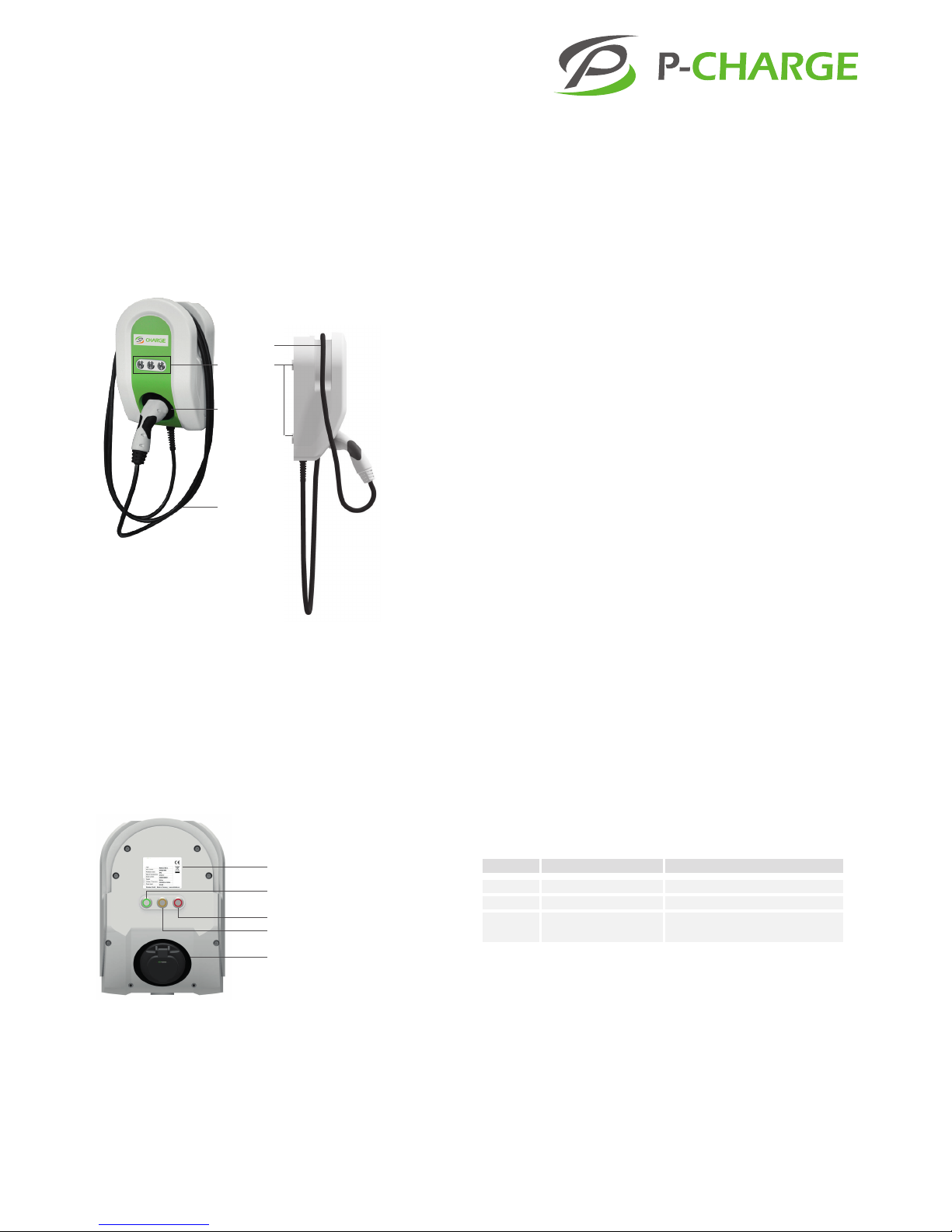
4.1 OVERVIEW AND STRUCTURE OF THE WALLBOX
Overview of components visible from the exterior of the P-CHARGE Wallbox
(Image 1)
4.2 CONTROL ELEMENTS
Explanation of individual control elements e.g. buttons on the Wallbox (Im-
age 2).
* "OPTIMIZED CHARGING":
By selecting the function "Optimized Charging", the charging process can
be controlled in accordance with predened parameters. When operating
in conjunction with SmartPvCharge or another embedded system, it is pos-
sible to charge electric vehicles using surplus PV energy only. Similarly, any
charging- or eet management system or indeed any other system can be
implemented via LAN or serial interface. SSL Energie is happy to make avail-
able the relevant protocol for such implementations.
Control elements
IEC 62196-2 charging cable
(this may vary with other variants)
Charging cable, length approx. 5m
Cable suspension
Mounting points
Rating plate
Button 1
Button 2
Button 3
Charging socket IEC 62196-2 Type 2
Image 1: Exterior view Wallbox
(Variant Wallbox with IEC 62196-2 Type2 charging cable)
1 This functionality is only possible with an active server operation
Picture 2: Control elements of the Wallbox
(Variant Wallbox with IEC 62196-2 Type2 charging socket)
Button Name Function
Button 1 Start button Start the charging process
Button 2 Stop button End the charging process
Button 3 Optimized charging1Start the charging process
"Optimized charging"*
Table 1: Explanation of control elements

Instruction Manual Updated 08/2016
9 | 44
4.3 RATING PLATE
The following information can be taken from the rating plate (Image 3). Ac-
cess the rating plate by removing the cover. Instructions on how to remove
the cover can be found in Chapter 5.2.1.
4.4 ELECTRICAL COMPONENTS
4.4.1 MOUNTING THE WALLBOX CARRIER PLATE
The following image presents an overview of the electro-technical com-
ponents implemented on the carrier plate. Access the carrier plate and its
components by removing the cover and opening the housing
(Image 4).
4.4.2 OPTIONAL CHARGING CABLES / CHARGING SOCKETS
The P-CHARGE Wallbox is available in a variety of designs. Choose between
charging cable Type 1, charging cable Type 2 and charging socket Type 2.
CHARGING CABLE IEC 621962 TYPE 1
• Charging current: up to 20A
• 4-pole: P+N+PE+CP
• Output power: up to 4.6 kW
CHARGING CABLE IEC 621962 TYPE 2
• Charging current: max. 32A
• 7-pole: 3P+N+PE+CP+PP
• Output power: up to 22 kW
CHARGING SOCKET IEC 621962 TYPE 2
• Charging current: max. 32A
• 7-pole: 3P+N+PE+CP+PP
• Output power: up to 22 kW
EWS Box
Fastening points plug-in card to housing rear panel
Cable laying
Cable in-wall entry
Charging contactor
Terminal clamps ventilation provided by customer
Main connection terminals
Device protection EWS (Microfuse, Rated current 6, 3A,
Rated voltage 250V, Glass tube fuse in accordance
with EN 60127-2-3)
Image 3: Rating plate
(variant specic Rating plate)
Picture 4: Electrical components - Example, technical changes reserved
electrical carrier plate Wallbox with charging cable IEC 62196-2 Type2
(up to 32A)
20500100259
EN61439-7
261020-504
261020-704
261020-804
261020-703
261020-803
20500100260
EN61439-7
261020-504
261020-704
261020-804
261020-703
261020-803
20500100261
EN61439-7
261020-504
261020-704
261020-804
261020-703
261020-803
20500100262
EN61439-7
261020-504
261020-704
261020-804
261020-703
261020-803
20500100263
EN61439-7
261020-504
261020-704
261020-804
261020-703
261020-803
20500100264
EN61439-7
261020-504
261020-704
261020-804
261020-703
261020-803
20500100265
EN61439-7
261020-504
261020-704
261020-804
261020-703
261020-803
20500100266
EN61439-7
261020-504
261020-704
261020-804
261020-703
261020-803

10
Instruction Manual Updated 08/2016
10 | 44
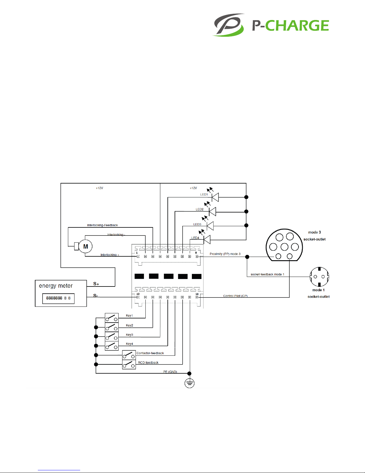
4.4.3 COMMUNICATION VIA EWS BOX
The communication between the P-CHARGE Wallbox and the electric vehicle
takes place via the integrated P-CHARGE EWS Box.
The EWS Box communication module undertakes all control- and signaling
functions necessary, in accordance with IEC 61851-1, Mode 3, for the con-
nection of an electric vehicle (EV) to an Electric Vehicle Supply Equipment
(EVSE). Parameters for a self-sucient or for a systems-integrated operation
can be congured via HTML pages.
4.4.3.1 TECHNICAL DATA
Nominal voltage 230 V
Nominal frequency 50 Hz
Power input 3.5 W (max.)
Locking actuator 2x 12V / 3A
Electrical power AC-15 2x300VA
Ambient temperature (during operation) -25 to 70°C
Relative air humidity < 93%
Overvoltage category II
Protection class IP20
Housing 6TE DIN Bearing rail 35mm
4.4.3.2 TERMINAL CLAMPS AND CONNECTIONS
Terminal connections and the connection diagram of the EWS Box are
shown below for incidental maintenance operations.
WARNING!
Cabling and wiring
Cabling and wiring within the P-CHARGE Wallbox must be car-
ried out exclusively by trained professional personnel.
WARNING!
Electrostatic discharge (ESD)
When working on the EWS-Box or on other electrical compo-
nents within the Wallbox, the appropriate ESD safety meas-
ures must be taken to avoid damage to electrical parts.

Instruction Manual Updated 08/2016
11 | 44
The most relevant terminal denotations are outlined once again and in more
detail in the following. Wires should be labeled to avoid erroneous recon-
nection following a required shutdown or In the event that plugs i.e. screw
terminals or jacks become loose at the EWS Box.
MAINS TERMINAL AND CONTACTOR TERMINAL
DANGER
Particular care and attention is needed when connecting wir-
ing to the mains terminals as this task exposes the engineer to
dangerous levels of voltage. For this reason, many installation
tasks at the mains terminals must be carried out exclusively by
qualied personnel and must be performed under voltage-
free conditions only. The standards must be observed in
accordance with DIN/VDE regulations.
X101 MAINS TERMINAL POWER SUPPLY TERMINAL: Connectivity to the
grid is eected across the mains terminal (L1/N/PE) for the EWS Box, for the
contactor circuits and for the ventilation circuitry.
X102 CONTACTOR TERMINAL: The wiring of contactor coils is eected via
the EWS Box. Care is to be taken that for each electric vehicle (EV), a nominal
charge of max. 300VA (AC-15) can be activated.The blower connection acti-
vates a contactor / relay which serves both electric vehicles in equal measure.
WARNING!
The connections in the X102 contactor terminal are designed
solely for the activation of charging contacters and/or blower
contacters and should never be used for the transmission of
power to an EV!
EV CONNECTION: The EWS Box generally has the capacity to provide an
independent supply of power to 2 electric vehicles (EV) simultaneously. EV
1 is connected to X401 and EV 2 to X402. The two connections are identical
for both EVs. In the P-CHARGE Wallbox the slot X401 is used for charging
control.
Grounding conductor (PE)
Neutral conductor (N)
Phase (L1)
Contactor fan/blower
Contactor EV2
Contactor EV1
Configuration bridges (Jumper)
Connection EV1
Mains terminal 230V AC (L1)
Contactor terminal
Interfaces RS232 / RJ45
15
Im nachfolgenden werden die relevantesten Klemmenbezeichnungen noch einmal genauer
erläutert. Im Falle eines nötigen Abschließens oder lösen von Steckverbindungen, in Form von
Schraubklemmen oder Steckverbindungen an der EWS-Box sind die entsprechenden Leitungen zu
beschriften, um einen fehlerhaften Wiederanschluss der Leitungen vorzubeugen.
Warnung
Elektrostatische Entladung (ESD)
Bei arbeiten an der EWS-Box oder anderen elektrischen Bauteilen in der
Wallbox Mono sind entsprechende ESD-Sicherheitsmaßnahmen zu
treffen um eine Beschädigung elektrischer Bauteile vorzubeugen.
Konfigurationsbrücken (Jumper)
Anschluss EF1
Netz-Klemme 230V AC (L1)
Schütz-Klemme
Schnittstellen RS232/ RJ45
17
Anschluss EF
Die EWS-Box ist grundsätzlich in der Lage, 2
Elektrofahrzeuge (EF) unabhängig voneinander
zu versorgen. Dabei wird EF 1 über X401 und
EF 2 über X402 angeschlossen. Die
Anschlüsse für beide EF sind identisch.
In der P-CHARGE Wallbox Mono wird der
Steckerplatz X401 für die Ladesteuerung des
EF verwendet.
Anschlussplan für eine Steckerleiste (X401):
(Für den Anschluss X402 ist der Anschlussplan für die Steckerleiste analog)
Im Anschlussplan sind alle Stecker Verbindungen dargestellt. Nachfolgende Tabelle erläutert die
belegten Steckplätze an der Steckerleiste. Das Anschlussschema variiert dabei nach der Variante
der P-CHARGE Wallbox Mono.
PIN-Nr.
Funktion - Anschlussstelle
Kabelfarbe
Verwendung in folgenden Art.-Nr.:
1
Verriegelung +
Rot
261020-701
261020-703
261020-801
261020-803
2
Verriegelung -
Schwarz
3
Verriegelungsrückmeldung
Blau
X102 X101
12
Instruction Manual Updated 08/2016
12 | 44
CONNECTION DIAGRAM FOR A POWER DISTRIBUTION UNIT X401:
(The connection diagram for the power distribution unit is identical for the
X402 slot). All plug connections are shown in the connection diagram. The
following table denes the occupied slots on the power distribution unit. The
connection diagram varies according to P-CHARGE Wallbox variant.
Sample picture, Circuit diagram
Instruction Manual Updated 08/2016
13 | 44
PIN
no.
Function - Connection point Cable
color
Utilization with
following item
no.s.:
1Locking device + red 261020-703
261020-8032Locking device - black
3Locking response blue
4+12V red All
5LED1 grey All
6LED2 pink All
7LED3 light blue All
8LED4 not assigned
9Proximity (PP) white All
10 Active energy meter S0- not assigned
11 Button 1 green All
12 Button 2 brown All
13 Button 3 black All
14 Button 4 not assigned
15 Charging contactor response orange All
16 RCCB response not assigned
17 PE (GND) dark blue All
18 Control Pilot (CP) red All
COMMUNICATION INTERFACES: The integrated communication interfaces
facilitate the control of access authorization, the local management of
conguration settings and the integration of the module into an existing
management system. The wires must have compatible contact plugs, each
with a retaining clip to prevent unintentional detachment of the connection.
The wires must not protrude from the sides of the clamps.
X201 PC CONFIGURATION: This connection allows for the entry of system-
relevant settings and for the transmission of permanent status queries.
X901 ETHERNET: The internet connection supports data transfer as per
10/100BASE-T and is allocated a MAC Address prior to transmission. The IP
address is preset (192.168.0.1) and can be changed via the conguration
settings (no DHCP).
RS 232
Ethernet
X901
X201 X202

14
Instruction Manual Updated 08/2016
14 | 44
CONFIGURATION VIA CONFIGURATION SWITCH JUMPER:
The communication module has a number of switches which can be con-
gured by the user to limit the maximal charging power, to reset an IP or to
change the PC-COM on the communication interface X201. Jumpers must
be set prior to startup of the module in order to be recognized. The module
can be be assigned a specic output capacity prior to startup and can there-
fore be deployed in any number of predened areas. Pins carrying a higher
voltage are removed prior to outbound delivery to comply with the prede-
ned maximal output, so as to avoid conguration errors on the part of the
customer which could result in damage to a vehicle at the charging point.
CHARGING CURRENT: A specic output capacity can be allocated to the
EWS Box. This can be eected using the jumper, which must be connected at
start-up of the module in order for the hardware to be recognized.
IPRESET: On removal of the jumper during operation, the current IP address
resets to the default conguration: 192.168.0.1.
PCCOM Connection of the jumper forces local administration across the PC
interface X201. Software updates can be implemented on the EWS Box using
this procedure.
WARNING!
The communication module is not able to balance the
current-carrying capacity against the congured bridge. The
user must therefore ensure that the system is able to full
all necessary prerequisites. The task of the mode bridge is to
compare the capacity of a connected cable with the potential
of the respective system.
IP reset
PC-COM
Charging current 20A
Charging current 32A
Charging current 63A
Charging current 13A

Instruction Manual Updated 08/2016
15 | 44
4.5 TECHNICAL DATA WALLBOX INDEPENDENT OF THE VARIANT
COLOR SCHEMES
• Body RAL 9003
• Front RAL 9003 and RAL 6018
• Custom color schemes on request
DIMENSIONS / WEIGHT
• W/H/ D: approx. 278x403x171 mm (without charging cable and plug)
• Depth with charging cable: approx. 236 mm
• Weight (variant specic): approx. 4.8 kg (min.), approx. 7.2 kg (max.)
INSTALLATION AND ASSEMBLY
• Wall mounting
• Recommended installation height: approx. 1250 mm
• On-wall and in-wall cable routing
- On-wall from above
- In-wall from rear
• Suitable for interior and exterior locations
• Terminal clamps: max. diameter 5x6mm² (Cu)
ELECTROTECHNICAL DATA
• Nominal power congurable: 6A, 10A, 13A, 16A, 20A, 25A, 32A
• Mains frequency: 50Hz
• Nominal voltage: 230/400V AC
• Terminal clamps: 6mm² (L1,L2,L3,N and PE)
• Protection class: IP54
• Overvoltage category: III
• Impact resistance: IK10
• Possible integration of customer-installed ventilation system
• Fault current and surge protection (customer side)
• Charging mode in accordance with IEC 61851-1 (Mode 3)
• Ethernet connection (RJ45)
• Operating status via LED in the buttons
ENVIRONMENTAL CONDITIONS
• Operational temperature: -25°C to +65°C
• Ambient air pressure: 860hPa to 1060hPa
• Ambient air humidity: 5% to 95%
16
Instruction Manual Updated 08/2016
16 | 44
4.6 TECHNICAL DATA WALLBOX INDEPENDENT OF THE EQUIPMENT
5. Installation
5.1 REQUIRED INSTALLATION MATERIAL
We recommend that you use the following tools to ensure a correct and
compliant installation of the Wallbox:
• Screwdriver TX 30
• Screwdriver TX 25 (at least 10cm length)
• Screwdriver TX 20
Item no.
261020-504 x
Charging capacity up to 4.6 kW
Charging current up to 32A
Charging capacity up to 22 kW
x
Charging current up to 20A
Charging capacity up to 13.9 kW
Item no.
261020-704
261020-804
Item no.
261020-703
261020-803
Charging capacity up to 4.6 kWCharging capacity up to 4.6 kW
x
Charging current up to 32A
x
Charging current up to 32A
x
Charging capacity up to 22 kW
x
Charging capacity up to 22 kW
x
Charging current up to 20A
x
Charging current up to 20A
x
Charging capacity up to 13.9 kW
x
Charging capacity up to 13.9 kW
Instruction Manual Updated 08/2016
17 | 44
5.2 PREPARING FOR THE INSTALLATION
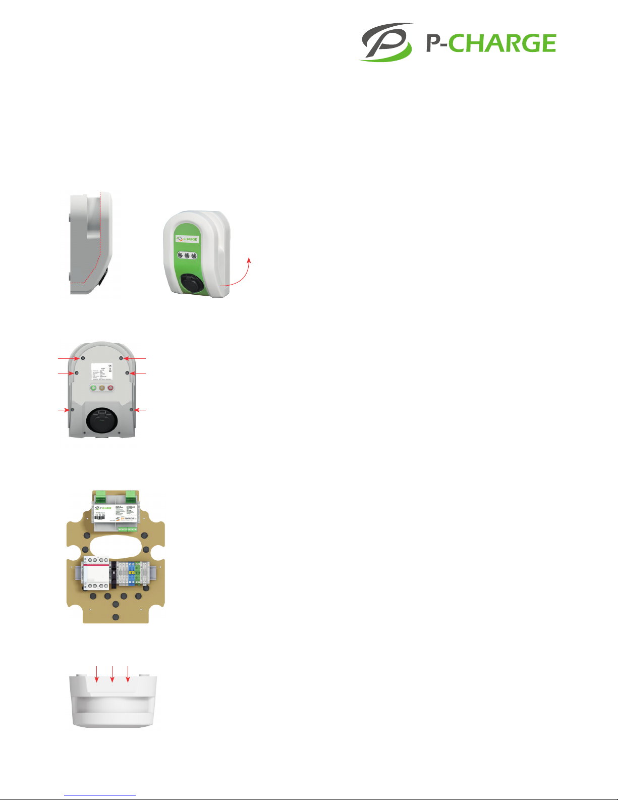
5.2.1 PREPARING THE WALLBOX
Please start by removing the Wallbox cover. The Wallbox cover to be
removed is outlined in Image 5 with a red dotted line. To do this take hold
of the cover at the underside of the Wallbox and pull forward and upwards,
see Image 5. The front panel can be pulled away from the underside of the
Wallbox where it is xed closed with two plastic catches. Once released, the
housing cover can now be lifted upwards and away (see Image 6).
In the next step remove the 6 x screws which connect the body of the Wall-
box to the carrier plate. Use a TX25 screwdriver (min. length 10cm). Position-
ing of the screws is demonstrated in Image 7.
The Wallbox body can now be removed by pulling it towards you.
5.3 PREPARING FOR THE ONWALL CONNECTION
Insofar as the electric supply line and/or the data line/s are surface mounted
and routed into the Wallbox the Wallbox carrier plate must make provision
for this. Lines enter the device at the top side of the Wallbox. There are three
possible entry points into the carrier plate, which, itself, is xed at its middle
points via a small central hole.
In each case, please ensure that the protection class IP54 (protection on all sides
against spray water and dust in damaging quantities) is safeguarded following
mounting of the cable glands. Cable glands must be mounted as follows.
PROCEDURE FOR CREATING LINE ENTRYPOINTS
1. Dene the position and number of entry-points.
2. Determine size of glands (M16, M20, M25 or M32)
3. Remove the carrier plate with the electric wiring. Using a TX 20 screw-
driver loosen the 6 fastening screws which serve to connect the carrier
plate to the housing rear panel, see Image 8.
4. Pre-drill aperture using a twist drill.
5. Create the entry-point (max. M32 centrally and M25 left and right)
using a step drill.
6. Mount the desired glands (M16, M20, M25 or M32).
7. Now rejoin the base plate to the carrier plate by tightening the 3
screws loosened in step 3.
Picture 5: Removal of
facing 1
Picture 6: Removal of
facing 2
Image 9: Overview of position of
designated on-wall entry points
Image 8: Position of carrier plate and
mounting rack - Example, technical
changes reserved
Picture 7: Position of the
housing screws

18
Instruction Manual Updated 08/2016
18 | 44
5.4 MOUNTING THE WALLBOX
Please determine the optimal location and position for the P-CHARGE Wall-
box prior to mounting. Ensure you take the measurements of the Wallbox
into account!
Height H 403mm
Width W 278mm
Depth with charging socket D1171mm
Depth with charging cable D2236mm
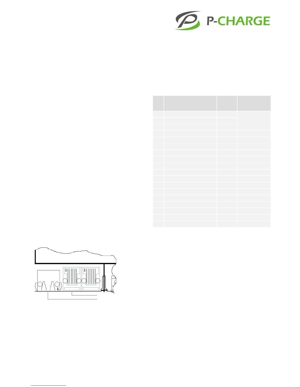
Mandatory height of centre of charging point c1250 mm above nished
oor. See Image 13 (P-CHARGE Wallbox 261020-704, similarly other variants).
The exact position of supply lines with in-wall installations can be taken from
Image 14 or from the drilling template included in delivery. The Wallbox
should be mounted in a place and position which allows for optimal acces-
sibility by the user. Please observe the standard cable length (approx. 5m) of
the P-CHARGE Wallbox (EVSE) and the position of the charging bush on the
electric vehicle (EV).
5.4.1 MOUNTING THE WALLBOX CARRIER PLATE
1. Align the drilling template perpendicular to the desired position and secure.
2. Mark the position of drill holes and remove the drilling template. Next
drill holes - diameter 8mm. According to the screw anchor manufac-
turer the boreholes should be drilled to a depth of at least 55mm.
3. Laying supply lines
a) On-wall: Feed supply lines into the glands
(only once rear wall has been mounted should the glands be secured)
b) In-wall: Feed supply lines through the rear wall.
The lines must be fed through correctly at the required membrane spouts.
4. Secure the carrier plate of the Wallbox to the wall using pan head
screws 6x50mm and sealing washers, tightening at TX20 A2 as is
appropriate for the masonry.
5. Connect customer supply line to the designated main connection
terminal X1.
Picture 10: Wallbox dimensions,
front view
H
W
278mm
403mm
1250mm
D2
Picture 12: Wallbox dimensions,
front view charging cable
Image 13: Installation height
Picture 11: Wallbox dimensions,
front view charging socket
D1

Instruction Manual Updated 08/2016
19 | 44
WARNING!
Such work must be carried out exclusively by qualied electri-
cal technicians! A faulty neutral conductor can cause irrevoca-
ble damage to the device. Ensure appropriate dimensioning
of the connection line. Dimensioning of the connection line
is subject to installation type, line length, charging capacity
(of Wallbox) etc. and can therefore not be predened as a
standard. The connection line must be secured well enough to
ensure it does not come loose from the terminal clamps. The
connection line length must be short enough to avoid poten-
tial contact with other live connections but long enough to
incorporate the necessary safety devices.
6. A LAN connection can be established at the Ethernet port (X301) of the
EWS-Box as an option. In the same way the ventilation of the building
can also be connected to the EWS Box at the terminal clamp X3 (see
schematic circuit diagram).
WARNING!
The connections in the X102 contactor terminal are designed
solely for the activation of charging contacters and/or blower
contacters and should never be used for the transmission of
power to an EV!
7. Ensure that the supply lines are strain-relieved and that the insulation
standards are adhered to. Additional fastening points are available to
facilitate the running of lines through the Wallbox (via cable retainer).
4x fastening points for wall mounting
Bushing - data cable
Bushing - power supply cable
Controller for customer-installed ventilation system
Picture 14: P-CHARGE Wallbox drilling template

20
Instruction Manual Updated 08/2016
20 | 44
5.4.2 ELECTRICAL CONNECTION OF THE WALLBOX
The electrical connection of the Wallbox must comply with a number of
specications, depending upon the variant and its respective connection
capacity.
PLEASE NOTE
The following electrical installation data is oered by the
company SSL Energie in the form of recommendation. The
data must be supplemented or if necessary even reworked to
correspond with respective country regulations and norms.
PLEASE NOTE
The technical connection conditions of the respective network
operators are to be observed with regard to unbalanced load.
8. Loosely tighten the 6 fastening screws M5x20 using a TX25 screwdriver,
see gure 7.
9. Align the housing once more and check its correct position; safeguard
that the seal faces have sucient contact.
10. Now tighten the 6 screws fully.
11. All that now remains to complete the installation, is to replace the front
housing of the Wallbox. Fit the tongue at the upper side of the housing
cover into the corresponding groove in the Wallbox housing and push
the housing cover at the lower end of the Wallbox to the back.
12. Your Wallbox is now fully installed and can be used to charge electric
vehicles.
5.4.2.1 RESIDUAL CURRENT CIRCUIT BREAKER RCCB TYPE B
If the load characteristic relating to potential DC residual currents > 6mA
is not known then measures must be taken to assure protection in the
event of residual current, e.g. through deployment of an RCD Type B, c.f.
DIN VDE 0100-722 (VDE 0100-722):2012-10. To this end we recommend
the implementation of a so-called "AC/DC" sensitive residual current circuit
breaker (RCCB). This "Type B RCCB" is not included with the Wallbox and
must be incorporated in the upstream house installation. SSL Energie hereby
recommends the implementation of RCCB Type B ABB F204 B+40/0,03 or a
comparable element.
Table of contents


