SSP CAM/TZ YG-LED318 User manual
USER MANUAL
YG-LED318
CAM/TZCAM/TZ

3.6--DMX512 SETTINGS....................................................................10.
PART 4 USING A DMX512 CONTROLLER....................................15.
4.1--BASIC ADDRESSING.................................................................15.
4.21--CHANNEL ASSIGNMENT .......................................................15.
4.31--BASIC INSTRUCTIONS FOR DMX512 OPERATION .................23.
PART 3 DISPLAY PANEL OPERATION.........................................6.
3.1--BASIC..........................................................................................6.
3.2--MENU..........................................................................................7.
3.4--ACTIVATING AUTO PROGRAMS.................................................10.
3.7--PERSONALITY...........................................................................11.
3.8--ID ADDRESS..............................................................................11.
3.10--SPECIAL SETTINGS.................................................................12.
3.13--A CTIVATE THE PASSWORD .................................................... 14.
3.9--EDITING CUSTOM PROGRAMS ................................................ 12.
3.12--RGB CALBRATION .................................................................. 14.
PART 1 PRODUCT (GENERAL)....................................................1.
1.1--TECHNICAL SPECIFICATIONS.....................................................1.
1.2--SAFETY WARNING......................................................................2.
PART 2 INSTALLATION...............................................................3.
2.1--MOUNTING...................................................................................3.
2.3--SETTING UP WITH A DMX512 CONTROLLER.................................3.
2.3-1--DMX512 ADDRESSING WITHOUT ID ADDRESSING......................................4.
2.3-2--DMX512 ADDRESSING WITH ID ADDRESS..................................................4.
2.2--POWER CONNECTION..................................................................3.
3.3--EDIT STATIC COLOUR.................................................................9.
PART 5 APPENDIX......................................................................25.
5.1--MAINTENANCE......................................................................... 25.
3.5--RUN MODE................................................................................ 10.
3.11--WHITES SETTING ....................................................................13.
ABLE OF CONTENTS
T
25
4.22--CHANNEL ASSIGNMENT .......................................................20.
4.32--BASIC INSTRUCTIONS FOR DMX512 OPERATION .................24.
5.1 MAINTENANCE
1
2
3
4
5
6
7
8
9
10
Front cover
Rubber seal
Clear glass
Lens completed set
LED PCB
Heat sink
Power supply
Power connection board
Display PCB
Driver PCB
Casing
Adjusting stainless steelknob
No ITEM
Display clear plate
Button seal
11
12
13
14
15
16
17
18
No ITEM
1
2
3
4
56
78
9
10
11 12 13
14
15
16
17
18
±ÈÀý25.400
Main support
Secondary support
Power cable socket
DMX cable socket
5 APPENDIX
1PRODUCT (GENERAL)
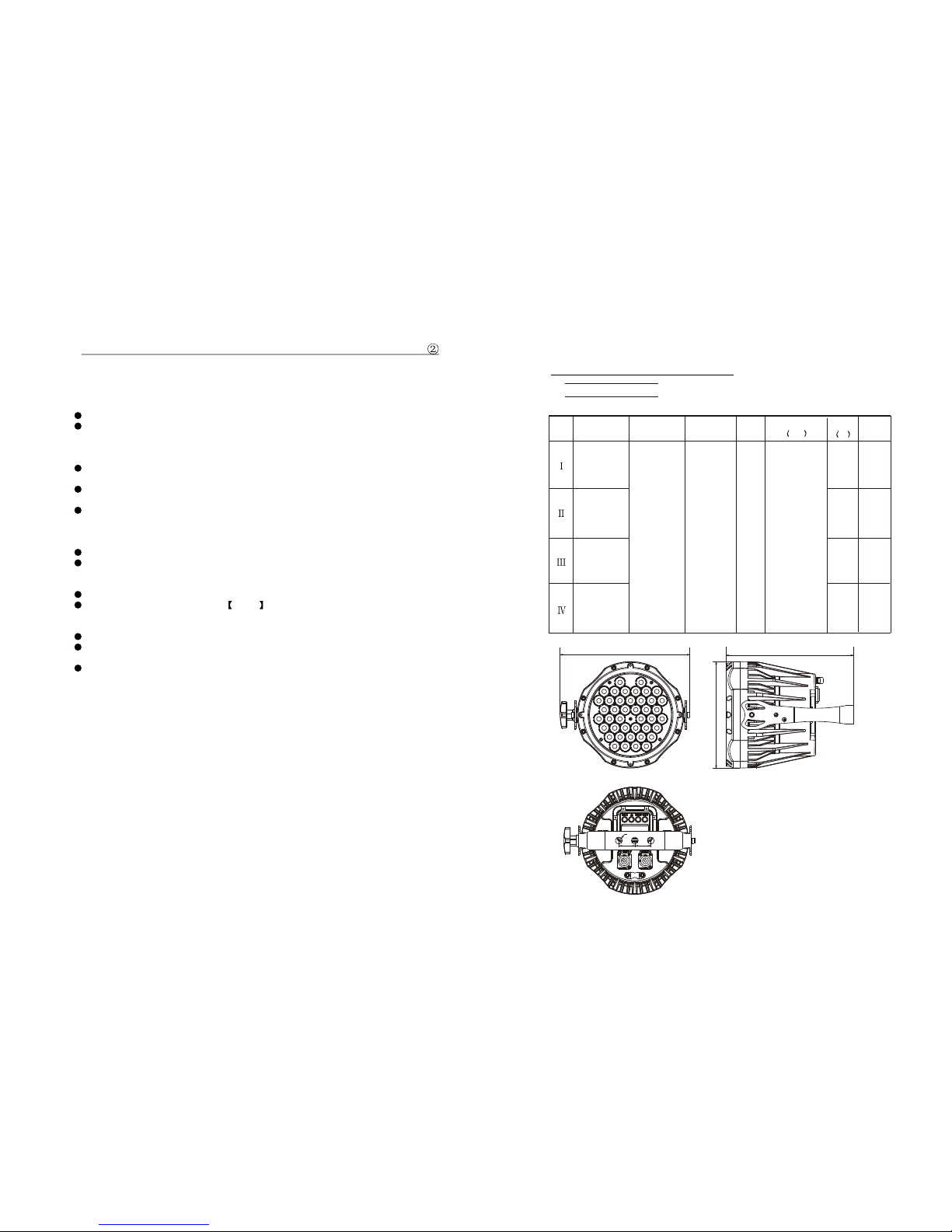
1.1 TECHNICAL SPECIFICATIONS
LED MODULE
24 1
Model Voltage Operation
Temperature
Weight
Dimensions 2
mm
Power
W
IP
AC100~240V
50/60Hz -20~45 4.8 245x205x245
CW:1Wx24
WW:1Wx18
R:1Wx12
G:1Wx12
B:1Wx12
W:1Wx6
CW:1Wx24
WW:1Wx18 IP67
R:1Wx12
G:1Wx12
B:1Wx12
W:1Wx6
IP67
70
245mm
205mm
245mm
30mm
13mm
30mm
Type
4.32 BASIC INSTRUCTIONS FOR DMX512 OPERATION (STD.2)
MASTER DIMMER
CH1 controls theintensity of thecurrently projected color
When the slideris at thehighest position (255)the intensity ofthe output is
the maximum
COOL WHITE & WARM WHITE SELECTION
CH2 and CH3 control the intensityratio of eachof the WARM WHITE &
COOL WHITE LEDs.
When the slideris at thehighest position (255)the intensity ofthe color is
the maximum.
CH2 and CH3 can be combinedtogether to createwhites with different
color temperature.
STROBE
CH 5 controlsthe strobe ofCH1 to CH4
CH5 has priorityover CH2, CH3& Ch4.
WHITE MACRO
Ch4 allow userto select 5 whites with different color temperature.
The 5 whites are took from the CAL1 on Display panel.
ID ADDRESS SELECTION
Ch6 is usedto select thetarget ID address.
Each independent DMXaddress may haveupto 66 independentID
addresses.
An IDaddress of 0will activate allID address locations.
APPLY:(LED318WW/LED318WWT)
70
50
50
1.2 SAFETY WARNING
IMPORTANT
ALWAYS READ THE USER MANUAL BEFORE OPERATION.
PLEASE CONFIRM THAT THE POWER SUPPLY STATED ON THE
PRODUCT IS THE SAME AS THE MAINS POWER SUPPLY IN YOUR
AREA.
This product must be installed by a qualified professional.
Always operatethe equipment asdescribed in theuser manual.
A minimum distance of 0.5m must be maintained between the
equipment and combustible surface.
The product must always be placed in a well ventilated area.
Always make sure that the equipment is installed securely.
DO NOT stand close to the equipment and stare directly into the LED
light source.
Always disconnect the power supply before attempting and
maintenance.
Always make sure that the supporting structure is solid and can
support the combinedweight of theproducts.
The earth wire must always be connected to the ground.
Do not touchthe power cablesif your handsare wet.
ATTENTION
This product left the place of manufacture in perfect condition. In
order to maintainthis condition andfor safe operation, the user must
always follow theinstructions and safety warnings described in this
user manual.
Avoid shaking or strong impacts to any part of theequipment.
Make sure thatall parts ofthe equipment arekept clean and free of
dust.
Always makesure that thepower connections are connected correct
and secure.
If there isany malfunction ofthe equipment, contact your distributor
immediately.
When transferring theproduct, it isadvisable to use the original
packaging in whichthe product left the factory.
Shields, lenses orultraviolet screens shall be changed if they have
become damaged tosuch an extentthat their effectiveness is
impaired.
The lamp (LED) shall be changed if it has become damagedor
thermally deformed.
223
4.31 BASIC INSTRUCTIONS FOR DMX512 OPERATION (TOUR)
MASTER DIMMER
CH1 controls theintensity of thecurrently projected color
When the slideris at thehighest position (255)the intensity ofthe output isthe
maximum
RED, GREEN & BLUE & WHITE COLOR SELECTION
CH2, CH3 &CH4 & CH5control the intensityratio of eachof the RED,GREEN,
BLUE & WHITE LEDs.
When the slideris at thehighest position (255)the intensity ofthe color isthe
maximum.
CH2, CH3, CH4& CH5 canbe combined togetherto create over16 million colors.
COLOR MACROS
CH6 selects therequired COLOR MACRO
CH6 has priorityover CH2, CH3, CH4 & CH5
CH1 is usedto control theintensity of theCOLOR MACRO
STROBE
CH 7 controlsthe strobe ofCH1 to Ch6
ID ADDRESS SELECTION
Ch11 is used to select the target ID address.
Each independent DMXaddress may haveupto 66 independentID addresses.
An IDaddress of 0will activate allID address locations.
AUTO
CH8 selects thepreset AUTO programsAT.01-AT.10 or thecustom AUTO
programs CUS.01-CUS.10
When activating thecustom AUTO programs CUS.01to CUS.10 thenit is possible
to control the STEP TIME and FADETIME using CH2 and CH3 respectively.
CH8 has priorityover CH2, CH3,CH4, CH5, CH6& CH7.
DIMMER SPEED
CH10 is for selecting the dimmer mode and dimmerspeed. When DIMMERis set
to Off , then RGBW and MASTER DIMMER are linear. The Dim 1/2/3/4 are
different speed of the nonlinear dimmer .
APPLY:(LED318XW/LED318XWT)
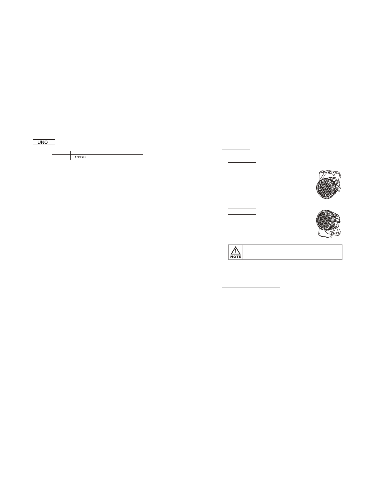
2.1 MOUNTING
HANGING
UPRIGHT
The fixture can be mounted in an
upright or sitting position using the
supporting brackets.
The fixture can be mounted in a
hanging position using the supporting
bracket. The bracket should be
secured to the mounting truss or
structure using a standard mounting
clamp. Please note that when hanging
the unit a safety cable should also be
used.
@ 220V: 24 units may be connected in series
@120V: 12 units may be connected in series
The LED MODULE can be mounted at any angle and in any
position. It is possible to further adjust the angle of the LED
MODULE using the two adjustment knobs located on the side of
the fixture.
2.2 POWER CONNECTIONS
Note:
If the signal cable is over 60m between the DMX512 controller and fixture
or beween twofixtures, then aDMX signal amplifieris needed aswell.
2 INSTALLATION
22 3
STATIC SETTING FROM DISPLAY MENU
1
CHANNEL FUNCTIONVALUE

421
2.3 SETTING UP WITH A DMX512 CONTROLLER
2.3-1 DMX512 ADDRESSING WITHOUT ID ADDRESSING
(TOUR MODE)
The figure above shows a simple DMX512
layout with the starting address of the first
unit set at 1, with the second set at 11and
so on... (Note that when used in this way,
the Ch10 ID function must be inactive (CH10=0))
DMX512
CONTROLLER
Connect the DMX512 controller to the units in series.
Each unit has 10 DMX channels so the DMX Addresses should increase by
increments of 10 (e.g. 1,11,21,31...)
The ID address has not been set so therefore when using the controller CH
10 must be inactive ( CH10=0 ).
It is also possible to deactivate ID address selecting ID OFF from the
Settings menu. on the fixture
Each DMX Address may be used as many times as required.
Any DMX address in the range from 001 to 512 may be used.
2.3-2 DMX512 ADDRESSING WITH ID ADDRESS
(TOUR MODE)
Connect the DMX512 controller to the units in series
Each unit has 10 DMX channels so the DMX Addresses should increase by
increments of 10 (e.g. 1,11,21,31...)
Each DMX Address may be used as many times as required.
Any DMX address in the range from 001 to 512 may be used.
Each DMX address may carry up to 66 separate ID addresses.
ID should be set in the menu on each unit in ascending values
(i.e. 1,2,3...)
ID On should be set in the Settings menu on each unit.
ID addresses are accessible from Ch10 on the DMX512 controller.
Example:
............
DMX Addr.1 DMX Addr.11 DMX Addr.21
ID ADDRESS
ID1~ID66
ID1
ID2
ID3
ID4
ID5
ID6
ID7
ID8
0 9
10 19
20 29
30 39
40 49
50 59
60 69
70 79
80 89
1~20Hz
STROBE
5
NO FUNCTION
WARM WHITE
COOL WHITE
CHANNEL FUNCTIONVALUE
6
WHITE MACROS
0 9 NO FUNCTION
ID11
ID12
ID13
110 119
120 129
130 139
ID14
ID15
140 149
150 159
ID21210
ID66255
ID20
200 209
ID18
ID16
ID17
160 169
170 179
180 189
ID19190 199
ID9
ID10
90 99
100 109
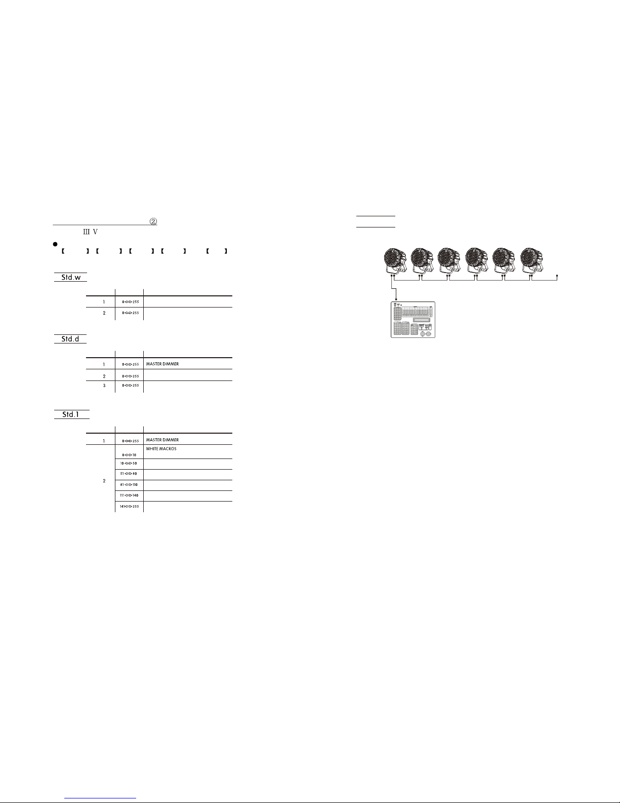
20 5
DMX512
CONTROLLER
Example:
The figure aboveshows a simpleDMX layout
which has usedthree units ateach DMX address.
The three unitshave different IDaddresses which
allows the userto collectively controlthe whole
group of unitsat that DMXaddress by setting
CH10 to 0,or to controleach unit independently by
first selecting theDMX address andthen by using
Ch10 to locatethe target IDaddress.
............
DMX Addr.1
ID Addr.1
DMX Addr.1
ID Addr.2
DMX Addr.1
ID Addr.3
DMX Addr.12
ID Addr.1
DMX Addr.12
ID Addr.2
DMX Addr.12
ID Addr.3
Note: This product have threeDMX512 channel configuration:
STD.W , STD.D , STD.1 , STD.2 and UNO
4.22 CHANNEL ASSIGNMENT
WARM WHITE
COOL WHITE
WARM WHITE
COOL WHITE
CHANNEL FUNCTION
VALUE
CHANNEL FUNCTION
VALUE
CHANNEL FUNCTIONVALUE
NO FUNCTION
STUDIO WHITE1:3200K
STUDIO WHITE2:3400K
STUDIO WHITE3:4500K
STUDIO WHITE4:4900K
STUDIO WHITE5:5600K
APPLY:( / )

619
3.1 BASIC
3 DISPLAY PANEL OPERATION
ENTER UP DOWN
MENU
enter the currentlyselected menu orconfirm the currentfunction value
scroll 'UP' through the menu listor increase the value of thecurrent function
scroll 'DOWN' through the menu list or decrease the value of the current function
scroll through themain menu orreturn to themain menu
MENU
ENTER
Ar2.s
1
2
0 255
CHANNEL FUNCTIONVALUE
3
0 255
0 255
HSV
1
2
0 255
CHANNEL FUNCTIONVALUE
3
0 255
0 255 VALUE(0~100%)
SATURATION(0~100%)
HUE(0~100%)
4
5
6
0
0
0
255
255
255
BLUE
GREEN
RED
WHITE
MASTER DIMMER
STROBE
18 7
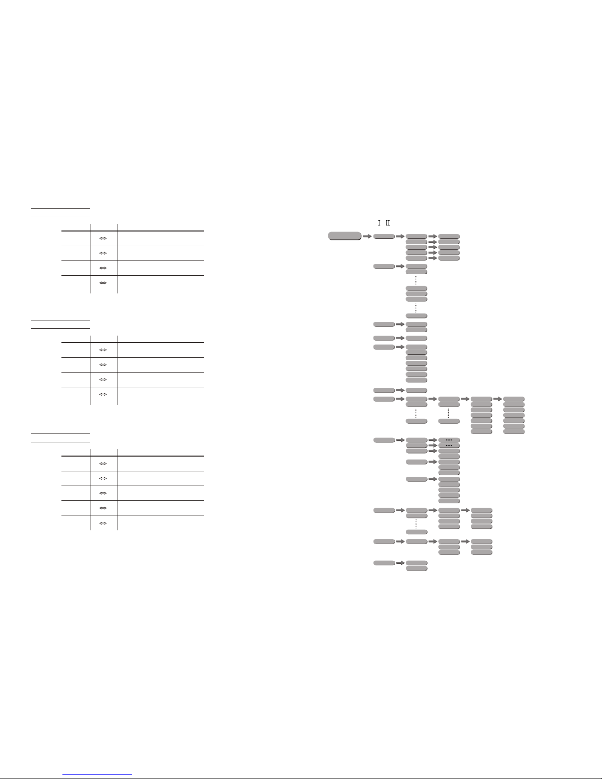
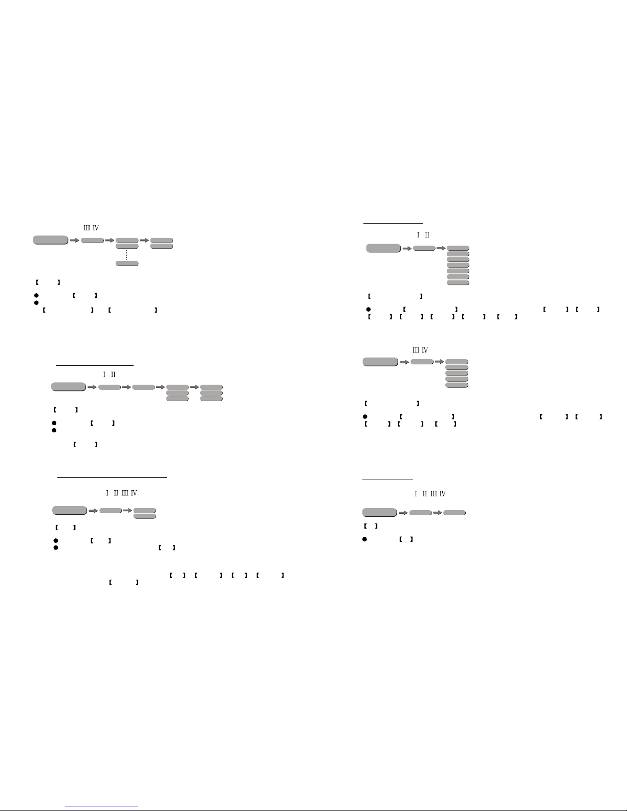
3.2 MENU
PR.01
PR.02
PR.10
RUN DMX
SLAV
SC.01
SC.02
SC.30
AT.01
AT.02
AT.10
AUTO
PR.01
PR.02
PR.10
D(001~512)
DMX
ID
ID(01~66)
Red
Green
Blue
White
Strobe
Time
Fade
(0~255)
(0~255)
(0~255)
(0~255)
(0~20)
(0~255)
(0~255)
TOUR
Arc.1
Arc.2
Ar1.d
Ar2.s
Ar2.d
MENU Red
Green
Blue
White
(0~255)
(0~255)
(0~255)
(0~255)
Strob (0~20)
STAT
PERS
EDIT
HSV
KEY ON
OFF
WT01
WT02
WT11
Red
Green
Blue
White
(0~255)
(0~255)
(0~255)
(0~255)
CAL1
RGBW Red
Green
Blue
(0~255)
(0~255)
(0~255)
CAL2
SET UPLD
ID ON
OFF
REST
RGBW
COLOR
Dim1
Dim3
Dim2
Dim4
Dim
UC
OFF
Off
APPLY:(Type- / )
Ar1.d
BLUE
1
2
0 255
CHANNEL FUNCTIONVALUE
3
4
0 255
0 255
0 255
GREEN
RED
MASTER DIMMER
Arc.2
BLUE
1
2
0 255
CHANNEL FUNCTIONVALUE
3
4
0 255
0 255
0 255
GREEN
RED
WHITE
Ar2.d
BLUE
1
2
0 255
CHANNEL FUNCTIONVALUE
3
4
0 255
0 255
0 255
GREEN
RED
WHITE
50 255
MASTER DIMMER

817
RUN dMX
SLAV
d(001~512)
DMX
ID
ID(01~66)
SET UPLd
Id ON
OFF
STd.d
STd.2
STd.1
MENU W(0~255)
C(0~255)
ST(0~20)
STAT
PERS
REST
STd.w
KEY ON
OFF
WT01
WT02
WT05
CAL1
dIM1
dIM3
dIM2
dIM4
dIM
OFF
W(0~255)
C(0~255)
UNO
ID21
ID22
210
211
11
ID20
200 209
ID19
190 199
ID18
180 189
ID14
ID15
ID16
ID17
140 149
150 159
160 169
170 179
ID65
ID66
254
255
ID8
ID9
ID10
ID11
ID12
ID13
80 89
90 99
100 109
110 119
120 129
130 139
CHANNEL FUNCTIONVALUE
ID6
ID7
60 69
70 79
Arc.1
BLUE
1
2
0 255
CHANNEL FUNCTIONVALUE
3
0 255
0 255
GREEN
RED
APPLY:(Type- / )
16 9
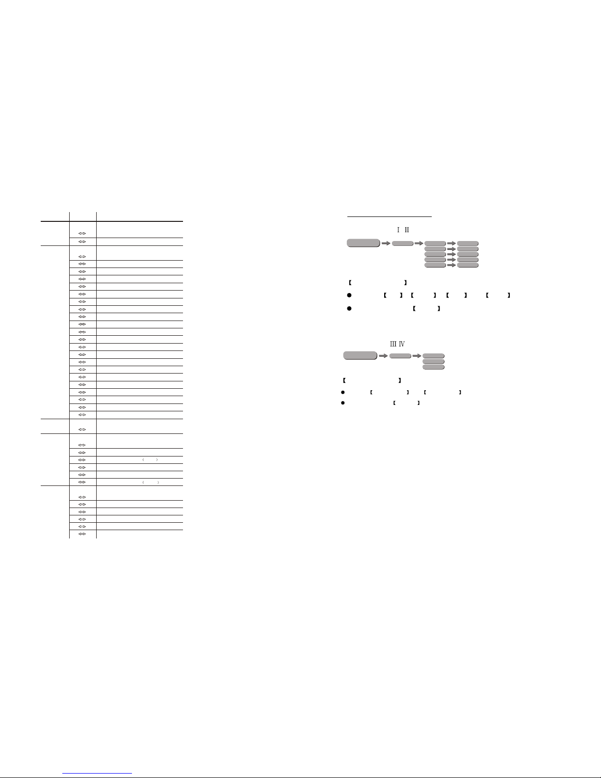
3.3 EDIT STATIC COLOUR
STATIC COLOUR
Combine Red , Green , Blue and White to create an infinite
range of colors (0-255)
Set the value of the Strobe (0-20Hz)
MENU Red
Green
Blue
White
(0~255)
(0~255)
(0~255)
(0~255)
Strob (0~20)
STAT
MENU W(0~255)
C(0~255)
ST(0~20)
STAT
STATIC COLOUR
Combine and to create whites with different
color temperature
Set the valueof the STROBE (0-20Hz)
WARM WHITE COOL WHITE
CHANNEL FUNCTIONVALUE
7
8
0 10
1~20Hz
11 255
CUSTOM 2
CUSTOM 3
CUSTOM 4
CUSTOM 5
CUSTOM 6
CUSTOM 7
CUSTOM 8
CUSTOM 9
CUSTOM 10
121 130
131 140
141 150
151 160
161 170
171 180
181 190
191 200
201 210
CUSTOM 1
211 220
221 255
71 80
81 90
91 100
101 110
AUTO 6
AUTO 7
AUTO 8
AUTO 9
111 120 AUTO 10
0 20
21 30
31 40
41 50
51 60
61 70
AUTO 1
AUTO 2
AUTO 3
AUTO 4
AUTO 5
0 255
9
DIMMER SPEED
LINEAR DIMMER
NON LINEAR DIMMER 1 fastest
10 29
30 69
70 129
130 189
190 255
10
NON LINEAR DIMMER 2
NON LINEAR DIMMER 3
NON LINEAR DIMMER 4 slowest
ID1~ID66
ID1
ID2
ID3
ID4
ID5
0 9
10 19
20 29
30 39
40 49
50 59
11
NO FUNCTION
AUTO
NO FUNCTION
STROBE
NO FUNCTION
ID ADDRESS
AUTO SPEED ADJUSTMENT
When using CH8,AUTO01-AUTO10, this function activated
0 9 PRESET DIMMER SPEED FROMDISPLAY MENU
APPLY:(Type- / )
APPLY:(Type- / )
10
15
3.4 ACTIVATING AUTO PROGRAMS
AUTO
Select the target AUTO program and press ENTER .
Programs AT.0 1 to AT.1 0 are fully pre-programmed and will not be
altered by changes in EDIT mode.
Programs PR.01 to PR.10 are fully pre-programmed and can be edited
in EDIT mode.
AT.01
AT.02
AT.10
AUTO
PR.01
PR.02
PR.10
MENU
RUN
Enter the RUN mode to set working mode.
DMX mode is for using the DMX512 controller to control the fixtures.
SLAV mode is for Master -- Slave operation.
3.5 RUN MODE
RUN DMX
SLAV
MENU
3.6 DMX512 SETTINGS
DMX
Enter the DMX mode to set the DMX ADDRESS.
D(001~512)
DMX
MENU
Note: This product have threeDMX512 channel configuration:
TOUR , Arc.1 , Ar1.d , Arc.2 , Ar2.d , Ar2.s and
HSV
TOUR
1
2
0 255
3
4
0 255
0 255
0 255
50 255
CHANNEL FUNCTIONVALUE
BLUE
WHITE
GREEN
(or FADE TIME when CUS.01-CUS.10 in CH8 is activated)
RED
(or STEP TIME when CUS.01-CUS.10 in CH8 is activated)
MASTER DIMMER
6
WHITE1 3200K
WHITE2 3400K
WHITE3 4200K
WHITE4 4900K
WHITE5 5600K
WHITE6 5900K
205
RED100%/GREEN 100%P/BLUE100%/WHITE 100%
RED 0%/GREEN DOWN/BLUE 100%
RED UP/GREEN 0%/BLUE100%
RED100%/GREEN 0%/BLU EDOWN
RED100%/GREEN UP/BLUE UP
RED DOWN/GREEN DOWN/BLUE 100%
RED100%/GREEN UP/BLUE0%
RED DOWN/GREEN 100%/BLUE0%
RED 0%/GREEN 100%/BLUE UP
COLOR MACRO
231 235
236 240
241 245
246 250
251 255
WHITE 7: 6500K
WHITE 8: 7200K
WHITE 9: 8000K
WHITE 10: 8500K
WHITE 11: 10000K
4.21 CHANNEL ASSIGNMENT
Connect all of the unitsin series using standard DMX512 signal cable or
the IP65 rated cable provided.
Set the DMX512address in the DMX menu.
It is possible to have the same DMX address or independent
addresses for eachfixture.
4.1 BASIC ADDRESSING
4 USING A DMX512 CONTROLLER
APPLY:(Type- / )
APPLY:(Type- / / / )
APPLY:(Type- / / / )
APPLY:(Type- / )
14 11
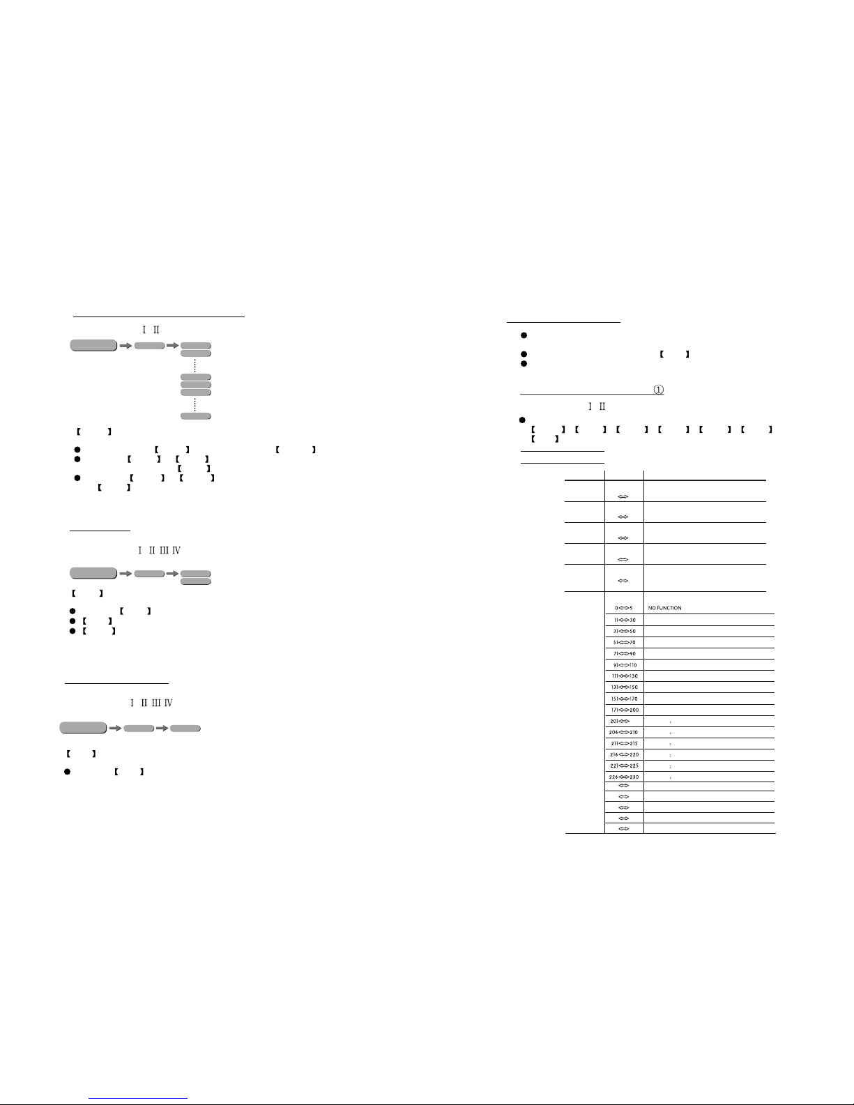
3.7 PERSONALITY
PERSONALITY
Enter the PERSONALITY mode to select DMX mode: TOUR , Arc.1 ,
Ar1.d , Arc.2 , Ar2.d , Ar2.s or HSV .
MENU
TOUR
Arc.1
Arc.2
Ar1.d
Ar2.s
Ar2.d
PERS
HSV
STd.d
STd.2
STd.1
PERS STd.w
UNO
MENU
PERSONALITY
Enter the PERSONALITY mode to select DMX mode: STD.W , STD.D ,
STD.1 , STD.2 or UNO .
3.8 ID ADDRESS
ID
Enter the ID mode to set the ID ADDRESS.
ID
ID(01~66)
MENU
KEY ON
OFF
MENU
3.13 ACTIVATE THE PASSWORD
KEY
Enter the KEY mode to select whether the access password is on or off.
When the fixture is set as PASS ON , after 30 seconds or turn on the fixture
next time, the fixture will need an access password to enter the display menu
control.
Note: The factory access password is UP +DOWN +UP +DOWN ,
then press ENTER to confirm the access.
WT01
WT02
WT05
CAL1 W(0~255)
C(0~255)
MENU
CAL1
Enter the CAL1 to select white color of different color temperature.
There are 5 pre-programmed White colors can be edited by using
WARM WHITE & COOL WHITE .
APPLY:(Type- / )
APPLY:(Type- / )
APPLY:(Type- / / / )
APPLY:(Type- / / / )
APPLY:(Type- / )
CAL2
Enter the CAL2 to adjust the RGB parameter to make different whites.
CAL2
When the new setting is activated, the DMX controller choose
RGB = 255,255,255, the white color will be made by the actual RGB values on
the .
3.12 RGB CALIBRATION
RGBW Red
Green
Blue
(0~255)
(0~255)
(0~255)
CAL2
MENU
APPLY:(Type- / )
12 13
SET UPLd
Id ON
OFF
REST
dIM1
dIM3
dIM2
dIM4
dIM
OFF
MENU
SETTING
Select UPLD to upload thecustom programs fromthe current MASTERunit to the
SLAVE units.
In order toactivate the uploadfunction the passwordmust be entered.
Password is thesame as themain access password.
When uploading theMASTER and SLAVE units willbe black out.
On successful uploadingof the customprograms the MASTERand SLAVE units will
display Cool White.
In order toreset custom modesto default valuesselect REST .
Enter ID in order toallow/disallow ID addressfunction from theDMX512
controller.
Enter dIM to select dimmermode and dimmerspeed. When DIMMERis set to Off ,
then RGBW and MASTER DIMMER are linear. TheDim 1/2/3/4 arespeed
modes of the non linear dimmer , dIM1 is the faster, while dIM4 is the slowest.The
factory default setting is dIM4 .
MENU
3.10 SPECIAL SETTINGS
SET UPLD
ID ON
OFF
REST
RGBW
COLOR
Dim1
Dim3
Dim2
Dim4
Dim
UC
OFF
Off
SETTING
Select UPLD to upload thecustom programs fromthe current MASTERunit to
the SLAVEunits.
In order toactivate the uploadfunction the passwordmust be entered.
Password is thesame as themain access password.
When uploading theMASTER and SLAVE units willdisplay YELLOW.
If an erroroccurs when uploadingthe MASTER and/orSLAVE units will display RED.
On successful uploadingof the customprograms the MASTERand SLAVE units
will display GREEN.
In order toreset custom modesto default valuesselect REST .
Enter ID in order toallow/disallow ID addressfunction from theDMX512
controller.
COLOR is for activate/unactivate the color calibration functions.
When RGBW is selected, onRGB = 255,255,255, the color isdisplayed as calibrated
in CAL2 --RGBW. When COLOR is set OFF , on RGB= 255,255,255, the RGB
values are notadjusted and the output is mostpowerful.
When [UC] is selected, the RGB output are adjusted toa standard presetuniversal color
which balances fixturesfrom different generations..
Enter Dim to select dimmer mode and dimmer speed. When DIMMER is
set to Off , then RGBWand MASTER DIMMERare linear. The Dim 1/2/3/4
are speed modesof the nonlinear dimmer , Dim1 is the faster, while
Dim4 is the slowest.
The factory default setting is Dim4 .
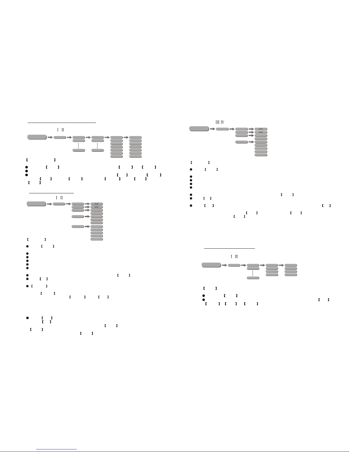
3.9 EDITING CUSTOM PROGRAMS
PR.01
PR.02
PR.10
SC.01
SC.02
SC.30
Red
Green
Blue
White
Strobe
Time
Fade
(0~255)
(0~255)
(0~255)
(0~255)
(0~20)
(0~255)
(0~255)
EDIT
MENU
EDIT CUSTOM
Enter the EDIT mode to edit the custom programs PR.01 to PR.10 .
Each custom programhas 30 stepsthat can be edited.
Each step allowsthe creation ofa scene using RED Red , GREEN Green ,
BLUE Blue , WHITE White , STROBE Strobe , TIME Time & FADE
Fade .
APPLY:(Type- / )
APPLY:(Type- / )
APPLY:(Type- / )
3.11 WHITES CALIBRATION
WT01
WT02
WT11
Red
Green
Blue
White
(0~255)
(0~255)
(0~255)
(0~255)
CAL1
MENU
CAL1
Enter the CAL1 to select white color of different color temperature.
There are 11 pre-programmed White colors can be edited by using Red ,
Green , Blue & White .
APPLY:(Type- / )
Table of contents
Other SSP Lighting Equipment manuals


Popular Lighting Equipment manuals by other brands

Larson Electronics
Larson Electronics GAU-HB-160LED instruction manual

Cree
Cree OSQ Series installation instructions

Somogyi Elektronic
Somogyi Elektronic home FLP5SOLAR instruction manual

Viessmann
Viessmann 5224 manual

X-Cite
X-Cite WPS BULKHEAD Installation & operating instructions

Rush
Rush STROBE 1 5x5 user manual


