SSP ROXCYC/TZ User manual

ROXCYC/TZROXCYC/TZROXCYC/TZROXCYC/TZ
YG-LED317
USER MANUAL

ABLE OF CONTENTS
T
PART 1 PRODUCT (GENERAL)................................................................. 1.
1.1--TECHNICAL SPECIFICATIONS................................................................... 1.
1.2--SAFETY WARNING.....................................................................................2.
PART 2 INSTALLATION ............................................................................3.
2.1--MOUNTING................................................................................................ 3.
2.2--POWER CONNECTIONS.............................................................................3.
PART 3 DISPLAY PANEL OPERATION.......................................................4.
3.1--BASIC........................................................................................................4.
3.2--MENU...................................................................................................... .4.
3.3--STATIC......................................................................................................6.
3.4--AUTO PLAYMODE.....................................................................................6.
3.5-- DMX ADDRESS.........................................................................................7.
3.6--RUN MODE................................................................................................7.
3.7--PERSONALITY...........................................................................................7.
3.8--ID ADDRESS..............................................................................................7.
3.9--SPECIAL SETTINGS ..................................................................................8.
3.10--FACTORYDEFAULTSETTING...................................................................9.
3.11--EDIT CUSTOM.........................................................................................9.
3.12-- WHITES SETTING.................................................................................10.
3.13--FAN SETTING........................................................................................10.
3.14--ACTIVATETHE PASSWORD....................................................................10.
.
PART 4 USING ADMX512 CONTROLLER..................................................11.
4.1--BASIC ADDRESSING................................................................................. 11.
4.21--CHANNEL ASSIGNMENT.......................................................................... 11.
4.3--BASIC INSTRUCTIONS FOR DMX512 OPERATION(TOUR) ....................... 17.
4.4--BASIC INSTRUCTIONS FOR DMX512 OPERATION (BLOCK 1 & 2).............. 17.
PART 5 APPENDIX..................................................................................18.
5.1--MAINTENANCE........................................................................................18.
17
4.3 BASIC INSTRUCTIONS FOR DMX512
OPERATION (TOUR)
MASTER DIMMER
CH1 controls theintensity of thecurrently projected color
When the slideris at thehighest position (255) the intensity of the output is the
maximum
RED, GREEN BLUE, WHITE & AMBER COLOR SELECTION
CH2, CH3 &Ch4, Ch5 &CH6 control the intensity ratio of each of the RED,
GREEN, BLUE, WHITE& AMBER LEDs.
When the slideris at thehighest position (255) the intensity of the color is the
maximum.
CH2, CH3, Ch4, Ch5 &CH6can be combined together to create over 16
million colors.
COLOR MACROS AND WHITE BALANCE
CH7 selects therequired COLOR MACROand whites indifferent color temp.
Ch7 has priorityover CH2, CH3, CH4, CH5 ,Ch6 & CH9.
CH1 is usedto control theintensity of the COLOR MACRO
STROBE
CH 8 controlsthe strobe of CH2 to CH7.
ID ADDRESS SELECTION
CH12 is usedto select thetarget ID address.
Each independent DMXaddress may haveupto 66 independent ID addresses.
An IDaddress of 0will activate all ID address locations.
AUTO
CH9 selects thepreset AUTO programsAUTO 1-AUTO10 or the custom
programs CUSTOM1-CUSTOM 10.
Ch9 has priorityover Ch2, Ch3,Ch4 , Ch5 & Ch6..
BLOCK SELECTION
Ch13 channel allowsthe user to select from combinationsof different
colors and LEDblocks in aquick-and-easy action
4.4 BASIC INSTRUCTIONS FOR DMX512
OPERATION (BLOCK 1 & 2)
BLOCK 1
All ledsdivided as 3blocks, each blockinclude 6 redleds, 6 greenleds and 6
blue leds.
BLOCK2
All ledsdivided as 3blocks, each blockinclude 6 redleds, 6 greenleds, 6 blue
leds, 3 whiteleds and 3amber leds.
4.22--CHANNEL ASSIGNMENT........................................................................ . 16.
1
16
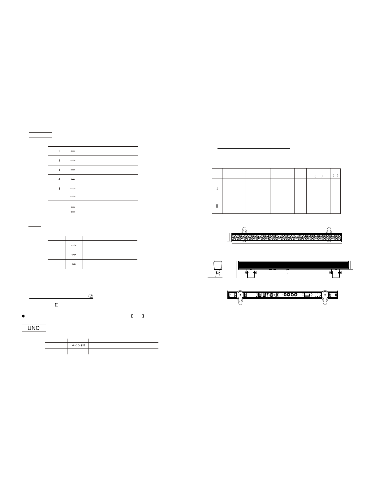
1PRODUCT (GENERAL)
990mm
75mm
156mm
77mm
1.1 TECHNICAL SPECIFICATIONS
LED MODULE
Model
AC100~240V
50/60Hz -20~40 6990x156x75
Voltage Operation
Temperature
Weight
Dimensions 2
mm
Power
W
R:1Wx18
G:1Wx18
B:1Wx18
W:1Wx9
CW:1Wx36
WW:1Wx36
A:1Wx9 87
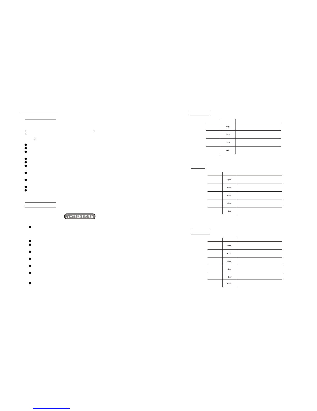
1
2
0 255
3
0 255
0 255
HSV
HUE
SATURATION
VALUE
CHANNEL VALUE FUNCTION
0 255
0 255
0 255
0 255 BLUE
ARC 2+S
MASTER DIMMER
RED
GREEN
VALUE FUNCTION
0 255 WHITE
60 255 AMBER
70 9 NO FUNCTION
1~20Hz
10 255
STROBE
CHANNEL
Type
ZOOM
1
4.22 CHANNEL ASSIGNMENT
APPLY:(Type- )
Note: This product have oneDMX512 channel configuration: UNO
CHANNEL VALUE FUNCTION
1.2 SAFETY WARNING
IMPORTANT
ALWAYS READ THE USER MANUAL BEFORE OPERATION.
PLEASE CONFIRM THAT THE POWER SUPPLY STATED ON THE
PRODUCT IS THE SAME AS THE MAINS POWER SUPPLY IN YOUR
AREA.
This product must be installed by a qualified professional.
Always operatethe equipment asdescribed in theuser manual.
A minimum distance of 0.5m must be maintained between the
equipment and combustiblesurface.
The product must always be placed in a well ventilated area.
Always makesure that the equipment is installed securely.
DO NOT stand close to the equipment and stare directly into the LED
light source.
Always disconnect the power supply before attempting and
maintenance.
Always make sure that the supporting structure is solid and can
support the combinedweight of theproducts.
The earth wire must always be connected to the ground.
Do not touchthe power cablesif your handsare wet.
ATTENTION
This product left the placeof manufacture inperfect condition. In
order to maintainthis condition and for safe operation, the user must
always follow theinstructions and safety warnings described in this
user manual.
Avoid shaking or strongimpacts to anypart of theequipment.
Make sure thatall parts of the equipment are kept clean and free of
dust.
Always makesure that the power connections are connected correct
and secure.
If there isany malfunction of the equipment, contact your distributor
immediately.
When transferring theproduct, it is advisable to use the original
packaging in whichthe product left the factory.
Shields, lenses orultraviolet screens shall be changed if they have
become damaged tosuch an extent that their effectiveness is
impaired.
The lamp (LED) shall bechanged if ithas become damagedor
thermally deformed.
15
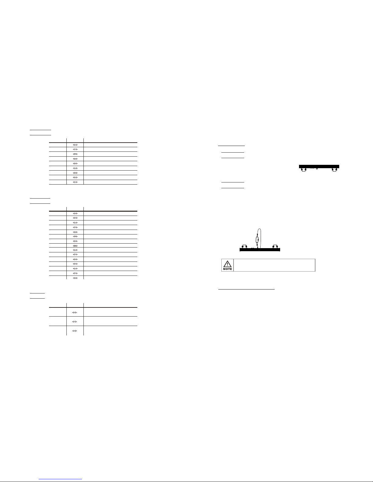
2
1
2
0 255
3
4
0 255
0 255
0 255 BLUE
ARC 2+D
MASTER DIMMER
RED
GREEN
VALUE FUNCTION
50 255 WHITE
60 255 AMBER
CHANNEL
1
2
0 255
3
4
0 255
0 255
0 255 BLUE
MASTER DIMMER
RED
GREEN
VALUE FUNCTION
CHANNEL
ARC 1+D
1
2
0 255
3
4
0 255
0 255
0 255
BLUE
ARC 2
RED
GREEN
VALUE FUNCTION
50 255
WHITE
AMBER
CHANNEL
2.1 MOUNTING
UPRIGHT
The LED MODULE can be
mounted in anupright or sitting
position using the supporting
brackets.
@ 220V: 12 units may be connected in series
@120V: 6 units may be connected in series
The LED MODULE canbe mounted at anyangle . It ispossible to
further adjust the angleof the LED MODULEusing the
adjustment knobs located onthe side of thefixture.
2.2 POWER CONNECTIONS
HANGING
The LED MODULEcan be mountedin a hangingposition using
the support frame. It is possibleto use any bolt of the correct
size and strengthto mount thefixture. It isrecommended to
use at least2 mounting pointsper fixture. Mountingwith a
clamp or othermounting bracket isrecommended depending
on the requirementsof your application.
For overhead use,always install twosecure-chains that can
hold at least10 times theweight of thefixture.
2INSTALLATION
Note: If over 30units to beconnected, then aDMX signal amplifier
is needed.
3
14
BLOCK1 RED
BLOCK1 GREEN
BLOCK1 BLUE
0 255
0
0
255
255
0 255
0 255
0 255
0 255
0
0
255
255
1
2
3
4
5
6
7
8
9
BLOCK1
14
15
0 255
0
0
255
255
0 255
0 255
0 255
0 255
0
0
255
255
0 255
0 255
1
2
3
6
7
8
11
12
13
BLOCK2
0 255
0 255
4
5
0 255
0 255
9
10
ARC 1
VALUE FUNCTION
CHANNEL
BLOCK2 RED
BLOCK2 GREEN
BLOCK2 BLUE
BLOCK3 RED
BLOCK3 GREEN
BLOCK3 BLUE
BLOCK1 RED
BLOCK1 GREEN
BLOCK1 BLUE
BLOCK1 WHITE
BLOCK1 AMBER
BLOCK2 RED
BLOCK2 GREEN
BLOCK2 BLUE
BLOCK2 WHITE
BLOCK2 AMBER
BLOCK3 RED
BLOCK3 GREEN
BLOCK3 BLUE
BLOCK3 WHITE
BLOCK3 AMBER
1
3
4
0 255
0 255
0 255 BLUE
RED
GREEN
VALUE FUNCTION
CHANNEL
VALUE FUNCTION
CHANNEL

UP
ENTER DOWN
MENU
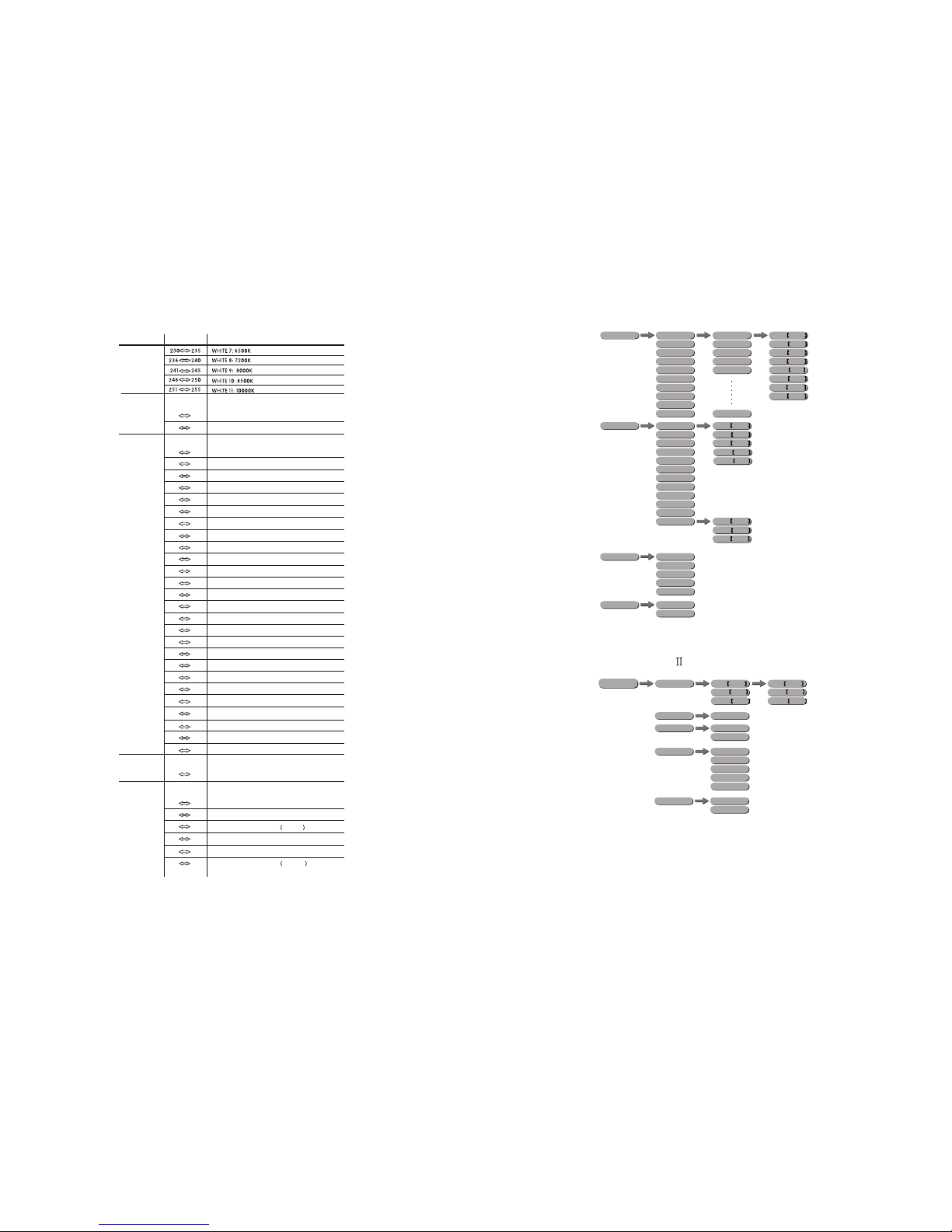
3.2 MENU
RUN
PERSON
SLAVE
DMX
ADDERSS
TOUR
BLOCK1
BLOCK2
ARC 1
ID
1~66
1~512
ARC 1+D
ARC 2
STATIC
GREN 0~255
RED 0~255
BLUE 0~255
WHIT 0~255
AMBE 0~255
STRB 0~020
ARC 2+D
ARC 2+S
GREN 0~255
RED 0~255
BLUE 0~255
WHIT 0~255
AMBE 0~255
STRB 0~020
SETTINGS
UPLOAD
PASSWORD
RESET
PASSWORD
ID ONOFF
OFF
ON
**** SEND... END
**** RESET...
DIMMER
DIM1
OFF
DIM3
DIM2
DIM4
COLOR
RGB TO W
OFF
UC
HSV
MENU
enter the currently selectedmenu or confirm thecurrent function value
scroll 'UP' through the menu list or increase thevalue of the current function
scroll 'DOWN' through the menu list or decrease the value of the current function
scroll through the mainmenu or return tothe main menu
MENU
ENTER
3.1 BASIC
3 DISPLAY PANEL OPERATION
AUTO AUTO 01
AUTO 10
CUSTOM 01
CUSTOM 02
CUSTOM 03
CUSTOM 04
CUSTOM 05
CUSTOM 06
CUSTOM 07
CUSTOM 08
CUSTOM 09
CUSTOM 10
SP 0~255
13
4
12
ID ADDRESS
ID1~ID66
ID1
ID2
ID3
ID4
ID5
ID6
ID7
ID8
ID9
ID10
ID11
ID12
ID13
ID14
0 9
10 19
20 29
30 39
40 49
50 59
60 69
70 79
80 89
90 99
100 109
110 119
120 129
130 139
140 149
ID19
ID20
190 199
200 209
ID21
ID22
210
211
ID65
ID66
254
255
ID15
ID16
ID17
150 159
160 169
170 179
ID18180 189
13
BLOCK SELECTIONS
BLOCK1, BLOCK2, BLOCK3
0 4
5 34
35 64
65 94
95 124
125 154
155 184
215 255
BLOCK1
BLOCK2
BLOCK3
BLOCK1, BLOCK2
BLOCK2, BLOCK3
BLOCK1, BLOCK3
185 241 BLOCK1, BLOCK2, BLOCK3
NO FUNCTION
VALUE FUNCTION
CHANNEL
APPLY:(Type- )
EDIT CUSTOM 01
CUSTOM 02
CUSTOM 03
CUSTOM 04
CUSTOM 05
CUSTOM 06
CUSTOM 07
CUSTOM 08
CUSTOM 09
CUSTOM 10
SCENE 01
SCENE 02
SCENE 03
SCENE 04
SCENE 05
SCENE 30
GREN 0~255
RED 0~255
BLUE 0~255
STRB 0~020
TIME 0~255
FADE 0~031
WHIT 0~255
AMBER 0~255
WHITE1
WHITE2
WHITE3
WHITE4
WHITE5
WHITE6
WHITE7
WHITE8
WHITE9
WHITE10
WHITE11
RGB TO W
GREN 0~255
RED 0~255
BLUE 0~255
CALIB
FANS OFF
LOW
NORMAL
HIGH
AUTO
KEYLOCK
OFF
ON
WHITE 0~255
AMBER 0~255
GREN 0~255
RED 0~255
BLUE 0~255
5
12
RUN
SLAVE
DMX
ADDERSS
1~512
STATIC
COOL 0~255
DIM 0~255
WARM 0~255
COOL 0~255
DIM 0~255
WARM 0~255
MENU
FANS OFF
LOW
NORMAL
HIGH
AUTO
KEYLOCK
OFF
ON
0 255
AUTO SPEED
10
AUTO SPEED FOR Auto1~Auto10
Auto 6
Auto 7
Auto 8
Auto 9
111 120
Auto 10
121 130
131 140
141 150
151 160
161 170
Custom 2
Custom 1
171 180
181 190
191 200
201 210
211 220
0 9
10 29
30 69
70 129
Custom 3
Custom 4
Custom 5
Custom 6
0 10
11 20
21 30
31 40
41 50
9
61 70
81 90
91 100
101 110
Auto 1
Auto 2
Auto 3
Auto 4
Auto 5
71 80
51 60
80 9
10 255
11
130 189
190 255
221 230 Custom 7
231 240 Custom 8
241 250 Custom 9
251 255 Custom 10
1~20Hz
NO FUNCTION
STROBE
FANS OFF (STAY 3 SECONDS)
FANS LOW (STAY 3 SECONDS)
FANS NORMAL (STAY 3 SECONDS)
FANS HIGH (STAY 3 SECONDS)
FANS AUTO(STAY3 SECONDS)
AUTO + CUSTOM PROGRAMS+ FAN CONTROL
NO FUNCTION
DIMMER SPEED
LINEAR DIMMER
NON LINEAR DIMMER 1 fastest
NON LINEAR DIMMER 2
NON LINEAR DIMMER 3
NON LINEAR DIMMER 4 slowest
PRESET DIMMER SPEED FROMDISPLAY MENU
7
VALUE FUNCTION
CHANNEL
APPLY:(Type- )

11
6
MENU
AUTO PLAY MODE
Select the target Auto program .
Programs AUTO 01 to AUTO 10 are fully pre-programmed and will not be
altered by changesin EDIT CUSTOM mode. Theauto speed canbe set from
SP 1~255 .
Programs CUSTOM 01 to CUSTOM10 are fully pre-programmedand can
be edited in EDIT CUSTOM mode.
AUTO AUTO 01
AUTO 10
CUSTOM 01
CUSTOM 02
CUSTOM 03
CUSTOM 04
CUSTOM 05
CUSTOM 06
CUSTOM 07
CUSTOM 08
CUSTOM 09
CUSTOM 10
SP 0~255
3.4 AUTO PLAY MODE
3.3 STATIC
STATIC COLOUR
Combine Red , Green , Blue , White and Amber to create
an infinite range of colors (0-255)
Set the value of the Strobe (0-20Hz)
STATIC
GREN 0~255
RED 0~255
BLUE 0~255
WHIT 0~255
AMBE 0~255
STRB 0~020
GREN 0~255
RED 0~255
BLUE 0~255
WHIT 0~255
AMBE 0~255
STRB 0~020
MENU
STATIC
COOL 0~255
DIM 0~255
WARM 0~255
COOL 0~255
DIM 0~255
WARM 0~255
MENU
STATIC COLOUR
Combine DIM , COOL and WARM
to createan infinite range of colors (0-255)
TOUR
Note: This product have threeDMX512 channel configuration:
TOUR , BLOCK1 , , ARC 1 , ARC 1+D ,
2, 2 and HSV
BLOCK2 ARC
ARC +D
4.1 BASIC ADDRESSING
Connect all of the unitsin series using standard DMX512 signal cable or
the IP65 rated cable provided.
Set the DMX512address in the DMX menu.
It is possible to have the same DMX address or independent
addresses for eachfixture.
4.21 CHANNEL ASSIGNMENT
4 USING A DMX512 CONTROLLER
1
2
3
4
COLOR MACRO + WHITE BALANCE
5
6
BLUE
MASTER DIMMER
RED
GREEN
VALUE FUNCTION
WHITE
AMBER
CHANNEL
7
APPLY:(Type- )
APPLY:(Type- )
APPLY:(Type- )
APPLY:(Type- )

3.8 ID ADDRESS
ID ADDRESS
Enter the ID ADDRESS mode to set the ID ADDRESS.
ID
1~66
MENU
7
10
3.7 PERSONALITY
3.5 DMX ADDRESS
DMX ADDRESS
Enter the DMX ADDRESS mode to set the DMX ADDRESS.
RUN MODE
Enter the RUN MODE mode to setworking mode.
DMX mode is forusing the DMX512controller to controlthe fixtures.
SLAVE mode is forMaster -- Slaveoperation, or controlledfixture by
Pix-controller.
Note: When fixtures areunder Autoprogram operation, the RUN MODE does
no works.
3.6 RUN MODE
PERSONALITY
Enter the PERSONALITY mode to select DMX mode: ,
,,, ,, ,
or .
ADDERSS
1~512
MENU
RUN
SLAVE
DMX
MENU
PERSON TOUR
BLOCK1
BLOCK2
ARC 1
ARC 1+D
ARC 2
ARC 2+D
ARC 2+S
HSV
MENU
KEY-LOCK
Enter the KEY-LOCK mode to selectwhether the access password is on
or off.
Access passwordis UP +DOWN +UP +DOWN .
3.14 ACTIVATE THE PASSWORD
KEYLOCK
OFF
ON
MENU
WHITE1
WHITE2
WHITE3
WHITE4
WHITE5
WHITE6
WHITE7
WHITE8
WHITE9
WHITE10
WHITE11
RGB TO W
GREN 0~255
RED 0~255
BLUE 0~255
CALIB
MENU
3.12 WHITES SETTING
WHITE 0~255
AMBER 0~255
GREN 0~255
RED 0~255
BLUE 0~255
WHITE CALIB
Enter the WHITE CALIB to select white color of differentcolor temperature.
There are 11 pre-programmed Whitecolors can beedited by using Red ,Green ,
Blue , White and Amber , and RGB TO WHITE by using Red , Green
and Blue .
3.13 FAN SETTING
FAN SETTING
Enter the FAN SETTING to select thefan speed mode OFF ,
LOW , NORM ,HIGH or AUTO .
When fan settingis on AUTO mode, the fixture will automatic adjust the
fan speed and fixture power, ensure the fixturetemperature is not exceed
the limit.
When fan settingis on other modes, the fan will run according to the set
speed.
.
FANS OFF
LOW
NORMAL
HIGH
AUTO
MENU
APPLY:(Type- )
APPLY:(Type- / )
APPLY:(Type- / )
APPLY:(Type- / )
APPLY:(Type- / )
APPLY:(Type- )
APPLY:(Type- )

EDIT CUSTOM 01
CUSTOM 02
CUSTOM 03
CUSTOM 04
CUSTOM 05
CUSTOM 06
CUSTOM 07
CUSTOM 08
CUSTOM 09
CUSTOM 10
SCENE 01
SCENE 02
SCENE 03
SCENE 04
SCENE 05
SCENE 30
GREN 0~255
RED 0~255
BLUE 0~255
STRB 0~020
TIME 0~255
FADE 0~031
WHIT 0~255
AMBER 0~255
MENU
3.11 EDIT CUSTOM
3.10 FACTORY DEFAULT SETTING
2
3
4
5
7
8
9
DMX address = 001
ID ON/OFF = ON
COLOR = OFF
KEYLOCK = OFF
Parsonaliey = TOUR
Run mode = DMX
10 Fan = Auto
1STATIC =000
ID address = 001
6
DIMMER = DIM4
EDIT = 000
11
EDIT CUSTOM
Enter the EDIT CUSTOM mode to edit the custom programs
to
Each custom programhas 30 steps that can be edited.
Each step allowsthe creation of a scene using RED RED , GREEN
GREEN , BLUE BLUE ,WHITE WHITE , AMBER AMBER ,
STROBE Stro. , TIME TIMER & FADE FADE .
CUSTOM 1
CUSTOM 10 .
9
8
3.9 SPECIAL SETTINGS
SETTINGS
UPLOAD
PASSWORD
RESET
PASSWORD
ID ONOFF
OFF
ON
**** SEND... END
**** RESET...
DIMMER
DIM1
OFF
DIM3
DIM2
DIM4
COLOR
RGB TO W
OFF
UC
MENU
SETTING
Enter ID in order to allow/disallow ID address function from theDMX512
controller.
Select UPLD to upload the custom programs from the current MASTERunit to
the SLAVEunits.
In order toactivate the uploadfunction the passwordmust be entered.
Password is thesame as themain access password.
When uploading theMASTER and SLAVE units willdisplay YELLOW.
If an erroroccurs when uploadingthe MASTER and/orSLAVE units will display RED.
On successful uploadingof the customprograms the MASTERand SLAVE units
will display GREEN.
In order toreset custom modesto default valuesselect REST .
Enter Dim to select dimmer mode and dimmer speed. When DIMMER is
set to Off , then RGBWand MASTER DIMMER are linear. The Dim 1/2/3/4
are speed modesof the non linear dimmer , Dim1 is the faster, while
Dim4 is the slowest.
The factory default setting is Dim4 .
COLOR is for activate/unactivate the color calibration functions.
When RGBW is selected, onRGB = 255,255,255, the color is displayed as
calibrated in CAL2 -- RGBW. When COLOR is set OFF , on RGB = 255,255,
255, the RGB values are not adjusted and the output is most powerful.
When [UC] is selected,the RGB outputare adjusted toa standard presetuniversal color
which balances fixturesfrom different generations..
APPLY:(Type- )
APPLY:(Type- )
APPLY:(Type- )
Table of contents
Other SSP Lighting Equipment manuals


