SSS Siedle novotechnik MAP 300 User manual

Siedle Group
Novotechnik
Messwertaufnehmer OHG
Postfach 4220
73745 Ostfildern (Ruit)
Horbstraße 12
73760 Ostfildern (Ruit)
Telefon 0711/44 89-0
Telefax 0711/44 89-118
http://www.novotechnik.de
MAP300_400_en_01.doc
LENGTH- AND ANGLE-
MEASURING SYSTEMS MAP 300/400
CONTENTS (44/00)
1 SAFETY INSTRUCTIONS
page 3
1.1 WARNINGS 3
1.2 EMI-INSTALLATION POINTERS 4
1.3 UNIT POINTERS 4
2 FOUNDATIONS
5
2.1 APPLICATION 5
2.2 FUNCTION 5
2.3 SCHEMATIC DIAGRAM 5
2.4 CONNECTING CABLE 6
2.5 FEATURES 6
2.6 OPTIONS 6
3 SETUP MENU
7
3.1 LIMIT VALUE FUNCTION 7
3.2 INPUT FUNCTION 8
3.2.1 Taring function 9
3.2.2 Storage functions 10
3.2.3 Blocking functions 10
3.2.4 Peakdetector 11
3.2.5 BCD- or HEX-inquiry 11
3.2.6 Print start 11
3.2.7 Display dark function 11
3.2.8 Closed-circuit current function for outputs 12
3.2.9 Limit value acceptance 12
3.3 INTERFACE FUNCTION (RS232) 12
3.4 MEASURING RANGE 13
3.5 CALIBRATION 14
3.6 ANALOG OUTPUT (OPTION) 15

Siedle Group
Novotechnik
Messwertaufnehmer OHG
MAP300_400_en_01.doc
2
4 FUNCTION MENU
page 16
4.1 MEASURING RATE 16
4.2 DISPLAY FUNCTION 16
4.3 DECIMAL POINT 17
4.4 TARING VALUE 17
4.5 HYSTERESIS VALUE 17
4.6 TIME / DATE (OPTION) 17
5 LIMIT VALUES
18
5.1 LIMIT VALUE PROGRAMMING 18
5.2 RELAY CONTACT OUTPUT 18
5.3 OPTOCOUPLER OUTPUT 18
6 INFO MENU
19
7 AUXILIARY OUTPUT
21
8 ERROR MESSAGES
21
9 TECHNICAL DATA
22
10 CONNECTION / OPERATING CONTROLS
24
11 DESCRIPTION IN/OUTPUTS
25

Siedle Group
Novotechnik
Messwertaufnehmer OHG
MAP300_400_en_01.doc
3
1 SAFETY INSTRUCTIONS
1.1 WARNINGS
•Operating Instructions
For a safety operating of this unit you have to read first the operating instructions, the safety in-
structions and the warnings. During putting into operation you have to observe the succession of
the programming and the operating of the unit like
When you are putting the unit into operation you have to look after the succession of the manual.
Please follow the instructions for operation and use of the unit in all points. Please keep the
manual so that you can look up anything if you have to or an other person can also read it.
•Personal
Putting into operation of these measuring systems is only allowed for qualified and instructed
personal. Only EMI-qualified personal is allowed to put these units into operation. We will offer
on request trainings to the unit techniques and the operating.
•VDE-Instructions
During connecting the units you have to observe the instructions of the VDE and the instructions
of the professional association for working with electrical units and systems.
•Employment area
These units are only designed for operating in industrial applications. As standards EN 50081-2
and EN 50082-2 only allowed these units in industrial area.
•Supply of power
Please connect this unit only with the power supply, which is marked on the type sign.
•Attendance
Please do not try to open the screw caps. The guarantee is automatically null and void if they are
damaged. The unit is only allowed to be repaired by the producer. The user can eventual repairs
or rebuilds build only with the permission of the producer through. Before opening the unit remo-
ve all connection cables.
•Water and dampness
For prevention of fire or dangers by electrifying, you have to safe the unit before rain or damp-
ness. At sites of operations where it is the danger of water, which could penetrate into the front
side of the unit you have to fit the flexible protecting cap FSH (IP65). Please do not use the unit
near a wash bassin, kitchen sink, washing-machine, swimming pool or a damp room.
•Acclimatisation
When you lie down a unit at lower temperatures as they are in the operation room, you have to
lie down the unit first for two hours without power. It is possible that water will condense on the
electronic and this will be dangerous for persons and it could damage the unit.
•Penetrating alien elements
You have to look after that there cannot penetrate liquids or other alien elements like shavings,
soot or dust by the unit’s openings into the unit.
•Ventilation
The unit should be build in so that it could get enough ventilation.
•Heat effect
Do not fit the unit near of sources of heat or heat producing loads.
•Cleaning
Before cleaning the unit you should remove all connection cables. Please use only a low damp
rag. Other cleaning products can only be used after consultation with the producer.

Siedle Group
Novotechnik
Messwertaufnehmer OHG
MAP300_400_en_01.doc
4
1.2 EMI-INSTALLATION POINTERS
•Signal cables
Measuring, signal- or sensor cables, which are connected with the measuring system, must not
lie parallel to the power cables. Signal cables have to be screened over the whole length, so also
into a steer- or switch cabinet, and the screen connection has to be connected as it is described.
The screen connection of signal cables may be only connected one-sided or with reference
chassis.
•Power supply cable
The feeding of the units (direct voltage or alterning current) has to follow out of the same net,
which should be free from interference. Should the occasion arise you have to install a mains fil-
ter.
•Case
Metal cases in which the units will be installed have to be connected with reference chassis. The
non-fused earthed conductor has to be connected low-resistance.
•Distances
Around the unit there may be cables that carry a current only in a distance of minimum 10cm.
Radio installations or radio telephones should have a distance from minimum 2m to the unit. In-
terferencing ISM units or switching inductive load like conductors, magnetic rectifiers or motors
have to be suppressed from radio noise (RC- or varistor wiring) and should have a distance from
20cm.
1.3 UNIT POINTERS
•RS232-Interface
You have to look after, that the RS232-interface from the measuring input and the optional anal-
ogous output are not galvanically isolated.
•Auxiliary voltage output on AC-supply
You have to look after, that the auxiliary voltage output is not short-circuit-proof. An overload by
short-circuit leads to the responding of the overload protection of the intern transformer, which
will switch off. If required you should assign for an extern overload protection.
•Auxiliary voltage output on DC-supply
At units with 24V-supply (.8) the supply will be connected intern with the auxiliary voltage output.
By this the supply input and the auxiliary voltage output have the same reference potential. You
have to look after, that the auxiliary voltage output is not short-circuit-proof. If required, you
should assign for an extern overload protection.

Siedle Group
Novotechnik
Messwertaufnehmer OHG
MAP300_400_en_01.doc
5
2 FOUNDATIONS
2.1 APPLICATION
This series of measuring systems are used to display and monitor length and angle values. The
main applications are machine and test equipments.
2.2 FUNCTION
The units MAP 300/400 are microprocessor controled panel-mounting instruments with 3 3/4- to 4
3/4-digit display. The displayed reading can be programmed for the required measuring range. Four
independent limit value comparators monitor continuously for overshoot and undershoot of the pro-
grammed limits. The serial interface render the connection to a printer. Measurement value and
comparator state can be controlled additional with PC or PLC. With the four optoisolated logic in-
puts many different functions are controlable with external signals.

Siedle Group
Novotechnik
Messwertaufnehmer OHG
MAP300_400_en_01.doc
6
2.3 SCHEMATIC DIAGRAM
isolated
watchdog
voltage
monitoring
RS 232-
4x opto-
isolated
output
converter
/HEXBCD
limits
routine
peak-
detector
linearizat.
calibrat.
LED-
displays
switches
5x
output
input
2x
memory
limits
input
filter
relay
reference
output
anaolg
multiplexer converter
interface
serial
AD-
Z-960292
24 V DC
24 V DC
230 V AC
power supp.
4x opto-
auiliary
output
power supp.
software
filter
5 V DC
regulator
2.4 CONNECTING CABLE
All interfaces, for the measurement input, auxiliary output, logic in-/outputs, serial interface RS232
and the optional analog output are accessible on the rear side connectors. The connecting cables
for sensor, analog output and RS 232 interface must be shielded. The shield must be connected to
the corresponding terminal (see 10 CONNECTION). It is not allowed to connect the shield at the
other cable end to any potential, because that generates a disturbing cable loop. This prevents the
optimal function of the unit.
It is not allowed to lay the power and control cables of the unit in the near of power plants, electric
welding cables or supply cables for inductive components like motors, magnets, frequency trans-
formers etc.

Siedle Group
Novotechnik
Messwertaufnehmer OHG
MAP300_400_en_01.doc
7
2.5 FEATURES
The measurement systems have different features. Therefore the service of the units is naturally a
little bit different. I. ex. units without limit value comparators have no programmable functions like
„LIMIT VALUE FUNCTION“ or „LIMIT VALUE PROGRAMMING“. In special chapters that is addi-
tional noted.
The following table shows the different features:
features MAP 444 MAP 344 MAP 342 MAP 340 MAP 334 MAP 332 MAP 330
display range -9999/40000 -9999/20000 -9999/20000 -9999/20000 -4000/4000 -2000/2000 -2000/2000
accuracy 0,01% 0,01% 0,01% 0,01% 0,03% 0,03% 0,03%
measuring rate 8/s 16/s 16/s 16/s 32/s 16/s 16/s
limit values 4 4 2 - 4 2 -
relay outputs 2 2 2 - 2 2 -
opto outputs 4 4 - - 4 - -
control input 1: progr.* progr.* taring (static) taring (static) progr.* taring (static) taring (static)
control input 2: progr.* progr.* hold hold progr.* hold hold
control input 3: progr.* progr.* taring reset taring reset progr.* taring reset taring reset
control input 4: progr.* progr.* taring (dyna.) taring (dyna.) progr.* taring (dyna.) taring (dyna.)
RS232 interface. yes yes no no yes yes no
BCD/HEX interface yes yes no no yes yes no
realtime-clock option option no no option option option
analog output option option option option option option option
calibr.: teach-in yes yes yes yes yes yes yes
calibr.: standard yes yes yes yes yes yes yes
2.6 OPTIONS
•Power supply 110 V AC 50/60 Hz; 24 V DC 6 W
•Realtime-clock (time / date)
•Analog output 0-10 V DC oder 0/4-20 mA DC
•Flexible cover FSH (IP65)
3 SETUP MENU
Via the SETUP menu, all of the elementary measuring and control functions of the unit are defined
and calibration of the measuring range/sensors is carried out. These parameters, which are always
in connection with superior controls, are always programmed first with initial operation.
MENU ACTIVATING:
When switching on, press the SEL key until the display SETUP appears. After that, the desired
program routine can be selected by pressing the SEL key again. At the end of the menu block, the
unit automatically switches back to normal measuring operation. It is possible to prematurely cancel
the operation by pressing the C key.

Siedle Group
Novotechnik
Messwertaufnehmer OHG
MAP300_400_en_01.doc
8
SETUP MENU:
┌─── function display (see OPERATING CONTROLS)
[1] limit value function
[2] input function
[3] interface function
[4] measuring range
[5] calibration BEGIN value
[6] calibration END value
[7] analog output function (option)
[8] analog output start value (option)
[9] analog output stop value (option)
3.1 LIMIT VALUE FUNCTION [1]
In this menu, the switching function (MIN/MAX), the number of limiting value outputs and the pro-
gramming block of single limiting values can be selected. Furthermore, it is possible to define
whether the limiting value setting range is to be possible over the entire numerical range or only
over the calibrated range (by defining the BEGIN- and END-values).
unit MAP 334/344/444 MAP 332/342 MAP 330/340
limit values 4 2 no
Limit value function: MAX-function (H/h):
output is switched when the limiting value is exceeded.
MIN-function (L/
L
):
output is switched when the limiting value is undershot.
After calling this program routine [1], the measured value is display to set the limiting value func-
tions L, H,
L
und h as well as the number of limiting values used 0...4 is displayed.
The number of limiting values used flashes and can be changed between 0 and 4 as well as 1. and
4. by pressing the - keys. The numerical display with a point means that the limiting value set-
ting range is only possible within the calibration range. The setting possibility of the limiting value
number is only beneficial if e.g. generally only 2 limiting values are needed.
To change the limiting value function of an output, the SP>-key is to be pressed until the desired
position flashes. After that, it is possible to changeover between L (MIN) and H (MAX) by pressing
the - keys.
L switching function MIN, limiting value not program-protected
H switching function MAX, limiting value not program-protected
L
switching function MIN, limiting value program-protected
h switching function MAX, limiting value program-protected

Siedle Group
Novotechnik
Messwertaufnehmer OHG
MAP300_400_en_01.doc
9
The limting value function is set at "not program-protected" as standard (L/H).
With this, all of the limiting values are firstly changeable. If needed, the limiting value function of
individual limiting values can be changed afterwards to "program-protected".
Example (series MAP 334/344/444):
L
L H
h
4
Four limiting values (setting range only within the calibration range)
1. limiting value: (
L
) MIN-function, program-protected
2. limiting value:
(L)
MIN-function, not program-protected
3. limiting value:
(H)
MAX-function, not program-protected
4. limiting value: (h) MAX-function, program-protected
3.2 INPUT FUNCTION [2]
All control inputs are controllable via 24 V signals. If only switching contacts are used externally,
these can be supplied by the 24 V auxiliary voltage output.
MAP 334/344/444: MAP 342/340/332/330:
The 4 opto-isolated control inputs are prepro-
grammed in the factory for the moust common
four standard functions. However, these can be
optionally changed (see below).
The 4 opto-isolated control inputs are defined at
the factory for the four standard functions and
can not be changed.
Fixed input functions:
IN1: taring function (static)
IN2: storage function f. display + comparator
IN3: taring function reset
IN4: taring function (dynamic)
series MAP 334/344/444: standard functions of the inputs IN1-4: (display q 2 3 6)
input display function
IN1 q taring function (dynamic)
IN2 2 taring function reset
IN3 3 storage function for:
display + comparator
IN4 6 programming block
If required, another function can be selected for each control input. This allows the user to optimally
use the external controllable functions.

Siedle Group
Novotechnik
Messwertaufnehmer OHG
MAP300_400_en_01.doc
10
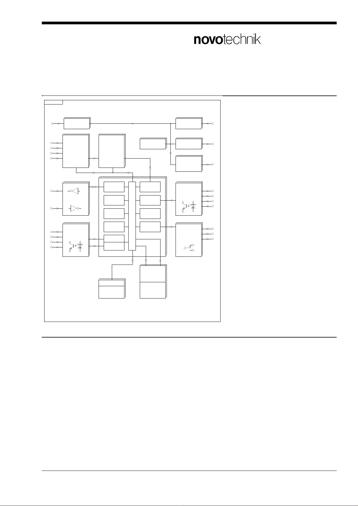
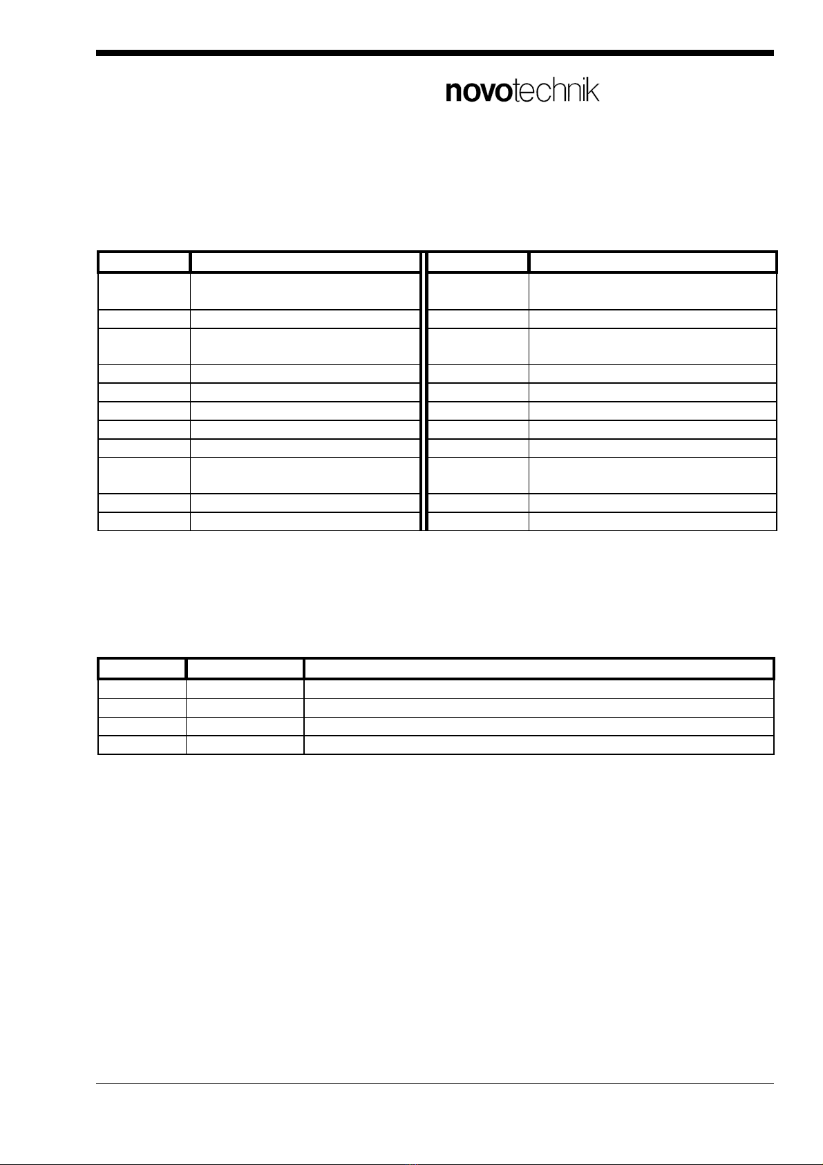
Selection possibilities of the input functions for all inputs:
display function display function
1 taring function (static)
notice the detailed description !
c BCD-inquiry
2 taring function reset d HEX-inquiry
3 storage function: display + com-
parator (Hold)
E print start, measurement value
4 storage function: comparator F display dark function
5 storage function: display G closed-circuit output function
6 programming block H, J, L print start, progr. text (16 signs)
7 SEL-key block N limit value acceptance
8 keyboard block o print start: like „E“, but continuous
9 peakdetector: positiv P print start: like „E“, but with
<CR><LF>
A peakdetector: negativ q taring function (dynamic)
b peakdetector: difference - no function
After calling up program routine [2], the control inputs can be selected by pressing the SP>-key.
The position, which is to be changed, flashes. The input functions can be changed by pressing the
-keys.
Example: display q E 9 A
input display function
IN1 q taring function (dynamic)
IN2 E print start, measurement value
IN3 9 peakdetector: positiv
IN4 A peakdetector: negativ
3.2.1 Taring function
The taring function resets the display value at an optional position and can be externally controlled.
After activation, only the deviation from the stored taring value is displayed. The taring function can
also be reset externally, if a control input is programmed for the function "taring function reset". In
the FUNC menu, the taring value can be additionally set to zero or any optional value.
a) Taring function (dynamic) Input function „q“ > New function ! <
The taring value is stored in the internal dynamic RAM. The taring value is activ until the
supply voltage is connected. After a power fail the taring value is reset to zero. It is recom-
mended to use this function because there is no limitation on storage cycles.
b) Taring function (static) Input function „1“ > Important ! <
The taring value is stored in the internal static EEPROM. Do not use this function for fre-
quently taring cycles. Use this function only for rare cycles, when it is absolutly necessary to
protect the actual taring value against power fails. At frequently storage cycles it is possible
that storage errors will affect because of the limited and unknown storage capacity of the in-

Siedle Group
Novotechnik
Messwertaufnehmer OHG
MAP300_400_en_01.doc
11
ternal EEPROM-circuit. Data failures detected with an error message (F11) are not a part of
the warranty!
3.2.2 Storage functions
The storage function can cause the freezing of the current display value and/or of the comparator
state and can also be controlled externally. Three different storage functions can be selected:
•Storage function: display + comparator (hold)
During operation, measured value changes do not have any influence on the display value and the
switching state of the limiting value comparators.
•Storage function: display
During operation, the measured value changes do not have any influence on the display value.
Monitoring of the limiting values, however, is still carried out.
•Storage function: comparator
During operation, the measured value changes only influence the display value. Monitoring of the
limiting values is interrupted and the current switching state of the comparators are frozen.
Special features with BCD- or HEX-inquiry:
With BCD- or HEX-inquiry, the storage function for display and comparators is to be actived for
each new reading of the measured value (for this, see the detailed interface description).
3.2.3 Blocking functions
•Programming block:
The programming blocking, which can be controlled externally, secures the stored data against un-
authorized or unintentional changes. During operation, the data can only be displayed, however, not
changed. If a change is attempted, an error message (E24) is also shown in the display.
•Keyboard block:
The keyboard blocking, which can be controlled externally, prevents any of the operating possibili-
ties from being carried out via the keys of the unit on the front panel. During operation, an error
message (E25) is given off if the keys are operated.
•SEL-key block:
The SEL-key blocking, which can be controlled externally, prevents any of the operating possibiili-
ties of the SEL-key on the front panel. During operation, the limiting values can therefore only be
displayed or changed. If the SEL-key is pressed, an error message (E23) is given off.
3.2.4 Peakdetector
The peak value memory, which can be controlled externally, allows for the registration of maximum,
minimum and differential values. During operation, the maximum, minimum or differential value is
stored and displayed and the limting value is supervised independently from the selected function

Siedle Group
Novotechnik
Messwertaufnehmer OHG
MAP300_400_en_01.doc
12
positive, negative or difference. Only after resetting of the activation, is the current measured value
displayed and the stored peak value erased.
3.2.5 BCD- or HEX-inquiry
For further processing of the displayed value in an SPC, it can also be output in BCD- or HEX- for-
mat via the 4 opto-isolated outputs. For this, a control input must be programmed for the „storage
function: display + comparator“ and another must be programmed for the function
„BCD inquiry" or „HEX inquiry".
With activation of the storage input, the current displayed value and/or the comparator state is fro-
zen and the output register is loaded. Activation may only be reset after the data is accepted, since
the register is reloaded with every new activation.
From the first 0->1-edge at the input "BCD- or HEX-inquiry", the stored comparator state is applied
at the 4 outputs. After the first positive edge, the sign (0 = positive, 1 = negative) is given out. After
that, with every further positive edge, the single decimal digits (always 5 digits) are given out begin-
ning with the highest value digit. A more detailed description of the BCD/HEX interface can be tak-
en from the detailed interface description.
3.2.6 Print start
With the use of the serial RS 232 interface, it is possible to output the data via a printer by activat-
ing an input programmed as a „Print start" input.
Print start, measured value:
The measured value is output along with the unit of measure and the comparator state.
Print start, programmable texts (16 characters):
Three programmable texts with a maximum of 16 characters are output (for this, see INTERFACE
FUNCTION).
3.2.7 Display dark function
With this function, the complete display including the limiting value LED's can be darkened during
the normal function of the measuring system. All of the other functions of the measuring system are
not influenced by this darkening circuit.
3.2.8 Closed-circuit current function for outputs
The closed-circuit current function is predominantly used in technical safety systems. The switching
states of the 4 outputs are inverted with activation of the rest current function. This means that one
output is switched to the rest current state with activation, which corresponds to a voltage failure of
the unit. The rest current function acts on all 4 limiting value outputs whereby, however, only the
two relay outputs for safety-relevant circuits should be used.
3.2.9 Limit value acceptance

Siedle Group
Novotechnik
Messwertaufnehmer OHG
MAP300_400_en_01.doc
13
With activation of a logic input, which is programmed for the function „Limit value acceptance", the
current measured value is accepted as a limiting value. With this, a change of the limiting value is
carried out according to the logic input number, e.g. with logic input IN3, the limiting value SP3 is
accepted. In this way, all 4 limiting values can be stored via external control.
3.3 INTERFACE FUNCTION (RS232) [3]
series MAP 334/344/444:
With the interface function, what peripheral unit is connected to the serial interface and what data
protocol is being used is determined. If no peripheral unit is connected to the serial interface, the
setting of the interface function is of no importance.
After calling up the program routine [3], selection of the peripheral unit (A, b or C flashes) can be
carried out by pressing the -keys. After that, the desired data protocol must be selected by
pressing the SP>-key once. Using the -keys, the number of the data protocol can be changed.
device display printout with
dimension device display printout with
dimension
A000 no dimension A001 mm
A002 cm A003 m
A004 Grd A005 °
A006 mbar A007 bar
A008 Pa A009 l/h
A010 g A011 kg
A012 t A013 N
printer A014 Ncm printer A015 Nm
A016 °C A017 °F
A018 K A019 mV
A020 V A021 kV
A022 mA A023 A
A024 kA A025 mW
A026 W A027 kW
A028 VA A029 Vol %
A030 % AW A031 kN
A099 progr. value (8 signs)
Additional peripheral devices:
device display function
PC/PLC b100 distant reading or
distant control PC/ PLC
FAZ47 C200 slave indicator
FAZ 47

Siedle Group
Novotechnik
Messwertaufnehmer OHG
MAP300_400_en_01.doc
14
Programmable dimension / text:
The unit of measure with a maximum of 8 characters and the three texts with a maximum of 16
characters can be programmed via the interface. For more information about this, see the interface
description.
Data format:
The data format of the interface is permanently set and can not be changed. Please take the exact
data protocols from the detailed interface description.
9600 bps / 1 Start / 8 Databit / 2 Stopbit / No parity check
3.4 MEASURING RANGE [4]
In this program routine, the desired measuring range is programmed. The connection of the signal
source or the sensor must also be carried out according to this setting.
Measuring ranges, learning (teach-in):
With these measuring ranges, calibration is carried out with reading of two different measured val-
ues and allocated to different displayed values.
display measuring range calibration
100 potentiometer
200 / 270 0-10V DC
201 1-6V DC teach-in
220 0-20mA DC
221 4-20mA DC
Measuring ranges, not learning (standard values):
With these measuring ranges, calibration is carried out without the reading in of measured values.
For allocation of the desired display values, the unit always uses the standard values for the BEGIN
value and END value of the measuring range that was stored in the memory at the factory. Potenti-
ometers do not have a standard output and can therefore only be calibrated using the teach-in
method.
display measuring range measuring range:
BEGIN value
measuring range:
END value
calibration
300 / 370 0-10V DC 0V 10V
301 1-6V DC 1V 6V standard
320 0-20mA DC 0mA 20mA
321 4-20mA DC 4mA 20mA

Siedle Group
Novotechnik
Messwertaufnehmer OHG
MAP300_400_en_01.doc
15
3.5 CALIBRATION
Calibration of the measuring system is carried out in different ways depending on the selected type
of measuring range. It is only necessary once or after selection of a new measuring range or possi-
bly after the exchange of a potentiometric sensor.
3.5.1 Calibration of learning measuring ranges (teach-in)
With these measuring ranges, the measuring signal is applied during the calibration of sensors or a
calibrator.
Calibration routine:
For calibration, two different measured values are allocated to different displayed values. The dis-
play values are allocated by the user following automatic reading of the current measured value.
After BEGIN and END value programming is carried out, calibration is completed.
BEGIN value programming [5]
After selecting the program routine [5], the sensor to be calibrated must firstly be brought to a val-
ue or position, which is defined as the BEGIN value. To program the BEGIN value, press down the
SP>-key and additionally press the -key. After that, the current measured value is automatically
read (display 3-2-1) and the possibility to change the value is released. After that, a display value
corresponding to the current measured value must be set using the -keys.
END value programming [6]
After selecting the program routine [6], the sensor to be calibrated must firstly be brought to a val-
ue or position, which is defined as the END value. To program the END value, press down the SP>-
key and additionally press the -key. After that, the current measured value is automatically read
(display 3-2-1) and the possibility to change the value is released. After that, a display value corre-
sponding to the current measured value must be set using the -keys.
3.5.2 Calibration of not learning measuring ranges (standard values)
With these measuring ranges, the initial data of a sensor is known, however, it can not be simulated
for calibration.
Calibration routine:
To carry out calibration, the start of the measuring range and the stop of the measuring range (see
section „MEASURING RANGE") are allocated to two different display values. After BEGIN and END
value programming is carried out, calibration is completed.
Example: Measuring range 0 - 10 V DC: BEGIN value is 0 V, END value is +10 V
Measuring range 4 - 20 mA DC: BEGIN value is 4 mA, END value is 20 mA
BEGIN value programming [5]
After selecting the program routine [5], the BEGIN value must be defined. To program the
BEGIN value, press down the SP>-key and additionally press the -key. Only then is the possibility
to carry out changes released. After that, the desired display value must be set using the -keys.

Siedle Group
Novotechnik
Messwertaufnehmer OHG
MAP300_400_en_01.doc
16
END value programming [6]
After selecting the program routine [6], the END value must be defined. To program the
END value, press down the SP>-key and additionally press the -key. Only then is the possibility
to carry out changes released. After that, the desired display value must be set using the -keys.
3.6 ANALOG OUTPUT
3.6.1 ANALOG OUTPUT FUNCTION (OPTION)
The optional analog output (DA) allows for the connection of external measuring, control and re-
cording units to the measuring system. After calling up the program routine [7], the function and the
output quantity of the analogue output is shown in the measured value display.
The function (A or P) flashes and can be changed by pressing the -keys. To change the output
quantity (only possible with 0/4-20 mA), the SP>-key is to be pressed once and then the desired
value can be set using the -keys.
Functions:
Px Analog signal corresponds to the stored peak value with activated peak value memory. If
the input is not activated, the analog signal corresponds to the current measured value
(standard setting).
Ax Analog signal always corresponds to the current measured value.
Output quantities:
x5 Analog output 0 - 10 V DC
x8 Analog output 0 - 20 mA DC
x9 Analog output 4 - 20 mA DC
Important!
The analog output is a part of the analog component of the measuring system and is therefore is at
the same potential as the measuring input.
3.6.2 ANALOG OUTPUT START VALUE (OPTION) [8]
The analog start value fixes the display value, with which the analogue output should deliver a 0 %
output signal. The value can be changed using the -keys.
3.6.2 ANALOG OUTPUT STOP VALUE (OPTION) [9]
The analogue stop value fixes the display value, with which the analogue output should deliver a
100 % output signal. The value can be changed using the -keys.

Siedle Group
Novotechnik
Messwertaufnehmer OHG
MAP300_400_en_01.doc
17
4 FUNCTION MENU
With the FUNKTIONS-MENU it`s possible to programm all functions which have to be changed
more times at the normal measurement operation. This functions have to be programmed at the
first starting time after the SETUP-MENU.
MENU ACTIVATING
Press in the normal measurement operation the SEL-key for five seconds till the display shows
FUNC. With additional pressing of SEL-key the different function routines are selectable.
For break off press C-key.
FUNKTION MENU:
┌─── function display
[A] measuring rate
[b] display function
[C] decimal point
[d] taring value
[E] hysteresis value
[F] realtime-clock (option)
4.1 MEASURING RATE [A]
The measuring rate programmes the speed of measurement display and limit value control. The
number is adjustable with the -keys.
Measuring rates: 1 / 2 / 4 / 8 .... cycles per second
4.2 DISPLAY FUNCTION [b]
In this routine the the function of the dispIay with/without leading zeros and the function of the last
digit is programmable. For changing between the two modes press SP>-key, for changing the value
press -keys.
Adjustment of display with/without leading zeros: left side of display
F0 leading zeros YES F_ leading zeros NO
Adjustment of the function of the last digit (LSD): right side of display
01 display in 1-steps 1, 2, 3 ....
05 display in 5-steps 0, 5, 0 ....
10 display in 10-steps 00, 10, 20 ....

Siedle Group
Novotechnik
Messwertaufnehmer OHG
MAP300_400_en_01.doc
18
4.3 DECIMAL POINT [C]
The decimal point of the measurement display can be adjusted by pressing SP>-key on every
place. i.ex.:
-.-.-.-.-
4.4 TARING VALUE [d]
The taring value of the measurement display is adjustable over the hole measurement range by
pressing -keys. This routine is normaly used to reset the taring value to zero, when the value is
programmed on a undefined value by external logic control. The default value is 0000. The
frontside LED „taring“ is activated when the taring value is not zero.
4.5 HYSTERESIS VALUE [E]
In this routine the hysteresis value for all four limits is adjustable by pressing the -keys. A hyste-
resis value is necessary when an unstable measurement signal triggers moretimes the limit value
outputs. The default value is 0000.
4.6 TIME / DATE [F]
In this routine the the optional realtime-clock is adjustable. Time and date are additional outputed
on a measurement printout. The realtime-clock can be programmed and readed by the serial inter-
face too.
Adjust of time / date:
After calling this program routine [F], the displayed value can be switched between minute, hour,
day, month and year by the SP>-key. For value adjust use the -keys.
function minute
hour day month year
display
I
I - xx
ho - xx dA - xx
I
o - xx
YE - xx

Siedle Group
Novotechnik
Messwertaufnehmer OHG
MAP300_400_en_01.doc
19
5 LIMIT VALUES
MAP 334/344/444 MAP 332/342 MAP 330/340
The devices have four independent limit
value comparators. The function MIN-
or MAX-control is programmed by the
limit value function. For applications
with less then 4 limits the number is
programmable from 0 to 4. Standardly
the device have for all limits optocou-
pler outputs and additional relay out-
puts (two-way) for the limits 1 and 2.
The devices have two independent
limit value comparators. The func-
tion MIN- or MAX-control is pro-
grammed by the limit value function.
For applications with less then 2
limits the number is programmable
from 0 to 2. Standardly the device
have for both limits relay outputs
(two-way).
The devices have
no limit value com-
parators.
5.1 LIMIT VALUE PROGRAMMING
By pressing the SP>-key the prefered limit value is selectable (LED blinks). The function display
schows additional the limit value function of the selected number. For changing the limit value press
the SP>-key and additional the -key or -key. All limits which are programmed with the limit value
function to state „not adjustable“ are not displayed. So it`s possible that 4 limits are activ (3 controls
only in the background) but only one limit is adjustable for the user.
5.2 RELAY CONTACT OUTPUT
The two relay outputs (two-way) belong to the limit values 1 + 2.
5.3 OPTOCOUPLER OUTPUT
The four optocoupler outputs belog to the limit values 1...4. If the option realtime-clock is included
only limit values 3 and 4. This outputs are not resistant against short circuits and have an additional
diode against confusing the poles.
At BCD/HEX-value readout the actual displayed value is transfered out with this outputs 1...4 too.
Then the OUT 4 is the MSB and OUT1 the LSB. More about BCD- or HEX-interface see the de-
tailed interface manual. If the option realtime-clock is included BCD- or HEX-output is not possible.

Siedle Group
Novotechnik
Messwertaufnehmer OHG
MAP300_400_en_01.doc
20
6 INFO MENU
The INFO-MENU is not necessary for the normal operation of the device but there are additional
important functions for the documentation of device parameters and test functions available.
MENU ACTIVATING
Press in the normal measurement operation the SEL-key for five seconds till the display shows
FUNC. After that press the SP>-key to switch to display INFO. With additional pressing of SEL-key
the different function routines are selectable. For break off press C-key.
┌─── function display
│
[0.] configuration
In this routine the manufacture configuration is displayed. This configuration shows informations
about the hardware and options.
[1.] software version
This routine shows the used software-version.
[2.] serial number
This routine shows the serial number of the device.
[3.] limit value function
In this routine the limit value function, the programmed number of activated limits and the function
of the limit value adjustment range are displayed.
[4.] input function
This routine shows the input functions of the 4 logic inputs.
[5.] interface function
This routine shows the interface functions of the RS 232-interface.
[6.] measuring range
This routine shows the measuring range.
[7.] measuring rate
This routine shows the measuring rate.
[8.] display function
This routine shows the display function.
[9.] decimal point
This routine shows placement of the decimal point.
This manual suits for next models
8
Table of contents
Popular Measuring Instrument manuals by other brands

PCE Health and Fitness
PCE Health and Fitness PCE-TUM 50 instruction manual

Enel X
Enel X Waymeter Pro installation manual

Global Industrial
Global Industrial 412587 instruction manual

UEi
UEi DTH10 instruction manual

Tektronix
Tektronix P6417 instructions

Electro Industries/GaugeTech
Electro Industries/GaugeTech Nexus 1250 Installation & operation manual