SST MCS 350 User manual

Manufacturer: Special Systems and Technologies LLC
Proektiruemyj proezd 5274, build. 7, Mytischi, Moscow region,
Russia, 141008
Website: www.sst-iwarm.com
TECHNICAL CERTIFICATE
USER MANUAL
.00095.01
THERMOSTAT
MCS 350
Certicate of Conformity
TC RU С-RU.РС52.В.00080
Special Systems and Technologies LLC

2
TABLE OF CONTENTS:
Functional description . . . . . . . . . . . . . . . . . . . . . . . . . . . . . . . . . . . . . . . . . . . . . . . . . 4
Special features . . . . . . . . . . . . . . . . . . . . . . . . . . . . . . . . . . . . . . . . . . . . . . . . . . . . 4
Connect to a smartphone . . . . . . . . . . . . . . . . . . . . . . . . . . . . . . . . . . . . . . . . . . 4
Connect to a home Wi-Fi network . . . . . . . . . . . . . . . . . . . . . . . . . . . . . . . . . . 4
Controls and indication . . . . . . . . . . . . . . . . . . . . . . . . . . . . . . . . . . . . . . . . . . . . . . . . 4
Controlling and operation. . . . . . . . . . . . . . . . . . . . . . . . . . . . . . . . . . . . . . . . . . . . . . 5
Switching ON/OFF the thermostat . . . . . . . . . . . . . . . . . . . . . . . . . . . . . . . . . . . . . 5
Lock/unlock . . . . . . . . . . . . . . . . . . . . . . . . . . . . . . . . . . . . . . . . . . . . . . . . . . . . . . . . . . . 6
Main indication screen. . . . . . . . . . . . . . . . . . . . . . . . . . . . . . . . . . . . . . . . . . . . . . . . . 6
Menu contents . . . . . . . . . . . . . . . . . . . . . . . . . . . . . . . . . . . . . . . . . . . . . . . . . . . . . . . . 7
Operating mode setting . . . . . . . . . . . . . . . . . . . . . . . . . . . . . . . . . . . . . . . . . . . . . . . 8
Continual maintaining . . . . . . . . . . . . . . . . . . . . . . . . . . . . . . . . . . . . . . . . . . . . . . . . . 9
Anti-freezing . . . . . . . . . . . . . . . . . . . . . . . . . . . . . . . . . . . . . . . . . . . . . . . . . . . . . . . . . . 9
Program mode . . . . . . . . . . . . . . . . . . . . . . . . . . . . . . . . . . . . . . . . . . . . . . . . . . . . . . . . 10
Training mode . . . . . . . . . . . . . . . . . . . . . . . . . . . . . . . . . . . . . . . . . . . . . . . . . . . . . . . . . 15
Control mode setting . . . . . . . . . . . . . . . . . . . . . . . . . . . . . . . . . . . . . . . . . . . . . . . . . . 16
Time and date setting. . . . . . . . . . . . . . . . . . . . . . . . . . . . . . . . . . . . . . . . . . . . . . . . . . 18
Self-diagnostics. . . . . . . . . . . . . . . . . . . . . . . . . . . . . . . . . . . . . . . . . . . . . . . . . . . . . . . . 18
Performance monitoring the temperature sensor . . . . . . . . . . . . . . . . . . . . . . . 20
Restore factory settings . . . . . . . . . . . . . . . . . . . . . . . . . . . . . . . . . . . . . . . . . . . . . . . . 20
Installation manual for the Thermostat MCS 350 . . . . . . . . . . . . . . . . . . . . . . 21
Delivery set. . . . . . . . . . . . . . . . . . . . . . . . . . . . . . . . . . . . . . . . . . . . . . . . . . . . . . . . . . . . 21
Mounting and connection . . . . . . . . . . . . . . . . . . . . . . . . . . . . . . . . . . . . . . . . . . . . . 21
Mounting the floor temperature sensor . . . . . . . . . . . . . . . . . . . . . . . . . . . . . . . . 22
Mounting the thermostat . . . . . . . . . . . . . . . . . . . . . . . . . . . . . . . . . . . . . . . . . . . . . . 23
Installation of the thermostat . . . . . . . . . . . . . . . . . . . . . . . . . . . . . . . . . . . . . . . . . . 26
Assembling the thermostat . . . . . . . . . . . . . . . . . . . . . . . . . . . . . . . . . . . . . . . . . . . . 27
39
Passed for printing on 28.10.2015
WARRANTY CARD
Thermostat MCS 350,
Date of release
has passed acceptance tests and been certied disposable for
service
QCD stamp
Date of sale
Seller’s stamp here

38
NOTES
3
ATTENTION!
Please find the connection diagram and mounting instructions for the device in
the section "Mounting and connection" of the present manual.
At mounting the thermostat and heating system we recommend to entrust
to services of qualified specialists. Electrical connections and connection to a
power supply network must be performed by a professional electrician.
The installation instructions and the connection diagram do not supplant
professional skills of the device installer.
Defects of the device caused due to mechanical damages, improper installation
or operation with purposes and under conditions not anticipated by the
installation and operation instructions for the device, are not covered by the
manufacturer’s warranty.
PLEASE, DO CAREFULLY READ THIS MANUAL
PRIOR TO START THE INSTALLATION.
IMPORTANT!
Technical specifications . . . . . . . . . . . . . . . . . . . . . . . . . . . . . . . . . . . . . . . . . . . . . . . . 27
Transportation and storage . . . . . . . . . . . . . . . . . . . . . . . . . . . . . . . . . . . . . . . . . . . . 28
Safety measures . . . . . . . . . . . . . . . . . . . . . . . . . . . . . . . . . . . . . . . . . . . . . . . . . . . . . . . . 28
Warranty obligations . . . . . . . . . . . . . . . . . . . . . . . . . . . . . . . . . . . . . . . . . . . . . . . . . . . 29
Warranty card. . . . . . . . . . . . . . . . . . . . . . . . . . . . . . . . . . . . . . . . . . . . . . . . . . . . . . . . . . . 30

4
FUNCTIONAL DESCRIPTION
The Thermostat MCS 350 is a unique device that makes your life
comfortable and convenient. The MCS 350 is designed to control
electrical heating systems in premises (heating mats, film heaters or
heatingcable sections).The thermostat maintains a comforttemperature
of the heated surface and ensures rational power consumption. The
thermostat provides the control using two temperature sensors: a floor
sensor and an air one, simultaneously as well as individually (included
in the delivery set).
The Thermostat enables to control the water warm floors when using a
thermal head of the normally closed type controlled with 220 V.
The remote control of the floor heating is carried out via Wi-Fi network
directly from a smartphone by the MCS 350 application or via a home
Wi-Fi router.
You can add up to 32 MCS 350 thermostats into your home network.
The Thermostat MCS 350 is mounted onto a wall in close proximity
to installation wires of a heating cable (section "Mounting the floor
temperature sensor" Fig. 19).
37
NOTES

36
Customer care: (495) 728-80-80, info@sst-iwarm.com
Proektiruemyj proezd 5274, build. 7, Mytischi, Moscow region,
Russia, 141008,
Please nd addresses and telephones of service centers in other
regions on the web site www.sst-iwarm.com
5
Replacing thermostats of other series and manufacturers in use with
the Thermostat MCS 350 is permitted. At that, you may choose the
parameters of the temperature sensors in use from the proposed list in
the MCS 350 application.

6
SPECIAL FEATURES
ТThe Thermostat MCS 350 enables to control your warm floor both
directly by the device touch screen and by using the MCS 350
application installed on a smartphone.
The thermostat is connected to a smartphone via Wi-Fi.
The MCS 350 may operate in two main modes: "AP" (Access Point) and
"STA" (connection to a station).
The Wi-Fi network of the thermostat is activated when the lock mode is
enabled (page 6). Immediately after enabling the lock mode, the
thermostat activates the Wi-Fi network for one of the modes that will be
shown on the display (AP or SA). When enabling the lock, there is a new
connection to the Wi-Fi network every time.
To switch between the modes "AP" and "STA", hold the button "Cancel"
in the lock mode.
MODE "АР" (Access Point) "АР" Indication
The thermostat act as an access point. It creates the Wi-Fi network:
SSID: MAC-address of the thermostat, e.g. В3:45:Е2:67:85:А0
Password: 1234567890
35
WARRANTY OBLIGATIONS
The manufacturer guarantees compliance of the thermostat quality to
the requirements of the technical specificationsTU 3428-341-33006874-
2015 on condition that the transport regulations and installation and
operation instructions are followed.
Warranty period — 5 years from the date of sale.
During the warranty period the Buyer has the right for repair or
replacement of the product when detecting failures occurred through
the manufacturer's fault and on condition that the installation and
operation instructions are followed.
The warranty obligations do not cover thermostats with mechanical
damages as well as with defects due to improper installation, connec-
tion and operation of this device.
Providing the completed warranty card indicating the name of the
product and the seller's stamp is obligatory for fulfillment of warranty
obligations.
Claims
If defects are detected during the warranty service period of the device,
the Buyer is to immediately contact the service center of the manufac-
turer or its authorized representatives in regions.

34
TRANSPORTATION AND STORAGE
The thermostat is allowed to be transported by all means of transport in
accordance with rules valid for a particular transport mode with
observance of the transport conditions provided for the Group C
according to GOST 23216-78.
The thermostat must be stored with observance of the storage
conditions 2 (C) according to GOST 15150-69.
SAFETY MEASURES
The thermostat corresponds to the technical regulations of the Customs
Union TR TS 004/2011 "On Safety of Low-Voltage Equipment", TR TS
020/2011 "Electromagnetic compatibility of technical equipment".
Connection of the thermostat must be performed by a qualified
electrician.
All the works related to mounting and connection of the device shall be
performed when the power supply voltage is de-energized.
For mounting the thermostat use only a plastic junction box.
When detecting a failure, you need to contact the dealer center or the
seller.
7
MODE "STA" (Station mode) "SA" Indication
The thermostat is connected to a Wi-Fi network specified in settings
(Fig. 1).
When there are no settings (by default), the thermostat is connected to
the network:
SSID: MCS350_default
Password: 1234567890.
CONNECT TO A SMARTPHONE
For easy adjustment of the thermostat, it needs to be connected to your
smartphone via the Wi-Fi network. For this purpose it requires to:
1. Download the MCS 350 application to a smartphone.
2. Switch the thermostat to the "AP" mode by pressing the button
"CANCEL" in the lock mode (the AP symbols shall be shown on the
display).
3. In the network configuration choose the Wi-Fi network which
corresponds to a MAC-address of the thermostat. The MAC-address of
the thermostat is specified on the inner side of the top cover (device
with a display), in the technical certificate and on the packing box.
4. Connect to this network with the password 1234567890
5. Manage the device settings easily!
8
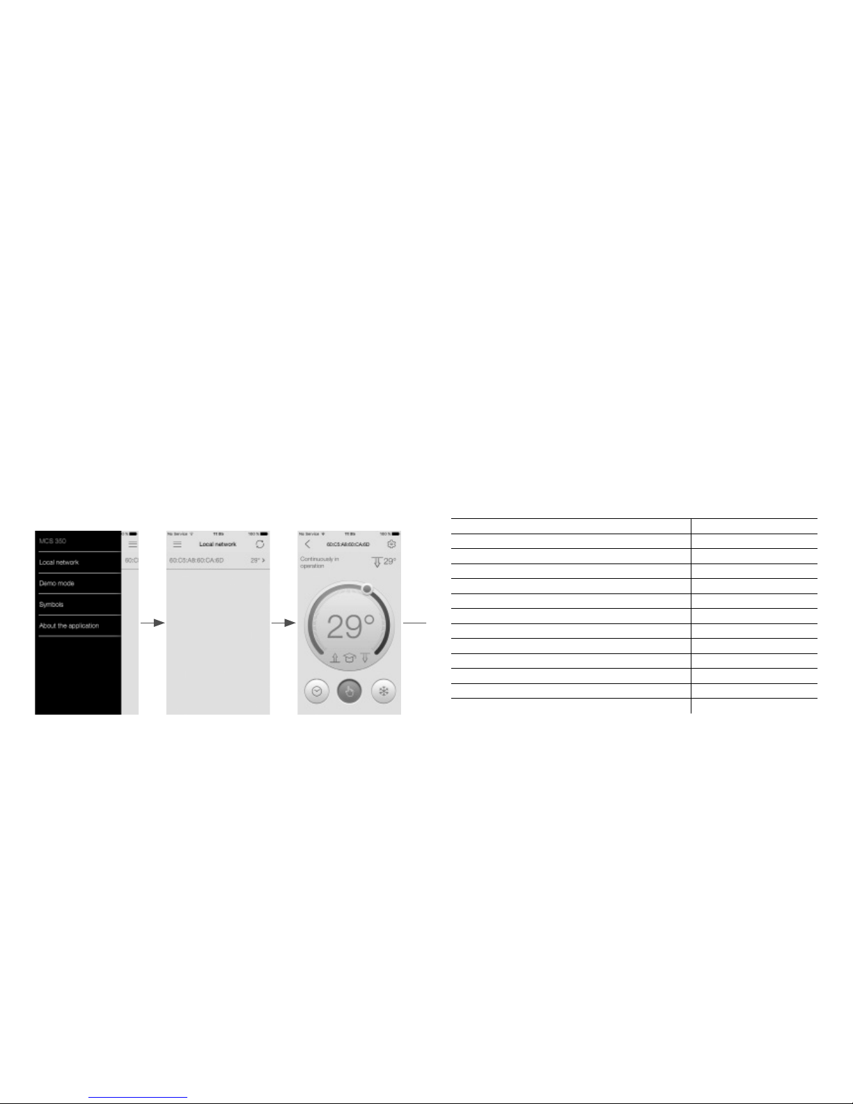
CONNECT TO A HOME WIFI NETWORK
1. Make sure that a smartphone is connected to the Wi-Fi network of the
thermostat.
2. Launch the MCS 350 application.
3. Enter the Menu —> Local network —> Thermostat —> Settings —>
Wi-Fi connection.
33
Assembling the thermostat:
Gently mount the front cover of the thermostat onto the upper hooks
of the back cover and push it at an angle until both clamps click,
ensuring that it fits tightly to the back cover of the device installed on
a wall.
TECHNICAL SPECIFICATIONS
THERMOSTAT MCS 350
Supply voltage 220 V
Maximum load current 16 А (3,5 kW)
Power consumption 450 mW
Weight 150 g
Dimensions 90×90×41 mm
Protection rating IP21
Protection class II
Floor temperature sensor (TST02) NTC 6,8 kOhm
Length of the sensor installation wire 2 m
Permissible ambient temperature from +5 °С to +40 °C
Permissible related air humidity 80 %
Temperature control limits from +5 °С to +45 °C
Service life period not less than 10 years

32
Installing the thermostat
Disassembling the thermostat.
1. Remove the front cover. For this purpose, by using a thin flat-blade
screwdriver, gently and in turn, press the fixing clamps placed at the
bottom of the front cover of the thermostat at that pulling it out
(Fig.22a).
2. Remove the cover (Fig. 22b).
3. Mount the back cover of the thermostat into a junction box and fix it
by two screws as minimum.
Fig. 22a Fig. 22b
front
cover
back
cover
9
4. Enter a name of the Wi-Fi home network or choose it from the list by
pushing "SSID select".
5. Enter a password of the home network.
6. Push the "Connect".
7. Make all these steps with all the thermostats which need to be
connected to the home network. The home Wi-Fi network may
connect simultaneously up to 32 thermostats.

10
CONTROLS AND INDICATION
To display information and manage operating modes, the MCS 350 uses
the liquid crystal touch display with the functional control buttons.
The device is managed by the control buttons:
1. "–" — decrease the temperature value;
2. "MODE/OK" — set the operating modes and temperature limits;
3. " " — switch ON/OFF the thermostat, switching the indication
modes of the main screen;
4. "PROG./ESC" — enter the program mode;
5. "+" — increase the temperature value.
4
3
5
2
1
Fig. 1
31
If you use the 3-wire electric network (with a separate ground
conductor), a ground conductor and the heating section or mat shield
are connected to each other by using the external screw terminal
(included in the delivery set) (Fig. 21).
Fig. 20
Fig. 21
single-core heating cable
neutraltemperature
sensor 220 VAC
phase
double-core heating cable
neutraltemperature
sensor 220 VAC
phase
double-core heating cable
neutraltemperature
sensor 220 VAC
phase
external
screw
terminal
network ground
conductor
single-core heating cable
neutraltemperature
sensor 220 VAC
phase
external
screw
terminal
network ground
conductor

30
Lead power wires, installation wires of the heating mat or section and
the installation wire of the floor temperature sensor to it.
Apply voltage to the power wire. By using the indicator, identify phase
and neutral wires and mark them.
All the wires are connected to terminal contacts of the device with a
screw connection.
The temperature sensor is connected to the terminals 1and 2, (at that,
the polarity is not important). Supply voltage (alternating 220 V) is
applied to the terminals 5and 6, while the phase (identified by the
indicator) – to the terminal 6, and the neutral – to the terminal 5.
The heating section or mat outlets are connected to the thermostat in the
following way: 1) a white or brown wire is connected to the terminal 3;
2) a blue (light blue) wire is connected to the terminal 4; 3) the shielding
braid outlet (yellow-green wire), as follows:
If you use the 2-wire electric network (no ground conductor), the
heating section shield is connected to the neutral conductor (N) of the
power network, to the terminal 5 (Fig. 20).
11
CONTROLLING AND OPERATION
Switching ON/OFF the thermostat
The device is switched ON by pressing the button 3.
When the device is disconnected from the power network, time and
date shall be set again. To set current date and time, please see the
section "Time and date setting" (page 18).
Fig. 2. Time and date setting screen
Lock/unlock
To ensure the childproofing and protect from accidental key presses,
the device provides the key locking. It is switched ON automatically in
40 seconds after the last key press.
12
1. Current time
2. Training mode is ON
3. Wi-Fi signal level
4. Comfort temperature set
5. Operating mode
6. Weekday
Main indication screen
The main indication screen of the device may have two modes:
— indicating the current time (Fig. 3a)
— indicating the surface and air current temperature (Fig. 3b)
The preset floor temperature is shown in large figures.
For switching between time and temperature indication, use the
button3. Single pressing switches the indication screen.
To unlock the device, press simultaneously "+" and "–" keys and hold
within 3 seconds at least. After that, the device is unlocked. Simulta-
neously pressing "+" and "–" locks the device immediately without
waiting 40 seconds.
The Wi-Fi network is automatically activated when locking is enabled.
29
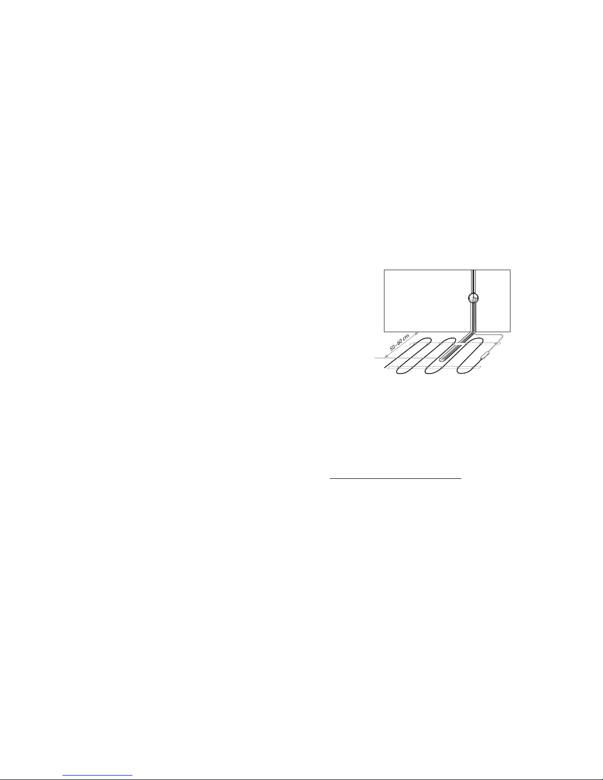
Fig. 19
Another tube end with the installation wire of the temperature sensor
inside is laid into the prepared floor groove (chase) and led to the
thermostat installation place or to a junction box.
Unused excesses of the tube and the installation wire are cut off, as
applicable.
Mounting the thermostat
Preparing the electrical connections
Install a mounting or a junction box (if used).

28
De-energize the wiring prior to start connecting the thermostat or its
disconnecting for inspection or replacement. Electrical connections and
connecting the device to power supply network must be performed by a
qualied electrician.
Mounting the floor temperature sensor
The temperature sensor is mounted into the corrugated plastic tube.
The tube end is closed with the sealed blank plug to prevent the tile
fixing or cement mixture from getting inside during the warm floor
installation.
The corrugated tube with the sensor inside is mounted at the level of
the heating cable, between its loops, within equal distances from them
(Fig. 19).
Mounting the floor temperature sensor is performed at the stage of installation of
a heating mat, section or film. The thermostat is mounted at the end of the warm
floor installation.
IMPORTANT!
IMPORTANT!
13
Fig. 3a
Fig. 3. Main indication screen
Fig. 3b
Menu contents
The thermostat provides three basic operating modes:
— Continual maintaining;
— Program mode;
— Anti-freezing.
1
2
3
5
4
7
6
8
9
10
7. Floor temperature sensor enabled
8. Air temperature sensor enabled
9. Current air temperature
10. Current floor temperature

14
The thermostat enables to control heating systems by using two
sensors — the floor temperature sensor and the air temperature one.
There are three basic control modes:
— only by floor temperature;
— only by air temperature;
— by floor temperature with a limit on air temperature;
Operating mode setting
To set the operating mode required, press and hold the button "MODE"
within 4 seconds. At that, the display shows the main screen (in the
continual maintaining mode – Fig. 4a, in the anti-freezing mode –
Fig.4b, in the program mode – Fig. 4c). The current mode icon will be
blinking.
By using the buttons "+" and "–" choose the mode required and press
the button "MODE" to confirm the choice. At that, the display shows the
main screen.
27
INSTALLATION MANUAL FOR THERMOSTAT MCS 350
Delivery set
1. Thermostat MCS 350
2. Floor temperature sensor with the installation wire (2 m length)
3. External screw terminal for the ground line
4. Technical certificate. User manual
5. Packing box
Mounting and connection
The list of instruments and materials required for mounting:
1. Corrugated plastic tube not less than 16 mm diameter (the
length depends on the thermostat installation place)
2. Standard plastic junction box
3. Flat-blade screwdriver
4. Supply voltage phase indicator

26
Fig. 17. Heating sensor break Fig. 18 . Heating sensor short circuiting
Performance monitoring the temperature sensor
The thermostat continually monitors the performance of the tempera-
ture sensor. When it breaks down (failure or short circuiting of installa-
tion wires), the display will show the fault information (Fig.17, 18).
You should contact the dealer to perform repairs or replace the
temperature sensor.
Restore factory settings
The thermostat provides an ability to restore factory settings. For this
purpose, you need to press and hold the button "MODE" within
8 seconds. After a sound signal, the device goes back to the main
indication screen.
15
Fig. 4a Fig. 4b Fig. 4c
Continual maintaining
This mode (Fig. 4a) is used when it needs to maintain the temperature set.
To set the temperature, press the button "+" or "–". The temperature
value will be blinking. The temperature can be set in the range +12 ...
+45 °С.
Set the desired temperature and press the button "OK" to confirm.
Anti-freezing
The Thermostat MCS 350 in the "anti-freezing" mode (Fig. 4b) may
decrease the temperature in the heated premises over a long period to
the level preventing the freezing and thus saving electric energy.
16
This mode can be applied when no need for the comfort heating, e.g.
when you are away from home.
In this mode the maintaining temperature comes down to the anti-
freezing temperature.
The anti-freezing mode is similar to the constant maintaining mode, but
the temperature can be set in the range +5 ... +12 °С.
The temperature settings are different for these two modes.
Program mode
This mode (Fig. 4b) is an effective means for saving electric energy when
no need for the continual heating and the comfort temperature is only
required for specified time periods.
The program mode is event-driven, i.e. the thermostat has four events
which time you may set accurate within 10 minutes.
— Waking up;
— Leaving home;
— Coming home;
— Sleeping.
25
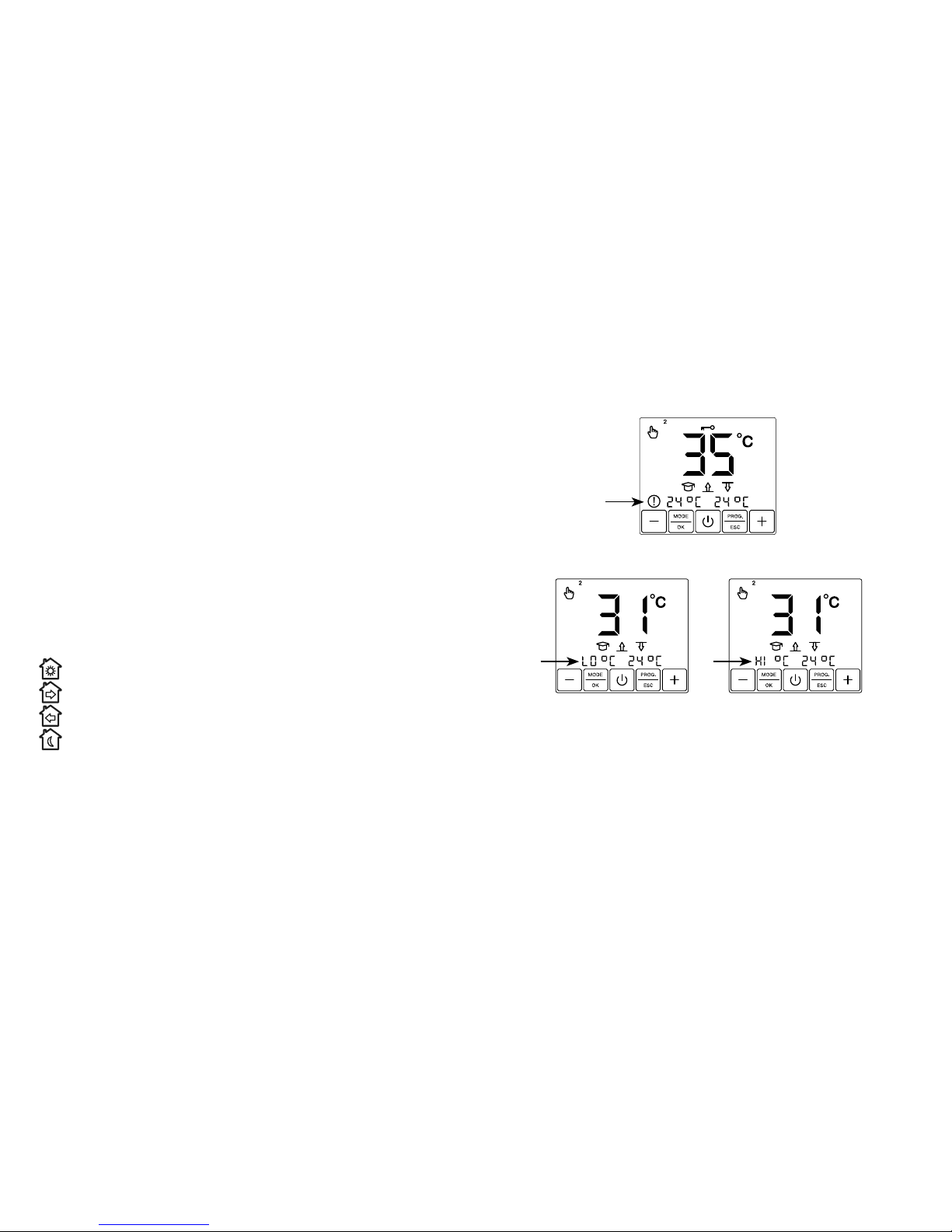
Fig. 16a. Low temperature Fig. 16b. High temperature
Fig. 15. No heating up
If the floor temperature drops down below +5 °С, or rises above
+45°С, the display will show the information about it (Fig. 16a, 16b).

24
Fig. 13. Date settings Fig. 14. Time settings
Time and date setting
Press the button "PROG." and hold it within 8 seconds. At that, the
thermostat will go into the time and date settings mode. The date
value starts blinking. Choose the current year, month and date by
using the buttons "+" and "–" (Fig. 13). A weekday is set automatically.
Press "OK". You enter the current time settings. The time value starts
blinking (Fig. 14). Set the time required and press "OK".
Self-diagnostics
The thermostat continually controls the operation of a heating
system. When the system is not able to heat up the surface to the
temperature set within 4 hours, the display will shows the appropriate
information (Fig. 15).
17
Fig. 5. Menu "programming the device"
For each event you can define its time and maintaining temperature
that is set in the range +5… +45°С for every event.
The thermostat has a training mode. In analyzing the floor temperature,
the air one or both temperatures together, the MCS 350 calculates
when the system switches ON in order to reach the set comfort
temperature by the time you defined.
The training mode can be deactivated (see page 15).
To program the thermostat press and hold the button "PROG." within
4seconds. At that, the display shows the main screen (Fig. 5).
By using the buttons "+", "–" and "OK", set the time for every event and
the maintaining temperature desired.
18
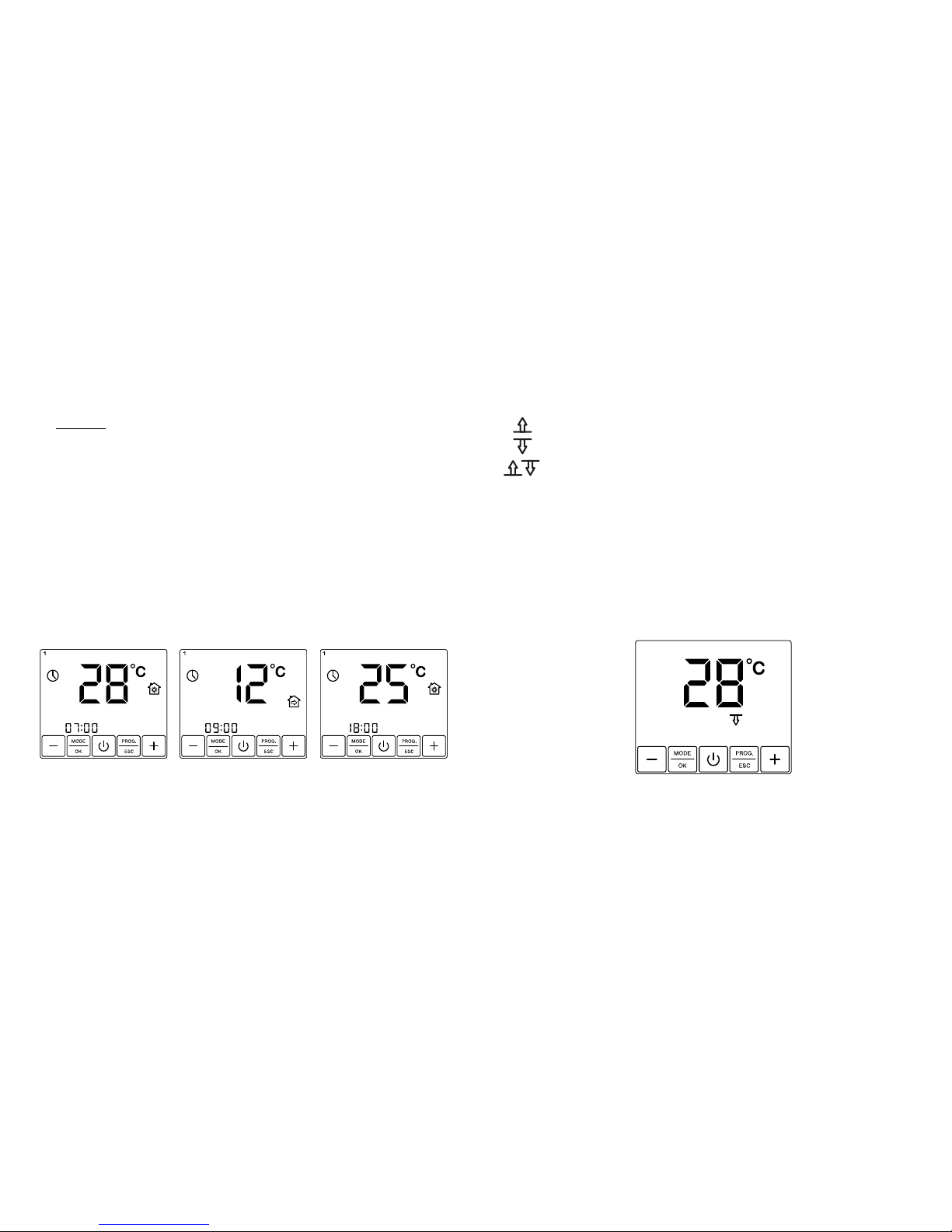
Fig. 6 Fig. 7 Fig. 8
Example:
You need to set the +28 °С temperature period for Monday-Friday from
7:00 till 9:00 in the morning, temperatures +25 °С from 18:00 till 22:00 in
the evening and also for Saturday-Sunday from 10:00 till 22:00. At all
other times the temperature +12 °С shall be maintained.
Press and hold the button "PROG." within 4 seconds. At that, the display
shows the main screen. Fig. 5.
Press the button "OK". The display will show the time and temperature
screen of the first event (Fig. 6). The time value will be blinking. By
using the buttons "+" and "–" set the time 07:00 and press "OK". The
temperature value will be blinking. Set the temperature value 28 °С by
using the buttons "+" and "–" and press "OK".
23
— only by floor temperature;
— only by air temperature;
— by floor temperature with a limit on air temperature;
After the desired control mode is chosen, confirm it by pressing "
OK
"
(Note: the button "ESC" is not active in this mode).
When setting the control mode by using both sensors, you will enter the
air temperature limit screen (Fig. 12). It needs to set the maximum air
temperature by using the buttons "+" and "–" and press "
OK
".
The thermostat controls the air temperature and switches OFF the heating
in case of exceeding the maximum value set.
Fig. 12. Maximum air temperature settings

22
By using the buttons "+" and "–", set the control mode desired. At that,
the active icon will be blinking. An inactive one will not light.
The button "–" — switches ON/OFF the training mode
The button "+" — switches the control modes.
Fig. 11. Control mode settings
Control mode setting
To choose the control mode, press and hold "MODE" within 8 seconds.
You will enter the control mode settings screen (Fig. 11). At that, the
mode icons will be blinking.
19
You enter the settings screen for the second event (Fig. 7). By using the
buttons "+" and "–", set the time 09:00 and press "OK".
Set the temperature value 12 °C by using the buttons "+" and "–" and
press "OK".
Then, in the settings screen for the third event (Fig. 8) by using the
buttons "+" and "–", set the time 18:00 and press "OK".
Set the temperature value 25 °C by using the buttons "+" and "–" and
press "OK".
In the settings screen for the fourth event (Fig. 9) by using the buttons
"+" and "–", set the time 22:00 and press "OK".
Set the temperature value 12 °C by using the buttons "+" and "–" and
press "OK".
After pressing "OK", you will enter the settings screen for event time of
Tuesday, that will be indicated with the icon "2" at the top of the screen
and which will light on the display (Fig. 10).
In the same manner, set the event time and the temperature level for
every weekday till Saturday. The display will show the icon "SAT"
(Saturday).
Set the time of the first event 18:00 by using the buttons "+" and "–"
and press "OK".
Set the temperature value 25 °C by using the buttons "+" and "–" and
press "OK".

20
After entering the settings screen for the second event of Saturday, do
not change the time and go to settings of the temperature value by
pressing "OK". Set the temperature value 25 °С by using the buttons "+"
and "–" and press "OK". In the same manner, do not change the time of
the third event, but set its temperature equal to 25 °С.
In the settings screen for the fourth event of Saturday, set the time 22:00
by using the buttons "+" and "–" and press "OK". Set the temperature
value 12 °С and press "OK".
In the same way, set the time of events and the temperature level for
Sunday.
After pressing "OK", you will enter the main menu. To activate the
program, it needs to enable the program mode (see the section
"Operating mode setting" page 8).
Fig. 9 Fig. 10
21
The default time and maintaining temperature values are specified in
the Table 1.
Training mode
When operating the program mode, the thermostat has an ability to
analyze temperature specifics of premises, switch ON the heating in
advance and reach the temperature you set exactly to the appointed
time. The training mode can be disabled (see the section "Control mode
setting" page 16). In this case the thermostat switches ON the heating
exactly at the stated time.
EVENT
WEEKDAY
Monday – Friday time 7:00 8:00 19:00 22:00
temperature level 28 12 28 12
Saturday – Sunday time 7:00 8:00 19:00 22:00
temperature level 28 12 28 12
Табл. 1
Table of contents
Other SST Thermostat manuals


