VLM HP-2F User manual

- 2 -
VLM GmbH
Heideblümchenweg 50
D-33689 Bielefeld
Fon +49 5205 87 963-0
Fax +49 5205 87 963-50
We have pleasure if you are calling us:
Hans-Ulrich Vogler, Fon +49 5205 87 963-11
Managing Director e-mail hu.vogler@vlmgmbh.de
Sales & marketing
Technical Support
Alexander Schubert Fon +49 5205 87 963-14
Customer management e-mail a.schubert@vlmgmbh.de
Josef Schubert Fon +49 5205 87 963-20
Managing Director e-mail j.schubert@vlmgmbh.de
Production & Technical
Support
We are available at any time :
www.vlmgmbh.de www.vlm-laborshop.de

- 3 -
Content
1. Generalities 4
1.1 Purposeof thedocument 4
1.2 General indications
1.3 Operators 4
1.4 4 User´s assessment 4
1.5 5Copyright 4
4
2. Basic safety instructions 5
2.1 Safetysymbols 5
2.2 Obligationsandliability 6
2.3 3Dangersrelatedtotheuseofmetalblockthermostats 6
2.4 4Claimsand liability 6
2.5 5 Correct use 7
2.6 Incorrectuse 7
2.7 Organisationalmeasures 7
2.8 Informalsafetymeasures 7
2.9 Particularpointsofdanger 7
2.10 Modificationstotheunit 8
2.11 1Cleaningoftheunitandwastedisposal 8
2.12 Firefighting 8
2.13 Safetyinstructionsrelatedtotheuseoftheunit 9
3. Transportation /Packaging 10
3.1 Acceptanceof parcelsandunpacking 10
3.2 Forwardingorsendingback 10
4. Installationofthe device 11
4.1 Spacerequirements 11
4.2 Set-upandconnection 11
5. Description 12
5.1 Totalview 12
5.2 Funktionofthe Microprocessor-Controller(PID) 13
5.3 BasicAdvices 13
5.4 TheFunctionKeysofthemicroprocessor-controller(PID) 14
5.5 OperatingtheMicroprocessor-Controller(PID) 15
5.5.1 Permanentworkingmode 15
5.5.2 TimerWorkingmode 15
5.5.3 mpfunction 15
5.5.4
Briefinstruction:operatingofthemicroprocessorcontroller(PID) 16
5.6 6Calibrationofthecontroller 16
5.6.1 PrincipleoftheCalibration 16
5.6.2 librationprocedurestepbystep 16
5.7 Safety devices 17
5.8 8Conformity 17
5.9 9 Normalsupplies 17
5.10 Productslines-interchangeableheatingblocks 18
5.11 Technicaldata 19
6. Puttingintooperation/ Operation 19
6.1Samplevessels 19
7. Maintenanceand repairs 20
7.1 1Replacementof afuse 20
7.2 2Decontamination 20
7.3 Sparepartlist 20
8. Malfunction displays 21
8.1 1Diagnosisalarms Microprocessor-Controller 21
8.2 Malfunctiondisplays 21
9. Appendix 22/23

- 4 -
1. Generalities
1.1 Purpose of the document
The purpose of this operating manual is to familiarise the user of the VLM Metal Block Ther-
mostat with:
function,
operation
safety instructions
maintenance of the unit
diagnostic of malfunction and trouble shooting
This manual must always be within reach of the user!
Read these instructions carefully before installing the unit and putting into operation!
1.2 General indications
The operation manual instructs the operator to handle this test cabinet with safety and only for the pur-
pose it is designed for. Knowledge of the relevant chapters is an imperative precondition for the safe and
correct use.
Operators are duty bound to familiarise themselves with the safety instructions and operating conditions
in order to avoid injury and damage.
Claims and liabilities will be rejected if they are due to incorrect operation and/or incorrect use.
Necessary maintenance works may only be carried out by personnel of VLM or their representatives
resp. authorized experienced persons. Otherwise all claims and liabilities will be rejected.
Our indications are based on the state of our current knowledge. Legal rules have to be observed on
own responsibility. Shown devices and details can partly be presented with options.
Subject to technical alterations.
1.3 Operators
VLM-Metal Block Thermostats may only be used by personnel trained and authorised by the
operator.
1.4 4 User´s assessment
Dear readers,
our operating manuals are regularly updated and may be downloaded from our web site
www.vlmgmbh.de. Please ask for your password to get access to this protected area.
Your suggestions for improvements will help us to provide user-friendly operating manuals.
Please inform us by e-mail (info@vlmgmbh.de) or by fax +49 5205 87 963-50.
1.5 5 Copyright
©2012 VLM GmbH, Business Unit Laboratory Technology D-
33689 Bielefeld, Heideblümchenweg 50
All rights reserved.
Reproduction, even partial, is only allowed with the authorisation by the Company.

- 5 -
2. Basic safety instructions
This operating manual contains the main instructions allowing the safe use of VLM Metal Block Thermostats.
2.1Safety symbols
The following designations and symbols are used for safety indications throughout this manual:
Fig. 1
Signification: immediate danger to life and health of persons.
Ignoring these indications will result in severe health hazards
Fig. 2:
Signification: possibly dangerous situation.
Ignoring these indications may result in slight injuries or cause material
damage
Fig. 3
Signification: important indications for the correct use of the unit.
Ignoring these indications may cause malfunctions of the unit or problems in
the vicinity of the latter

- 6 -
2.2 Obligations and liability
Please follow the instructions imparted in this manual.
For the safe and unproblematic operation of the VLM Metal Block Thermostat,
knowledge of the basic safety instructions and regulations is imperative.
This operating manual and especially the safety instructions must be respected by all
persons who work with the unit. Furthermore, all rules and regulations concerning the
prevention of accidents, which are valid at the site of use of the unit, are binding.
2.3 Dangers related to the use of metal block thermostats
VLM-Metal Block Thermostats have been designed and manufactured according to the
state of the art and to recognised safety technological rules. However, the use of the
units may cause dangers to the life and health of the user or of third persons, or damag-
es to the unit or to other property.
VLM Metalblock-Thermostats may only be used
for the purpose they were designed for
in perfect safety technologic conditions
Failures which may impair safety must be corrected immediately!
2.4 Claims and liability
Basically, our "General Sales and Delivery Conditions" (http://www.vlmgmbh.de).
Claims and liabilities toward personal and material damages will be categorically rejected if they are
due to one or more of the following causes:
incorrect use of the units
incorrect set-up, start-up, operation and maintenance of the units
operation of units with faulty safety and protective systems
ignoring the instructions of the operating manual concerning transport, storage,
set-up, start-up, operation and maintenance of the units
unauthorised constructive changes to the units
incorrect repairs
catastrophes due to the action of foreign bothes and force majeure.
As a rule, provisions and indications stated on the warranty card provided together with
the unit apply.

- 7 -
2.5 Correct use
VLM Metal Block Thermostats are temperature regulated heating devices for use in laboratories.
They are used to heat analysis samples to predefined temperatures, without using heat transfer fluids.
Keeping and following all instructions and indications from the operating manual are part of the cor-
rect use.
VLM Metal Block Thermostats may only be used by persons authorised by the operator.
Users are responsible towards third persons within the working area.
2.6 Incorrect use
Use for any other purpose as those indicated above is not authorised.
The incorrect use of the unit may generate risks.
2.7 Organisational measures
The operator will provide personal protective equipment.
2.8 Informal safety measures
Always keep this operating manual together with the unit.
Keepthegeneralandlocalregulationsforpreventionof accidentsandfor
environmental protection at hand and follow them.
Keepallsafetyandriskindicationsontheunitinlegibleconditions,renew
if necessary.
2.9 Particular points of danger
The following constitute particular points of danger:
the hot metal blocks
the emptied hot heating bathes
the surface of the thermostats in the vicinity of the hot metal block
closed test tubes or reaction vessels

- 8 -
2.10 Modifications to the unit
Donotcarryoutmodificationstotheunitnortothesettingswhichmaynotbechanged
without the manufacturer's authorisation!
Exchangepartswhicharenotinperfectconditionsatonce(e.g.mainpowercable)!
Only use original spare parts!
In case of parts purchased from other manufacturers it cannot be assured that they
will meet the requirements, nor that they have been designed and manufactured so
as to fulfil technical and safety requirements.
2.11 Cleaning of the unit and waste disposal
Only clean the unit if it is switched off and cold
Only clean variable metal blocks if they are cold
Clean stainless steel surfaces and metal blocks only with neutral laboratory
cleansing products
Useproductsandmaterialscorrectlyanddisposeofthemaccordinglyoncetheyare
used
2.12 Fire fighting
In case of fire, it is imperative to switch off the unit and to pull the main plug, as other-
wise fires caused by electricity cannot be fought effectively!
Observe fire fighting instructions at the working place!

- 9 -
2.13 Safety instructions related to the use of the unit
Make sure to follow safety instructions for laboratory work!
Follow safety instructions valid for the samples to be processed.
Read the safety sheets of hazardous reagents applied
The metal blocks are only foreseen to receive the sample containers.
No samples may be introduced directly into the holes drilled in the metal
blocks
Never touch hot surfaces of the heat block or in its vicinity! Attention:
sample containers can also be hot when taken. Use protective gloves and
adequate tools to take samples!
Avoid defervescence and risks of projections through hot sample materi-
al. Wear protective gloves and facial protection! Avoid risks of injury
through pressurized sample containers! Let closed sample container
cool down after the end of chemical disintegration!
If toxic gases or vapours may be generated or set free, work in a fume
cabinet. Make sure to respect valid safety regulations for work in fume
cabinet!
Explosive and lightly flammable materials may not be brought into the
vicinity of hot surfaces or sample containers!

- 10 -
3. Transportation / Packaging
Metalblock thermostat are packed by VLM according to their demand with largest care, wrapped usually in
air cushion foil and set in cardboard box protected strengthened with polystyrene inserts.
3.1 Acceptance of parcels and unpacking
In case of damages caused by impacts during transportation claims are made exclusively with the re-
spective forwarder, parcel service or post office. If there is any doubt about the integrity confirm the
acceptance only under the reservation of the following examination of the content.
Open the transport package and remove the filling material.
Take out the unit and accessories carefully, put all the items on a table and compare them with the
delivery note.
Please note that according to our terms of business the completeness of the consignment has to be
checked without any delay. Late claims of missing parts will be rejected.
3.2 Forwarding or sending back
Note: VLM Metalblock Thermostats are highly sensitive electronic devises. For that reason special pre-
cautions have to be met in case of forwarding or sending back :
Make sure that no filling material can enter into the device for instance through the aeriation holes in
the case. For this reason we recommend to wrap the device into paper or plastic foil. Note that oth-
erwise any costs for decontamination will be charged.
Use only a sufficient sturdy packaging material for the transport and label it outside “High
sensitive electronic equipment, handle with care”
Do not apply only plastic foam flakes as filling material. Otherwise the device could move to the walls
caused by vibrations during the transport. Take care the the device is well protected at all sides.
In accordance with the general terms of business of the company
(s. http://www.vlmgmbh.de) VLM will not take over any liability for damages caused by
unsuffcient sturdy packing or any other reasons.
Note:
The return or acceptance of metalblock-thermostats contaminated with
hazardous medical, biological, chemical or radioactive substances are
basically excluded.

- 11 -
4. Installation of the device
4.1 Space requirements
Put the metalblock-thermostat on a solid and steady floor.
Note, that a falling down unit caused severe risks to life and health.
Operation mode (Regulation) may be negatively influenced through:
strong and fast temperature fluctuations
direct exposure to sun rays
draughts
VLM-Metallblock-Thermostats are designed for normal use in laboratories.
If there are any risks to the health of the operator or third persons or the environ-
ment appropriate safety precautions have to be applied, such as putting the
thermostat into a fume cabinet, using safety hoods or sucking off of hazardous
vapours.
“Guidelines for Laboratories” and safety sheets have to be followed strictly .
4.2 Set-up and connection
Safety hood for EC-Thermostats
Set-up and connection
Set up the unit near an electric plug.
Check nominal voltage (cf. nameplate at the back of the unit); this must be the
same as the public grid voltage.
Read the operating manual before setting-up and connecting the unit.

5. Description
- 12 -
5.1 Total view
Stainless steel case
holder for convenient handling
Silicon seal / heating bath
interchangeable heating block
label “hot surfaces”
holes for fixing the safety hoods
main switch
pilot lamp “heater on”
edge protection
ventilation holes
VLM Microprocessor
Controller with timer- and rampfunction
Back of the case
The type plate showing the serial number and
the CE-mark are on the back side above the
mains socket.

- 13 -
5.2 Funktion of the Microprocessor-Controller (PID)
LED-Heater
LED- Relais K1 °C
K2
LED-Timer LED-
Ramp
Arrow key up
Arrow key down
Set-key key permanent
working mode Timer-key Ramp-key
5.3 General Advices
6 keys provide a convenient operating of the controller which works either in standard mode, the means carry-
ing out of the following basic functions
permanent working mode (unlimited heating)
timer working mode (limited heating)
Standby-Modus (heater cut off)
or the controller will be switched into the adjusting mode by pressing the “Set” key for > 3 seconds thus the
following settings can be changed
set-point value (SPP)
timer duration (t)
ramp gradient (Gr)
Please note: The change of the setting-mode and calibration is only possible in the stand-by mode.
All output relais will be cut off in the setting mode, that means a previous active regulating respectively heating
will be stopped until returning into the standard working mode.
Is a key not pressed within one minute the controller changed automatically into the standard working mode.
The return into the working mode is also possible by pressing both arrow keys simultaneously.

- 14 -
5.4 The Function Keys of the microprocessor-controller (PID)
SET-Key
actuates the setting mode by pressing the SET-Key (>3 s ). Moreover it allows the setting of new val-
ues. The setting value will appear by holding the SET-Key and can be changed by pressing the up-
or down arrow keys.
Permanent-Key
The permanent heating will be turned on or cut off by pressing the permanent key.
Timer-Key
the timer function will be turned on or cut off by pressing this key. Moreover this key allows setting of
the time hh:mm
While the timer is active (LED Timer is illuminated red ) the rest time can be read from the display by
pressing the down key.
The thermostat switch over to the stand-by mode after the set duration of the tempering elapsed.
The heater will be cut off and an acustic alarm is initiated. It can be switched off by pressing the ar-
row key “up”.
Ramp -Key
The ramp function will be switched off or on in the standard working mode. After switching over to
setting mode the key allows the adjusting of the ramp gradient (Temperature increase °C/min)
Arrow Keys
allows the up and down change of values.

- 15 -
5.5 Operating the Microprocessor-Controller (PID)
5.5.1 Permanent working mode
After switching the thermostat on the actual temperature appears in the display alternating with “End”.
The controller is in the stand-by mode.
If necessary you can change the actual value by change of the SET-Key > 3 s. You will get access to the
setting mode. “SPP” appears in the display. Hold the SET-Key pressed and adjust the desired set-point
value by the arrow keys. To return into the Stand-by mode by pressing both arrow keys simultaneously.
Press the permanent key. The controller change from the standby- into the permanent working mode. The
thermostat is heating up to the set-point value indicated in the display.
You can stop the permanent mode or stop by pressing the permanent key. The controller will return into the
stand-by mode.
If you have selected the permanent mode during the heating up phase in order to temper the samples for a
limited time you can change over to the timer mode by pressing the timer-key.
Besides you can activate the ramp function, for instance to approach the set-point value smoothly in order
to avoid any exothermal of digestion reactions.
5.5.2 Timer Working mode
If you want to temper your samples for a limited duration you can activate the timer function by pressing the
timer key. The timer LED is illuminated red in order to indicate the limited heating.
Please note: The timer function is starting when the set-point temperature has been reached.
You can stop or cut off the timer function by pressing the timer key for more than 3 s. The controllers returns
to the stand-by mode automatically. Please note that the beeper will not be actuated.
You can read the elapsed time of the timer from the display by pressing the “Down” arrow key.
After passing the timer duration an beeping sound will be initiated. The timer LED distinguished. The display
shows alternating “End” and the actual temperature. The beeper can be switched off by pressing the “UP”
key.
You can adjust the time (max. 99h 99 min) by pressing the SET-key > 3 s. “SPP”appears in the display.
Press the timer key. “t” appears in the display. Hold the SET key pressed and adjust the time by the arrow
keys.
5.5.3 mp function
You can activate or deactivate the ramp function at any time by pressing the Ramp key thus the correspond-
ing LED is on or respectively out. This feature allows you to reduce the power of the heating up period.
After starting the ramp function the controller measures the actual temperature and increases this value by
the setting the ramp gradient °C/ min. This is the new intermediate set-point value, valid for only one
minute. After this minute this value will be increased until the set-point values is reached. Afterwards the
set-point value will be hold constant.
You can adjust the ramp gradient by pressing the SET-key > 3 s . So you get access to the setting mode In
the display appears “SPP”. Press the ramp key. “Gr” appears in the display. Hold the SET-key pressed in
order to change the ramp gradient °C/min.

- 16 -
8
5.5.4 Brief instruction : operating of the microprocessor controller (PID)
Please note: Before changing the setting switch off the regulating by pressing the permanent key
After pressing the SET
key >3 s, press the key Display zeigt Change of Adjusting: Hold SET Key
pressed, the press
Set SSP Set-point value Temperature °C
Timer t duration of tempering hh:min
Ramp Gr Ramp °C/min
5.6 Calibration of the Controller
5.61 Principle of the calibration
Make sure that there is no draft which would disturb the high sensitive measurement. Use an electronic tem-
perature measuring device with a connected immersion sensor Ø 4,0 mm. Insert the sensor into the hole ( 4.1
mm Ø ) in the center of the heating block. After entering the calibration mode the thermostat will be heated to
two preset calibration temperatures:
max. working Temp.
Cal. temp. A
Cal. temp. B
130°C
40°C
130°C
210°C
60°C
170°C
When the temperature at the calibration temperature has been stabilized the thermostat is beeping.
Now adjust the displayed temperature to the temperature measured by the external thermometer.
5.6.2 libration step by step
●Switch the metalblock thermostat on
●make sure that neither the regulating of the heating is working, nor the timer function is on.
●Press the arrow keys for ca. 4 sec until “A” appears in the display
●Press the SET-key as long as all figures of the code “0000” appear.
●The thermostat is now heating up to the set point A for calibration (pls. see table)
●Insert the immersion sensor into the reference hole in the block
●When the block is beeping adjust the temperature figure by figure according to the temperature meas-
ured by the external device and confirm each individual value by pressing the set key.
●After this procedure the thermostat is heating up to the second calibration value B.
●When the temperature has been stabilized the thermostat is beeping. Proceed as already described.
●Adjust the temperature to the desired set point by the up and down arrow keys
●Press the permanent key so the thermostat is precisely running in the working mode

- 17 -
5.7 Safety devices
Safety element
responds when
Signal
Assistance
Overheating protection
Heating block temperature
exceeds the maximum ad-
justable set-point of
130/210°C by more than
20°C
see chapter “Malfunction”
Switch off unit.
Failure corrective action only
through authorised person
or manufacturer
Unit fuse
electric failure occurs
No unit functions
Failure corrective action
through authorised person
or manufacturer, replace
fuse
Controller fuse
electric failure of the control-
ler
No unit functions
Failure corrective action
through authorised person
or manufacturer, replace
fuse
5.8 8 Conformity
Model
Metalblock-Thermostats
HP-Thermostat
Type HP-1V... Type HP-2V... Type HP-1F... Type HP-2F...
EC-Thermostat
Type EC-1V... Type EC-2V...
BIO-Thermostat
Type BIO-1V... Type BIO-2V... Type BIO-1F... Type BIO-2F...
LS-Thermostat
Type LS-1V... Type LS-2V...
QS-Thermostat
Type QS-1V... Type QS-1F...
Guidelines or
designation of standards
Laboratory units to heat materials
Standards
DIN EN 61010-1 (VDE 0411 Part1)
DIN EN 61010-2-010 (VDE
5.9 9 Normal supplies
Metalblock-Thermostat
Mains cable
Spare fuses
interchangeable heating blocks with holders if ordered
operating manual
Special accessories:
Polycarbonate-covers
Safety hoods made of polycarbonate

- 18 -
5.10 Products lines - interchangeable heating blocks
HP-Thermostats 130°C/210°C
BIO-Thermostats 130°C
EC-Thermostats 130°C/210°C
LS-Thermostats 130°C
QS-Thermostats 130°C /210 °C
Type HB-HP1
L/W/H 139 x 98 x 75 mm
24 test-tubes Ø 16 mm
Type HB-BIO1
L/W/H 139 x 98 x 46 mm
38 microcentr.tubes 1,5 ml
Type HB-EC1
L/W/H 148 x107 x75 mm
24 test-tubes Ø 16 mm
Typ HB-LS1H
L/W/H 148 x 53 x 46 mm
24 microcentr.tubes 1,5 ml
Type HB-QS
L/W/H 92x92 x 75/46 mm
16 testubes 16 mm
24 microcentrif. tubes 1,5//2,0 ml
Type HB-HP2
L/W/H 198 x 139 x 75 mm
48 test-tubes Ø 16 mm
HB-BIO2
L/W/H 198 x 139 x 46 mm
96 microcentr.tubes 1,5 ml
Type HB-EC2
L/W/H 214 x 148 x75 mm
48 test-tubes Ø 16 mm
Type HB-LS1
L/W/H 148 x 107 x 46 mm
48 microcentr.tubes 1,5 ml
Type HB-LS2
L/W/H 214 x 148 x 46 mm
96 microcentr.tubes 1,5 ml

- 19 -
5.11 Technical data
Thermostat
Type
Power rat-
ing Watt
Case Dimen-
sions
LxWxH (mm)
Unit fuse in the
mains cable
Weight
ca. Kg
Dimensions
heating bath
LxWxT (mm)
Heating blocks capacity
HP-1V
300
382 x 212 x 140
T 4,0 A
6
140 x 99 x 75
1 HB-HP1
HP-2V
600
440 x 253 x 140
T 6,3 A
8
198 x 140 x 75
2 HB-HP1 oder 1 HB-HP-2
HP-1F
300
382 x 212 x 140
T 4,0 A
6
-
permanently installed
HP-2F
600
440 x 253 x 140
T 6,3 A
8
-
permanently installed
EC-1V
300
382 x 212 x 140
T 4,0 A
6
148 x 107 x 75
1 HB-EC1
EC-2V
600
440 x 253 x 140
T 6,3 A
8
214 x 107 x 75
2 HB-EC1 oder 1 HB-EC2
BIO-1V
300
335 x 193 140
T 4,0 A
5
140 x 99 x 46
1 HB-BIO1
BIO-2V
600
395 x 233 140
T 6,3 A
7
198 x 140 x 46
2 HB-BIO1 oder 1 HB-BIO2
BIO-1F
300
335 x 193 140
T 4,0 A
5
-
permanently installed
BIO-2F
600
395 x 233 140
T 6,3 A
7
-
permanently installed
LS-1V
300
335 x 193 140
T 4,0 A
5
148 x 107 x 60
1 HB-LS1 or 2 HB-LS1H
LS-2V
600
395 x 233 140
T 6,3 A
7
214 x 107 x 60
1 HB-LS2 or 2 HB-LS1 oder 4
HB-LS1H
QS-1V
91 x 91 x 65
1 HB-QS
QS-1F
Technical modifications reserved!
Voltage
230 V/50,60 Hz
Max. Set-points acc. to units:
HP, EC, QS-Thermostats
130°C oder 210°C
BIO, LS-Thermostats
130°C
Protective system acc. to IEC 529
IP 20
EMV-indications concerning fail-
ure classes
EN 50081-1
EN 50082-2
Length of Mains cable
2m
Controller fuse
T 2,0 A
6. Putting into operation / Operation
6.1 Sample vessels
Note that the diameter of the used test-tubes is less smaller than the diameter of the hole
thus there is only a very narrow gap between the aluminium wall and the tube. This precon-
dition provides a good heat transfer from the heating block into the sample and the maxi-
mum performance of the tempering system can be guaranteed.
Note the limited temperature stability of plastic vessels.
If hazardous vapours are to be expected the thermostat has to be placed in a fume
hood.

7. Maintenance and repairs
- 20 -
7.1 Replacement of a fuse
Unit fuses are situated on the back panel of
the unit, in the cold unit plug
Pull out main plug
Screw off closing cap with a screwdriver
Remove failed fuse and set in new fuse. The cur-
rent intensity of the fuse must correspond to the
indications on the nameplate.
Screw in the closing cap again
The controller fus (T 2 A) is situated at the bottom of the unit.
Pull out main plug
Screw off closing cap with a screwdriver
Remove failed fuse and set in new fuse. Make
sure the current intensity of the fuse is correct!
Screw in the closing cap again
This manual suits for next models
13
Table of contents
Popular Thermostat manuals by other brands
White Rodgers
White Rodgers 1F85-275 installation instructions
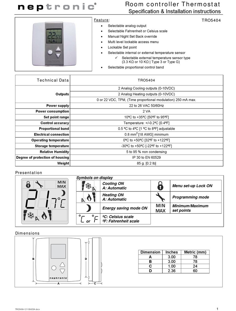
Neptronic
Neptronic TRO5404 installation instructions
Homelux
Homelux HEATWAVE LCD THERMOSTAT instructions
Sygonix
Sygonix tx.1 operating instructions
Computherm
Computherm Q3 operating instructions
Gabarron
Gabarron TA3 Installation instructions and user guide

