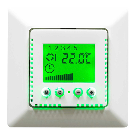
HRT 6018 User manual

Di Mi Do
Fr
Sa SoMo
~
~
~
C
+-
1
2
3456
Electronic Floor Temperature Controller with Timer for Flush Mounting
6018
Setting range approx. 10 - 40 °C (Scale 1 to 4)
Mains voltage: 230 V ~ ± 10% , 50 Hz
Switching current (max.) approx. 12 (4) A
Switch temperature differential: 0.7 K
Temperature sensor: NTC to DIN 44574
length approx. 2 m, Ø approx. 8 mm
Perm. ambient temperature: - 10 to + 40 °C
Connection cables: 2.5 mm2
Energy class: IV = 2.0%
Application area
The electronic controller is used for regulating the floor temperature of individual rooms. Application areas include
electrical heaters (direct heating, area heating, tempering systems, heating mats etc.) and hot water heaters.
Function
The device is equipped with a timer. This enables one or two heating times a day, such as a heating time from 6:00 to 22:00 for a
living room, or from 6:00 to 9:00 and from 17:00 to 22:00 for a bathroom. The reduced heating times with the setback temperature
are in between. The required floor temperature can be set between 10 and 45 °C at any time during operation and the setback
temperature is programmed. The timer can be deactivated (push down right slide switch towards the sun symbol), so that the
device regulates the temperature constantly at the heating temperature set on the setting dial (continuous operation). The heating
can be disconnected from the mains supply on one pole (push left slide switch down towards the blank circle). The clock will
continue to run. The red LED is lit as long as the controller has switched on the heating.
The device is supplied with the following factory settings:
Setback temperature 15 °C
Start 1st heating time 6:00 each day
End 1st heating time 22:00 each day
No second heating time.
Working days are Monday to Friday
Rest days are Saturday and Sunday
If the device is to run with the factory settings, it is only necessary to enter the values for time and weekday (see overleaf).
The controller operates in Block mode. In this mode, the same time program runs on the weekdays and only has to be entered
once. A different time program can be entered for the rest days. Operating in only two blocks considerably reduces the amount of
programming required.
Connecting and commissioning
ATTENTION: Work on the 230 V mains supply must only be carried out by authorised electricians. When connecting the device,
the safety regulations of the VDE (German Association for Electrical, Electronic & Information Technologies) and the local utility
companies must be observed. “Normally closed” valves are required for controlling hot water heating.
Mounting: The temperature controller is mounted in a standard Ǿ 55 mm conduit box (to DIN 49073, part 1). When using
additional intermediate terminals, use of a deep conduit box is recommended. The device is connected according to the circuit
diagram below. The connection cables must be straight and must be stripped by approx. 5 mm. Mounting height approx. 1.5 m
above the floor. Attention! Fit the support ring above the wallpaper and mount the controller on the conduit box using the self-
tapping screws. Then place the caps on the two slide switches, fit the cover on the conduit box and screw the cover tight. Finally fit
the setting dial (align with the groove) to the device.
The floor temperature sensor must be laid in a protective tube at heating
mat level in the centre between the heating mats. The sensor cable must
be laid in a separate protective tube and must not be laid together with the
power supply cables. Attention: Avoid electric shock. Be aware that in the
event of a fault, the power supply may be present on the sensor line. After
the power supply is switched on, it is advisable to press the Reset button
(countersunk on the right of the LED).
L N PE
T
AN
TA (not assigned)
Heating
Floor temperature sensor
L L
N
1

Programming
Switch on the device (push the left slide switch up to the dot symbol).
Switch on the timer (push the right slide switch up to the clock symbol).
Programming is always started by entering the time,weekday, and setback temperature. The switch times are then set. The
programming can be cancelled at any point. If, for example, only the time needs to be adjusted for a DST time change, simply set
the time and then stop any further programming. If no buttons are pressed for 3 minutes, the device accepts the new values
automatically, leaves all other values unchanged and resumes normal operation. The programming is carried out with the buttons
C(= Control), as well as +and -. If you make a mistake or have lost your overview, wait 3 minutes and start from the beginning
again.
Press Cbriefly and set the time using the +and –buttons.
Press Cbriefly and use the +and –buttons to set the weekday (marking at the bottom edge of the display)
Press Cbriefly and set the setback temperature (factory setting 15° C)
Press Cbriefly and set the start of the 1st heating time for weekdays (factory setting 06:00)
Press Cbriefly and set the end of the 1st heating time for weekdays (factory setting 22:00).
Press Cbriefly and set the start of the 2nd heating time for weekdays (0:00, if not required).
Press Cbriefly and set the end of the 2nd heating time for weekdays (0:00, if not required).
Press Cbriefly and set the start of the 1st heating time for rest days (factory setting 6:00).
Press Cbriefly and set the end of the 1st heating time for rest days (factory setting 22:00).
Press Cbriefly and set the start of the 2nd heating time for rest days (0:00, if not required).
Press Cbriefly and set the end of the 2nd heating time for rest days (0:00, if not required).
This completes the programming. Pressing Conce more or simply waiting for 3 minutes will cause the controller to accept the
programmed values for operation and display the current values for time and weekday.
Displays
During operation, the time is shown in the numerical display. During programming, the time and
the setback temperature are displayed alternately. The dots from b to e appear in succession
and indicate
a = A (working days); R (rest days)
b = 1st heating time
c = 1st setback time
d = 2nd heating time
e = 2nd setback time
f = Weekdays
Special functions
Changing the definition of working and rest days
Monday to Friday are factory set as working days, Saturday and Sunday are factory set as rest days. This allocation can be
modified as follows: Press the +and –buttons simultaneously.
Then press the Cbutton several times to select the weekday for which you wish to change the assignment (the relevant allocation
is indicated by Aor R) and change it by pressing the +button and then C. You can change further assignments in the same way.
Pressing +and –simultaneously returns you to Operating mode.
Restricting the temperature range
The temperature setting range of the controller can be mechanically restricted by reducing the rotational angle of the setting dial
(the power supply does not have to be deactivated for this): Carefully prise off the setting dial with a screwdriver.
Then pull out the retaining pin using a pair of long nose pliers. Turn the knurled wheel to restrict the movement of the setting dial.
Refit the retaining pin and replace the setting dial.
Restoring the factory settings
Press the three buttons C, + and –simultaneously. Reprogram the time and weekday.
Mains supply failure is indicated by a flashing display.The time will continue to run for up to 8 hours. The time programs are
retained. If the mains supply failure lasts longer, the time and weekday must then be reset.
Sensor errors (short-circuit or open circuit) is indicated by a flashing LED.
R
A17:00
So
SaFrMiDiMo
a
b
cd
e
Do
f
Table of contents
Other HRT Thermostat manuals
Popular Thermostat manuals by other brands

Water Furnace
Water Furnace IntelliZone2 MasterStat User information

Center
Center 340022 installation guide

Timeguard
Timeguard TRT034 Operating & installation instructions

Pro 1 IAQ
Pro 1 IAQ T605-2 Operation manual

Timeguard
Timeguard TRTWIFI Installation & operating instructions

Pro 1 IAQ
Pro 1 IAQ True Comfort IIII installation guide

Pro 1 IAQ
Pro 1 IAQ RZ251W owner's manual

Uni-Line
Uni-Line Perfect Sense PS4000 Installation and owner's manual

MCOHome
MCOHome MH8S-FC-EU user manual

Pro 1 IAQ
Pro 1 IAQ T601 installation manual

Johnson Controls
Johnson Controls T8680 Owner's manual and installation instructions

INSTEON
INSTEON TempLinc 2441T owner's manual