St George RHSGSPOT User manual

Rangehood
Appliance Operation Manual
INCLUDING INSTALLATION AND CLEANING
RHSGSPOT - 1200mm Wall Mounted Canopy

WELCOME TO ST GEORGE
St George is a proud Australian
company with a heritage of
innovation and quality.
Our success extends to
domestic and overseas markets,
confirming our reputation at the
forefront of appliance excellence.
The elegant simplicity and high
performance features of
St George designs, will
remain contemporary in
many years to come.
6
7
1
4
42
3
5
6
52
3
1
4
7
6
7
2
3
1
4
6
7
2
3
1
3
67
2
1
4
1A 1B
1C 1D
1E
6
7
1
4
5
4
3
2
67
44
2
3
5
67
1
4
432
5
67
1
32
5
8
6
2
1
4
7
53
6
7
4
5
1
2
3
1G
1F
1H
1I
1J 1K
gg
j
h
i
g
g
q
r
s
t
u
f
f
a
2 3
4A 4B 4C
5D
6A - 6B
20b
20b
7-16
7-16
4
5
6
12
13
8
9
14
14
15
18
20a
20a
9
8
19
8
9
B
G
H
11
11
10
17
F

6C
20b
20b
7-16
7-16
4
5
6
12
13
8
9
14
14
15
18
20a
20a
98
19
8
9
3
3
3
2
B
G
H
11
11
10
17
F
1
1
1
1
1

6D - 6I
20b
20b
7-16
7-16
4
5
6
12
13
8
9
14
14
15
18
20a
20a
9
8
19
8
9
1
17
B
G
H
11
11
10
1
1
1
3
3
21
F
1
2
2
3
3

6E
20b
20b
7-16
4
5
6
13
9
8
14
15
18
20a
20a
8
9
19
8
9
B
G
H
11
11
10
17
1
12
1
21
F
2
2
2
3

6F - 6G - 6H
7-16
7-16
5
6
12
13
8
9
18
20a
20a
9
8
19
8
9
1
17
B
H
11
11
10
1
21
2
2
3
14
20b
F
15
G
20b
4
1
1
1
3
22
1H-6H
1H-6H
22
19 17b
7-16
5
6
13
14
15
18
20a
B
G
11
10
17
12
17b
11
H
20a
8
9
4
22a
22b
F
21
6J
20b
20b
7-16
7-16
4
5
6
12
13
8
9
14
14
15
18
20a
20a
9
8
19
B
G
H
11
11
10
17
F
21
8
9
12
13
10
17
17
6K

17
Consult the designs in the front pages referenced in the text by
alphabet letters. Closely follow the instructions set out in this
manual.Allresponsibility, foranyeventualinconveniences,damages
orfires causedby notcomplying withthe instructionsin thismanual,
is declined.
The rangehood must be placed at a minimum distance of 650mm
from the cooking plane for electric, gas and mixed cooktops.
Please confirm measurement with your Local Building Authority.
Therangehoodisequippedwithatopairoutlet
"
B“fordischargeof
fumes to the outside (Ducting version – exhaust pipe and pipe
fixing clamps not provided).
Should it not be possible to discharge cooking fumes and vapour to
the outside, the rangehood can be used in the filter version, by
fitting an activated carbon filter and the deflector
"
F“on the support
(bracket)
"G“. Fumes and vapours are recycled through the top
grille
"H“
bymeansofanexhaustpipeconnectedtothetopairoutlet
"B“
andtheconnectionringmountedonthedeflector
"F“
(exhaust
pipe and pipe fixing clamps not provided).
Expansion wall plugs are provided to secure the rangehood to most
typesofwalls/ceilings.However,aqualifiedtechnicianmustverify
suitability of the materials in accordance with the type of wall/ceiling,
which must be strong enough to take the weight of the rangehood.
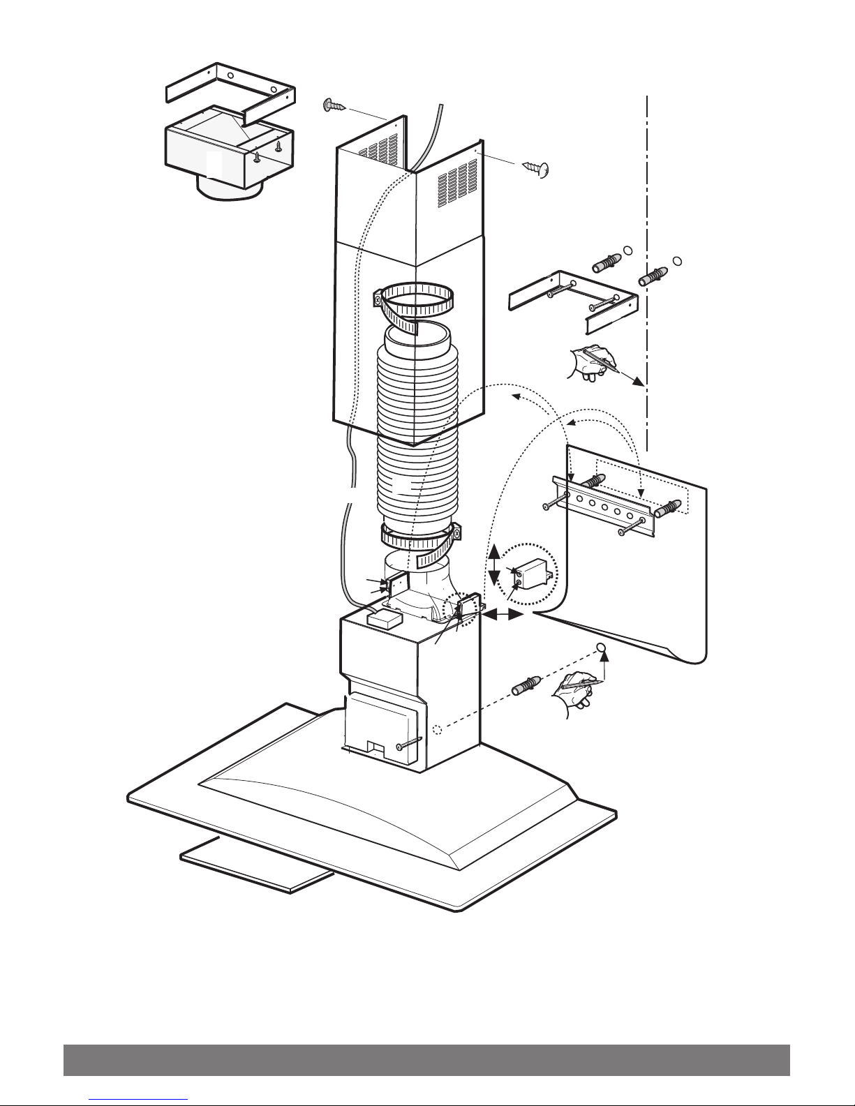
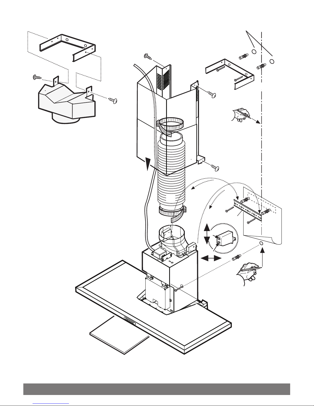
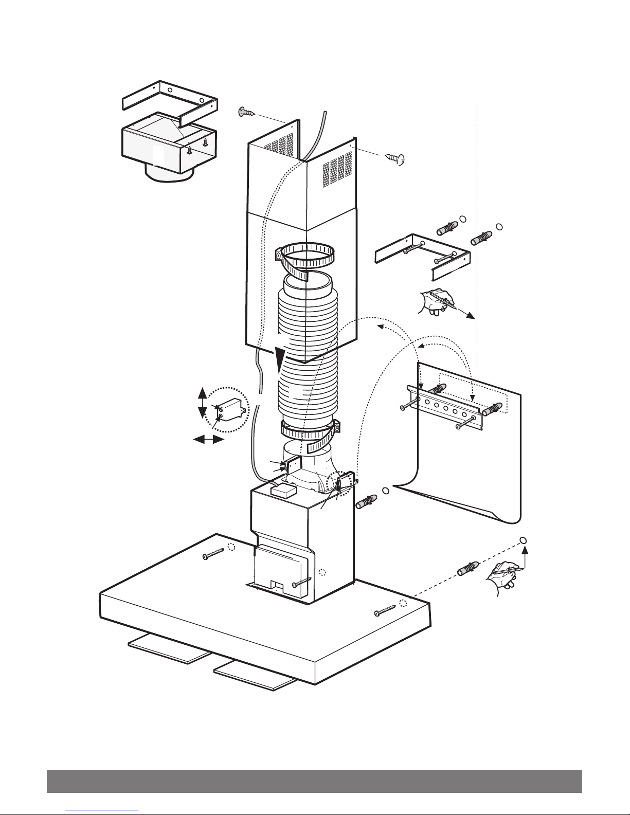
Installation - Fig. 6
Preliminaryinformationforinstallationoftherangehood:
Disconnect the rangehood during electrical connection, by
turning the home mains switch off.
Remove the grease filter/s.
Do not tile, grout or silicone this appliance to the wall. Surface
mounting only.
Do not fix chimney flue to furniture or fly over shelves unless the
chimney flue can be easily removed, in case maintenance is ever
required.
Assemblingthechimneyfluesupport/bracket(3parts):
Thethree partsshould befixedwith 4screws, thesupportextension
is adjustable and should correspond to the internal width of the
telescopic chimney flue.
Assemblingthedeflector (onlywhenadeflectorcomposedof3
parts is supplied – the deflector should be only for the filter
version):
Thethreepartsshouldbefixedwith2screws,thedeflectorextension
is adjustable and should correspond to the width of the chimney flue
support, to which it is then fixed.
==
X
X
H
=
=
X
F
F
G
G
OnlyforthemodelillustratedinFig.1E/6E
Removethe 2screwsmounted onthe insideof thelower partof
the rangehood in the fixing points with the suction group (see
also operation 3).
Attention!
The chimney is predisposed for installation of the filter version.
In certain models where it is required to use the rangehood in the
suctionversionthenitispossibleto overturn theuppersectionof the
chimney and insert it inside the lower section of the chimney so
that the air-exit perforations are not visible. The chimneys in which
this operation is possible are recognisable by their bracket fixing
points "
G" which are repeated also in the lower side of the upper
section of the chimney (see installation sequence 20a-20b).
Attention!
F
or all pre-assembled models:
the mounting operations 1, 2, 3 should not be taken into
consideration, for installation begin at operation 4.
1. Rest the suction unit on a flat surface and thread the lower part
of the rangehood onto it.
2. Make all the electrical connections between the two parts.
3. Permanently fix the rangehood to the suction group with the
screws (consult the figure corresponding to the model in
possession).
4. Using a pencil, draw a line on the wall, extending up to the
ceiling, to mark the centre. This will facilitate installation.
5. Restthedrillingtemplateagainstthewall:theverticalcentreline
printed on the drilling template must correspond to the centre
line drawn on the wall, and the bottom edge of the drilling
template must correspond to the bottom edge of the rangehood
: bear in mind that, when installation is complete, the underside
of the rangehood must be at least 650mm above electric, gas
or mixed cooktops. Please confirm this measurement with
your Local Building Authority.
6. Rest the support bracket on the drilling template so that it
coincides with the dotted rectangle, mark the two outer holes
and drill them, remove the drilling template, insert 2 wall plugs
and fix the rangehood support bracket into place using two
5x45mm screws.
7. Hang the rangehood on the bracket.
8. Adjust the distance of the rangehood from the wall.
9. Adjust the horizontal position of the rangehood.
10. Using a pencil mark the rangehood permanent drill hole inside
the suction group (2 fixing points are necessary for permanent
mounting of the model in fig. 1K/6K).
11. Remove the rangehood from the bracket.
12. Drill at the point marked (Ø8mm - see operation 10).
13. Insert 1 or 2 wall screw anchors according to requirement.
14. Restthechimneysupportbracket"G“againstthewall,touching
the ceiling. Use the support bracket as a drilling template (the
small slot formed on the support must coincide with the line
drawnonthewallasabove–operation4)andmark2holeswith
a pencil, drill the holes (Ø8mm), insert 2 wall plugs.
15. Fix the chimney support bracket to the wall using two 5x45mm
screws.
16. Hook the rangehood onto the bottom bracket.
17. Fix the rangehood into its final position on the wall
(ABSOLUTELY ESSENTIAL).
18. Connect a pipe (pipe and pipe clamps not provided, to be
purchased separately) for discharge of fumes to the connection
ring located over the suction motor unit.

18
If the rangehood is to be used in ducting version, the other end
of the pipe must be connected to a device expelling the fumes
to the outside. If the rangehood is to be used in filter version,
then fix the deflector
"F"
to the chimney support bracket
"G"
and connect the other extremity of the pipe to the connection
ring placed on the deflector
"F"
.
19. Make the electrical connections.
20. Apply the chimney stacks and fasten them at the top to the
chimney support
"G“
(20b) using 2 screws (20a).
Onlyformodelwithopticalfiberspointlighting (Fig.1G-6G):
Check that the chimneys may be removed to permit access to
the optical fibers lamp housing area.
21. Slide the bottom section of the chimney down until it completely
coversthesuctionunitandslotsintothehousingprovidedontop
of the rangehood.
22. Fix the lower section of the chimney with two screws (only for
the model in Fig. 1H/6H-1J/6J).
Replace the grease filter/s and check that the rangehood is
operating correctly.
Electrical connection
The electrical tension must correspond to the tension noted on the
label placed inside the rangehood. Connect the electrical plug,
where provided, to the an easily accessible outlet in conformity with
local standards in force.
Where an electrical plug is not provided (for direct connection to
electrical network) place a standards approved bipolar switch with
an aperture distance of not less than 3mm (accessible) from the
contacts.
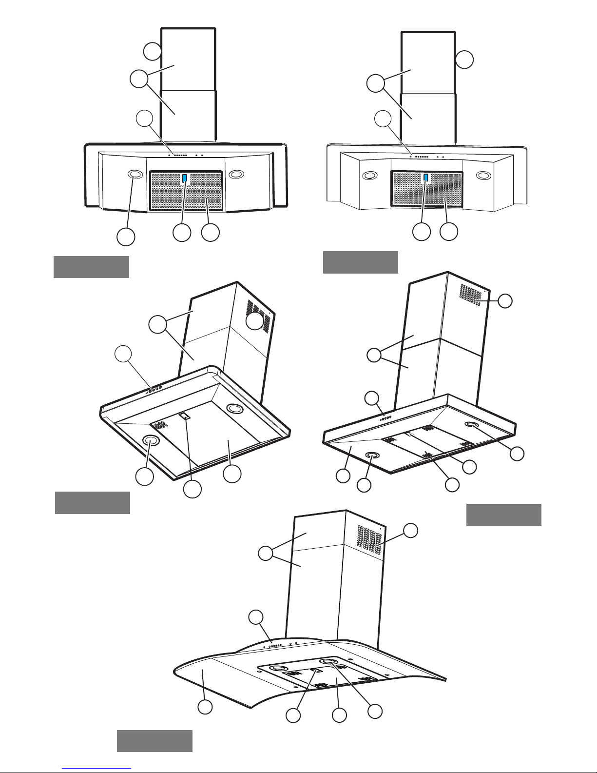
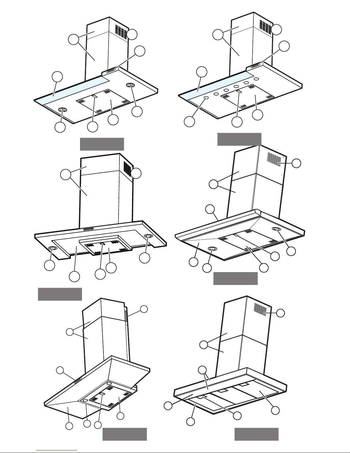
Description of the Rangehood - Fig. 1
1 Control panel
2 Grease filter
3 Grease filter release handle
4 lamp
5 Vapour screen
6 Telescopic chimney
7 Air outlet (used for filter version only)
8
point lighting (only for the model in Fig. 1G)
Operation –
All Rangehood versions
Use the high suction speed in cases of concentrated kitchen
vapours. Itisrecommendedthattherangehoodsuctionisswitched
on for 5 minutes prior to cooking and to leave in operation during
cooking and for another 15 minutes approximately after terminating
cooking.
Operation –
Model with button panel
A. on/off light switch
B. on/off aspiration switch and minimum power selection
B+C. medium power selection aspiration switch
B+D. maximum power selection aspiration switch
a. ON/OFF lighting
b. OFF motors
c. - d. - e.Minimumsuction power(c.), medium (d.),maximum (e.).
f. Operation warning light (where present).
ABCD
a
a b-c d
f
b-c-d-
b-c-d-
a
abcd

19
Operation –
Model with electronic controls
A- Lighting, on/off.
B-Fan off (Stand by)
C-Timer for selected speed (visualises the speed selected
and flashing LED on the lower side of the display).
This knob permits the operation of the rangehood
for an established period:
20 minutes if the speed selected is 1
15 minutes if the speed selected is 2
10 minutes if the speed selected is 3
5 minutes if the intensive speed "P" is selected.
D-Display showing:
•Fanspeed(1-3-P).
•Changegreasefilters (greasefiltersaturationindicator-
F)
Afterwashingtheanti-greasefilter,depressknob"B" for
about 3 seconds. The letter Fwill disappear from the
display.
•Changeactivatedcarbonfilters(carbonfiltersaturation
indicator - "C").
After replacing the charcoal filter, depress knob "B" for
about 3 seconds. The letter "C" will disappear from the
display.
•Whentheled inthelowerright sideis on, itindicatesthat
the rangehoodisreadyforoperation(“standby”position),
theflashingLEDindicatesthatthetimerhasbeenactivated
for selected speed.
Warning!
The active carbon filter saturation function is not activated.
In order to activate the carbon filter saturation indicator,
press buttons
"E
"and
"F"
simultaneously for 3
seconds. Initially, only the letter
"F"
will be displayed,
then after the 3 seconds have passed, letter
"
C" will be
displayed as well, indicating that the carbon filter saturation
control system is active.
To switch off the system, re-press the same two buttons:
the letter
"
C" will appear on display and after 3 seconds
it will disappear and the device will be switched off.
E-Knob to decrease the speed: from intensive speed "P" to
speed level 1.
F-Knob to increase (standby) speed to intensive speed
"
P".
Attention! Intensive speed
"P"
has a duration of 5 minutes
afterwhich therangehood automaticallysetsthe speedto
level 2(suction power).
If the rangehood fails to operate correctly, briefly disconnect it
from the mains power supply for approx. 5 sec. by pulling out the
plug. Then plug it in again and try once more before contacting the
Technical Assistance Service.
Warning!
Alwayspressthefanoffbutton
"
A"beforedisconnectingthe
rangehood from the mains supply.
ABCDEF
Operation –
Model with electronic controls
1-Motor OFF button
2-ON button and motor speed selection button 1 - 2 - 3 - 1 - 2 -
. . . .
3-Speed 1 LED
4-Speed 2 LED and metal grease filter saturation LED (in this
lattercase, theLED willflash -See instructionsongrease filter
cleaning).
Once the grease filters have been cleaned, press button 1for
about 3 seconds until you hear the acoustic signal (beep): the
LED 4 will now stop flashing.
5-Speed 3 LED and active carbon filter saturation LED in the
latter case, the LED will flash - See instructions on active
carbon filter replacement).
Once you have replaced the charcoal filter, press button 1for
about3 secondsuntilyou heartheacoustic signal(beep).LED
5 will now stop flashing.
Warning!
The active carbon filter saturation LED is not activated.
In order to activate the active carbon filter saturation indicator,
press buttons 2and 7simultaneously for 3 seconds. Initially,
only LED 4 will flash, then after the 3 seconds have passed,
LED 5 will also start flashing, indicating that the active carbon
filter saturation control system is active.
To switch off the system, re-press the same two buttons: after
3 seconds LED 5 will stop flashing and the device will be
switched off.
6-Intensive speed LED
7-Intensive speed ON switch
This speed should be used when the concentration of cooking
fumesorodoursisparticularlystrong(forexamplewhenfrying,
cooking fish etc.) The fast speed will run for about 5
minutesandthenreturntothespeedpreviouslysetautomatically
(1, 2 or 3), or switch off if no speed was selected.
Toturnoffthefastspeed,beforetheendofthe5minutes,press
button 1or button 2.
8-OFF lamp button
9-ON lamp button
If the rangehood fails to operate correctly, briefly disconnect it
from the mains power supply for approx. 5 sec. by pulling out the
plug. Then plug it in again and try once more before contacting
the Technical Assistance Service.
1234 56789

20
Maintenance
Prior to any maintenance operation ensure that the rangehood is
disconnected from the power supply.
Cleaning
Therangehoodshould becleanedregularlyinternallyandexternally.
Forcleaninguse acloth moistenedwith denaturedalcohol orneutral
liquid detergents. Avoid abrasive detergents.
Warning:
Failure to carry out the basic standards of the cleaning of the
rangehood and replacement of the filters may cause fire risks.
Therefore we recommend observing these instructions.
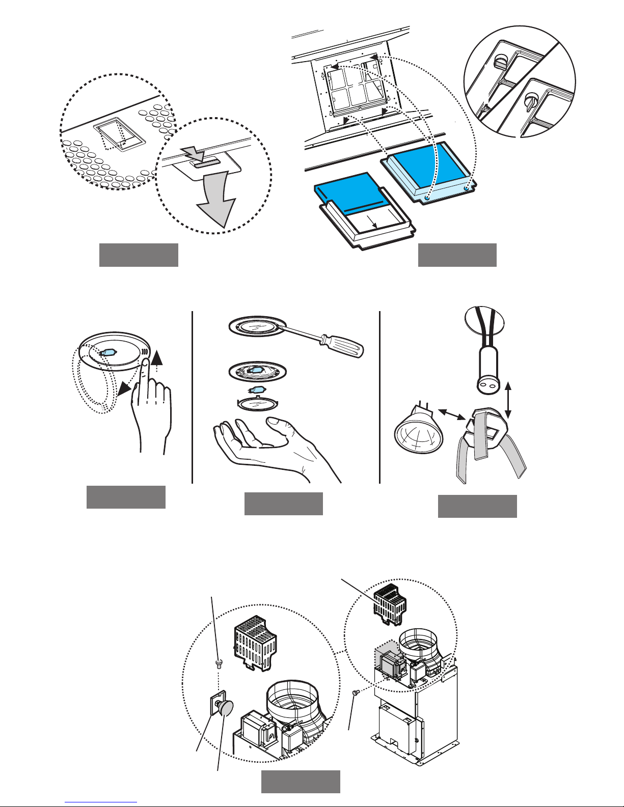
Greasefilter
This must be cleaned once a month (and, for the model with
electronic control panel, every time LED 4 starts to flash – see
preceding page) using non aggressive detergents, either by hand or
in the dishwasher, which must be set to a low temperature and a
short cycle.
When washed in a dishwasher, the grease filter may discolour
slightly, but this does not affect its filtering capacity.
To remove the grease filter, pull the spring release handle "F" - (Fig.
2).
Charcoalfilter(filterversiononly)
It absorbs unpleasant odours caused by cooking.
The charcoal filter can be washed once every two months (when
usingthe rangehood2.5 hoursperday, inaverage and,for the
model with electronic control panel, every time LED 5 starts to
flash – see preceding page) using hot water and a suitable
detergent, or in a dishwasher at 65°C (if the dishwasher is used,
select the full cycle function and leave dishes out).
Eliminate excess water without damaging the filter, then remove the
mattresslocated insidethe plastic frameand putitin theoven for10
minutes at 100° C to dry completely. Replace the mattress every 3
years and when the cloth is damaged.
Removethe filterholderframe byturningthe knobs
"G"
90° thataffix
the chimney to the rangehood (Fig. 3).
Insert the pad "I" of activated carbon into the frame "H" and fit the
whole back into its housing "J".
Replacinglamps-Fig.4
Warning!
Prior to touching the light bulbs ensure they are cooled down.
FormodelsshowninFig.1E:
1. Press on the lamp cover and release to open (fig. 4A).
2. Replace the damaged light bulb.
Only use halogen bulbs of 20W max (G4), making sure you do
not touch them with your hands.
3. Close the lamp cover (it will snap shut).
FormodelsshowninFig. 1A-1B-1C-1D-1F-1H-1I-1K:
1. Extract the guard by levering it off with a small screwdriver or
similar tool.(fig. 4B).
2. Replace the damaged light bulb.
Only use halogen bulbs of 20W max (G4), making sure you do
not touch them with your hands.
3. Close the lamp cover (it will snap shut).
FormodelsshowninFig.1J:
1. Usea smallscrewdriver asa leveron theborders ofthe lampin
order to remove the lightbulb.
2. Unthread the connector
"A“
.
3. Slideoutthelightbulbtobereplacedandreplacewithanew12V
20W 30° Ø35 12V GU4 PHILIPS STANDARD LINE code
425409.
4. Carry out the replacement and mount the new lightbulb by
following instructions in the reverse.
FormodelsshowninFig.1G:
Dismount the chimneys: remove the two screws (20 a) that
attaches the upper chimney to the support "G“ (Fig. 6).
Remove the box
"
Q“: remove the screw
"R
“that secures the
rangehood.
Remove the lamp housing "S": remove the screws
"T“
that
position the housing in the lamp housing area.
Extract the damaged lamp.
Use only PHILIPS type 14515 (GX 5.3) 12V - 75W halogen
bulbs..
Reposition and secure the lamp housing
"S“
and the box
"Q"
and remount the chimneys.
Formodels showninFig. 1K:
Certain versions of this rangehood provide for an incandescent
lampat 40Wmaximum (E14),removethe greasefilter toaccessthe
lamp housing and carry out any replacements.
If the lights do not work, make sure that the lamps are fitted
properly into their housings before you call for technical
assistance.
Caution
Thisapplianceis designedto beoperated byadults. Childrenshould
notbe allowed totamperwith thecontrols orplaywith theappliance.
Donotusetherangehood where thegrillis notcorrectlyfixed! The
suctioned air must not be conveyed in the same channel used for
fumes discharged by appliances powered by anything other than
electricity. The environment must always be adequately aerated
when the rangehood and other appliances powered by anything
other than electricity are used at the same time. Flambé cooking
witharangehoodisprohibited.Theuseofa free flameisdamaging
to the filters and may cause fire accidents, therefore free flame
cooking must be avoided. Frying of foods must be kept under close
control in order to avoid overheated oil catching fire. Carry
out fumes discharging in accordance with the regulations in force
by local laws for safety and technical restrictions.
WARNING!
The appliance is not intended for use by young children or infirm
personswithoutsupervision.

DOMESTIC WARRANTY - FULL FIVE YEAR WARRANTY
In addition to all statutory rights which you, the Consumer, have under the relevant laws in respect of this
appliance, during the first five years of ownership as the original purchaser of this St George appliance, we
guarantee that any fault caused by faulty material or workmanship becoming apparent will be rectified free of
charge for parts and labour,provided that all service is performed during normal working hours by St George
or their designated Agents. Where the appliance is installed outside the normal servicing area of the above,
the Purchaser must pay for the cost of transporting the appliance to and from the Agent or the Agent’s
travelling cost to and from the Purchaser’s home.
COMMERCIAL WARRANTY - ONE YEAR WARRANTY
When this appliance is installed in a commercial application, you, the Consumer, have under the relevant
laws in respect of this appliance, during your first one year of ownership as the original purchaser of this
St George appliance, we guarantee that any fault caused by faulty material or workmanship becoming
apparent, will be rectified free of charge for parts and labour, provided that all service is performed during
normal working hours by St George or their designated Agents. Where the appliance is installed outside the
normal servicing area of the above, the Purchaser must pay for the cost of transporting the appliance to and
from the Agent or the Agent’s travelling cost to and from the Purchaser’s home.
WHAT THESE WARRANTIES DO NOT COVER
We are not responsiblefor any damage or malfunctionunless caused by a defect in material or workmanship.
This includes but is not limited to abuse, misuse, improper installation and transportation damage. We are
not responsible for any consequential damages from any malfunction.
WARRANTY DOES NOT COVER REPLACEMENT OF LIGHT
GLOBES OR GLASS BREAKAGE DUE TO IMPACT
In case of fractured glass do not use your appliance.
WARRANTY REGISTRATION
Please complete warranty details below. Please retain together with your proof of purchase document.
SERVICE ASSISTANCE
WARRANTY AND SERVICE
service.
These documents will need to be viewed by our Service Representative should you request in warranty
To assist you when phoning our After Sales Service number to arrange a service call please
complete the following details and have them ready when you call.
Model Number ________________________________________Date of purchase_____________________________
St George Store purchasedfrom__________________________Date of installation____________________________
ST GEORGE AFTER SALESSERVICE
1300 305 366
The Consumer, must make the appliance available for servicing and shall bear any costs incurred for
any de-installation and/or re-installation required to make the appliance available for servicing.
St George are not liable for any consequential damage incurred during de-installation or re-installation.

A Tradition of Excellence
1300 305 366
Table of contents
Other St George Ventilation Hood manuals


Popular Ventilation Hood manuals by other brands

Gorenje
Gorenje S3 IHGC963S4X manual

KOBE
KOBE ISX2136SQB-1 Installation instructions and operation manual

U.S. Products
U.S. Products ADVANTAGE-100H Information & operating instructions

Kuppersberg
Kuppersberg DUDL 4 LX Technical Passport

Framtid
Framtid HW280 manual

Thermador
Thermador HGEW 36 FS installation manual


