St George RHSGALA User manual

Rangehood
Appliance Operation Manual
INCLUDING INSTALLATION AND CLEANING
RHSGALA - 900mm Wall Mounted Canopy

WELCOME TO ST GEORGE
St George is a proud Australian
company with a heritage of
innovation and quality.
Our success extends to
domestic and overseas markets,
confirming our reputation at the
forefront of appliance excellence.
The elegant simplicity and high
performance features of
St George designs, will
remain contemporary in
many years to come.

4
1
3
3
3
2
Fig. 1
Fig. 2 Fig. 3
Fig. 4
5
a
Instructionson Mounting and Use
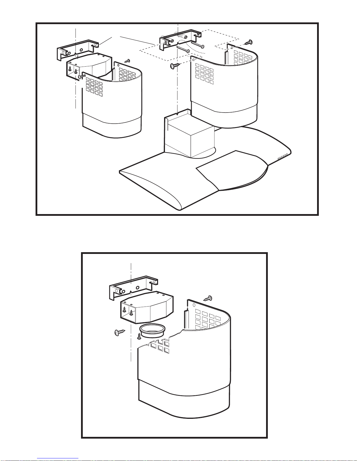
Fig. 5
Fig. 6
RR
R
M
R
R
Q
P
L
L
R
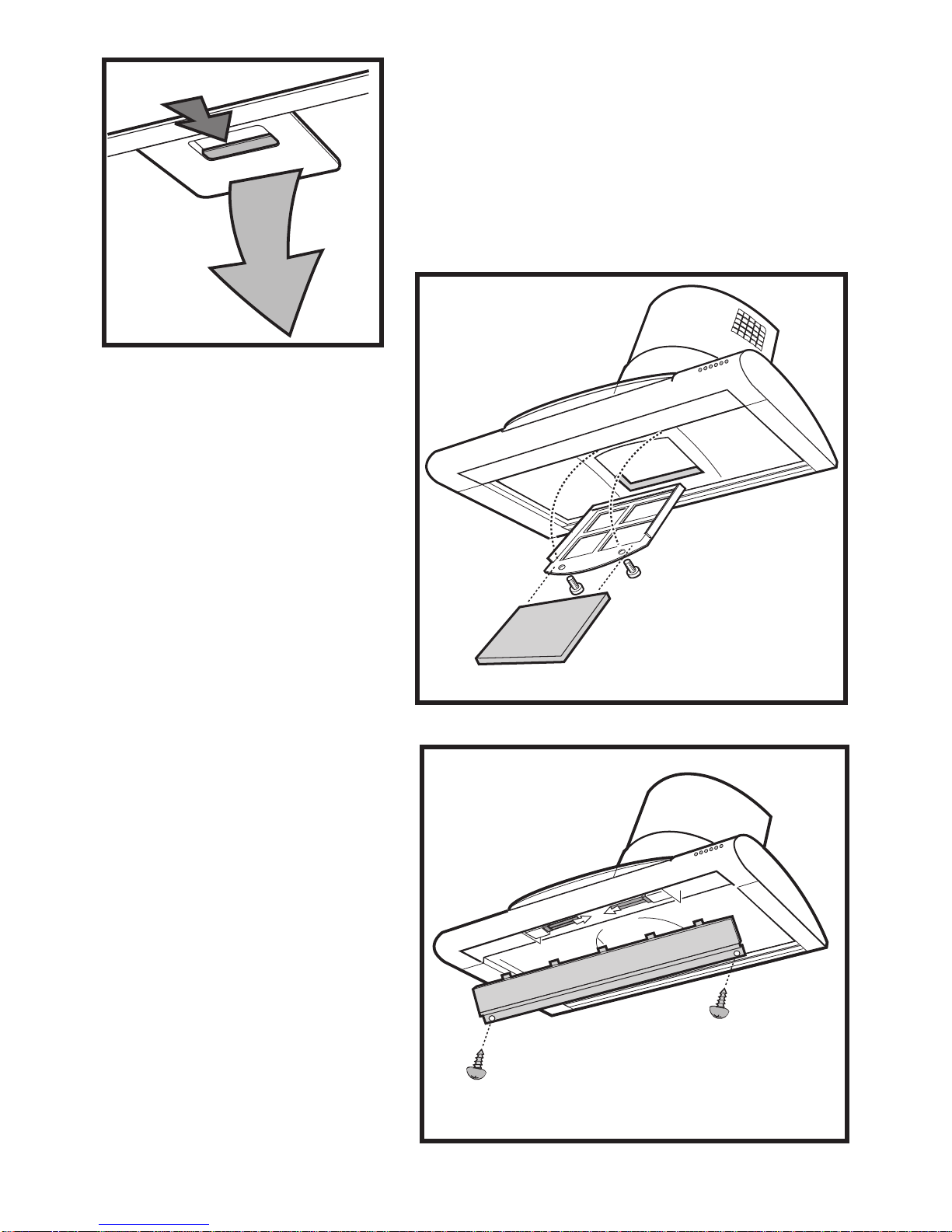
Fig. 7
Fig. 8
Fig. 9
a
b

4
View of the Rangehood - Fig. 1
1.Controlpanel
2.Work-light
3.Greasefilters
4.Telescopicchimney
5.Outlet(OnlyforFilterversion)
Use:Two systems are available
Exhaustmode
Vapours are extracted outside through an
exhaustingpipethatisaffixedtotheconnection
ringabovetherangehood.
Diameteroftheexhaustingpipemustbeequalto
thatoftheconnectionring.
In the horizontal runs,the duct must be slightly
slanted(about10°)anddirectedupwardstovent
theaireasilyfromtheroomtotheoutside.
Attention!
If the rangehood is supplied with a carbon
filter, then it must be removed.
Filter version
The air is filtered through a carbon filter (for its
installation see paragraph "Carbon Filter")and
recirculatedintotheroomthroughthegratingon
thechimney.
Attention!
Iftherangehoodisnotsuppliedwithacarbon
filter, it must be ordered and mounted.
This version is used when there is no exhaust
ductforventingoutdoorsorwhenitisimpossible
toinstallone.
Installation
Therangehoodmustbeplacedataminimum
distance of 650mm above an electric, gas or
mixedcooktop.Please confirmthis
measurementwithyourLocalBuilding
Electricconnection
Beforecompletinganyconnection,makesurethe
house voltage corresponds with the voltage
indicatedonthelabelaffixedinsidetherangehood.
Itisadvisabletocallaqualifiedtechniciantomake
theelectricalconnection.
Appliance fitted with a plug.
Connect it to a socket which conforms with
currentregulations.
Ifyouintendtoconnectitdirectlytotheelectric
mains, remove the plug and fit an approved
bipolarswitchwithaminimumcontactopeningof
nolessthan3mm.
If the plug is not accessible once it has been
inserted in the socket, it will be necessary
tofitanapprovedbipolarswitchwithaminimum
contactopeningofnolessthan3mm.
Themanufacturersarenotliableforanyproblems
caused by the user’s failure to observe the
aboveinstructions.
Mounting on the wall
1. Restthetemplatecorrectlyagainstthewall. The
lower cornerofthetemplatecorrespondstothe
lowercorner ofthe rangehood. Fig. 2.
2.Acrossismarkedonthetemplatetoindicate
thecentre. Markthispointonthewall. Fig.2.
3.Drilltwoholes(Ø8mm)inthewallatthepoints
indicated,insertthestops(Ø8mm)andscrew
inthehooksprovided. Fig.2.
4.Hangthe rangehoodandadjustitsposition
using the screws on the hooks. Fig. 3.
5.Thereferencepoint“a”markedonthebodyof
therangehoodmustcoincidewiththeline
you have drawn on the wall. Fig. 3.
6.Oncetherangehoodhasbeencorrectly
aligned,removethegreasefilter.
7.Frominsidetherangehood,markthefinal
pointsatwhichthehoodhastobefixedtothe
wall. Fig.4. Toreachthesepointsitwillbe
necessarytoremoveactivatedcarbonfilter
frame until the filter itself is replaced -
8.Removetherangehood.
9.Drill2holes(Ø8mm)andinserttheplugs(Ø
8mm).Fig.4.
10.Hangtherangehoodupagain.
11.Fix the rangehood into its final position
using 2 screws (Ø 5x45 mm). Fig. 4.
12.RemovethetelescopicchimneysupportMby
unscrewingthesidescrewsR(oneoneach
side - these screws must be kept). Fig. 5.
13.Remove the air pipe Lfrom the telescopic
chimney support M; to do this, unscrew the
Authority.
see Fig. 9.

5
fourscrews(Ø2,9x9,5mm)fixingtheairpipe
tothe support (thesescrews must bekept).
Fig.5.
14.Fitthetelescopicchimneysupporttothewall,
atapointclosetotheceiling. Thetelescopic
chimney support has a reference mark P,
which must coincide with the line that you
have already drawn on the wall. Fig. 5.
15.Usingapencil,markthetwoholesrequiredto
fixthesupportanddrilltheholes(Ø8mm).
Fig.5.
16.Inserttwoplugsandfixthetelescopicchimney
support Musing 2 screws size (5x45 mm).
Fig.5.
17.During installation the plug must not be
connectedtothe power supply.
18.Selecttherangehoodoperatingmode.
19.Exhaust mode:
Iftheconnectorringhasnotyetbeeninstalled,
itmustbefittedatthispoint(QinFig.6,bayonet
connector). Turn it in a clockwise direction
andfixittotheairpipeLusingascrew. Insert
theairpipeintothetelescopicchimneysupport
and fix it with four screws (Ø 2.9 x 9.5 mm).
Fig.6.
Fixthe150mmdiameterABSpipetothe
rangehoodoutlet,andconnectittotheairpipe
connectorring.Ensurethattheotherend
Filter version:
20.Therangehoodcannowbeconnectedtothe
powersupply.
21.Ifanon-returnflaphasbeeninstalledor
is required, ensure that it opens and closes
properly.
22.Fixthetoppartthetelescopicoutletpipetothe
relativesupport,usingthetwo3mmdiax9mm
screws R.Fig. 5/6.
23.Slidethebottompartofthetelescopicoutlet
pipedownwarduntilitrestsinitshousingon
thetopoftherangehood.
24.Replacethegreasefilters.
Functions
—Therangehoodisprovidedwithamotorwith
several speeds. For the best performance
werecommendusingthelowspeedsinnormal
conditionsandthehighspeedsinparticular
cases of strong odour and vapour
concentration.
—We recommend starting up the rangehood a few
minutes before cooking and keeping it running
until all the odours have been eliminated.
Descriptions and functions of the
control panel
-Thecontrolpanelislocatedonthefrontofthe
rangehood.
=Lighting,on/off.
=Fan off
=Fast speed switch (P+ the led on the
bottomrightsideofthedisplayflashes).
Thisspeedshouldbeusedwhenthe
concentration of cooking fumes or
odours is particularly strong (for
examplewhenfrying,cookingfishetc.).
The fast speed will run for about 5
minutesandthenreturntothespeed
previouslysetautomatically(1,2or3),
orswitchoffifnospeedwasselected.
To turn off the fast speed, before the
endofthe5minutes,press button
and .
=Display showing fan speed (1-3-P),
change grease filters (grease filter
saturation indicator - F) and change
activated carbon filters (carbon filter
saturationindicator-C).
AlightedLedontherightbottomside
indicatestherangehoodisinstand-bymode.
discharges into the open air.

6
Warning!
The active carbon filter saturation
functionisnotactivated.
In order to activate the carbon filter
saturationindicator,pressbuttons
and simultaneouslyfor3seconds.
Initially,theletterFwill bedisplayed,
thenafterthe3secondshavepassed,
letter Cwill be displayed as well,
indicating that the carbon filter
saturationcontrolsystemisactive.
Toswitchoffthesystem,re-pressthe
sametwobuttons.TheletterCwill
appear on the display.After approx
3 seconds it will disappear and
the device will be switched off.
=Decrease fan speed button for
reducingspeedofmotorfrom3down
tospeed1.
=Increase fan speed button for
increasingspeedofmotorfrom1to3.
If the rangehood fails to operate correctly,
briefly disconnect it from the mains power supply
forapprox.5sec.bypullingouttheplug.Thenplug
itinagainandtryoncemorebeforecontactingthe
TechnicalAssistanceService.
Always press the fan off button before
disconnecting the rangehood from the
mains supply.
Warning!
—This appliance isdesignedtobeoperatedby
adults. Children should not be allowed to
tamper with the controls or play with the
—The rangehood cannot be connected to
fluesofotherappliancesthatrunonenergy
sourcesotherthanelectricity.
—When the rangehood is used at the same
timeasotherappliancesthatrunonenergy
sourcesotherthanelectricity,provisionmust
bemade for an adequate supply ofair.
—Nofoodmustbecookedflambéunderneath
therangehood.Theuseofanunprotected
flameisdangerousforthefiltersandcouldcause
a fire.Therefore, never use an open flame
never leavethepanunattendedbecausethe
cookingoilcouldflareup.
—Please, keep to the provisions of official
directives regarding the question of fume
discharge.
—The manufacturers refuse to accept any
responsibility for damage to the rangehood
oritscatchingonfirebecauseoffailureto
observetheaboveinstructions.
Maintenance
Beforeperforminganymaintenanceoperation,
isolate the rangehood from the electrical
supplybyswitchingoffattheconnectorand
removing the connector fuse.
Oriftheappliancehasbeenconnectedthrough
aplugandsocket,thentheplugmustberemoved
fromthesocket.
Grease Filter (1 of 2 pieces)
It’sfunctionistoretainthegreaseparticles
Thegreasefilterhasanunlimitedlifespanand
can be washed by hand or in the dishwasher
(65°)withsuitabledetergents.
Whenwashedinthedishwasherthegreasefilter
maydiscolourbutthefiltrationcharacteristicswill
not be effected.
Thegreasefiltermustbewashedatleastonce
amonthoreachtimetheletterForalternatively
theselectedvelocityappearsTodisassemble
thegreasefilterusetheappropriatehandles.First
pullthehandleback(a)andthendown(b) Fig.
7.
Leavetodrywithoutdamagingthegreasefilter
beforere-assembling.
After washing the grease filter reverse
thestepsusedtodisassemblethegreasefilterin
ordertoreassemble.
Once the grease filters have been set in place
pressbutton and simultaneouslyforabout
threesecondsuntiltheletterFshownondisplay
disappears.
Carbon Filter
The carbon filter extracts odours emitted when
cookingintotheflue.
It must be mounted on the inside of the
rangehood.
Undernormalusethecarbonfiltermustbewashed
every two months, or each time the display
flashestheletterCandcanbewashedbyhand
orinthedishwasherat65°c.
When washing it in the dishwasher it must be
washed without any dishes using a suitable
under the rangehood. When frying foods,
appliance.

7
detergent.
Before remountingfirst gentlywipewitha
sponge to remove excess water and dry
intheovenataconstanttemperatureofa
maximumof100°Cfor10minutes.
The carbon filter must be changed every 2
years
1.Disconnect the rangehood from the
electrical point.
2.Removethegreasefilter(Fig.7)
3.Unscrew the screws that hold the frame
(Fig8.)andremovethecarbonfilter(inthe
case of cleaning or substituting) insert the
carbon filter (in the case of first use).
4. Replacefilter.
5.Replacethesupportsofthecarbonfilterwith
the two screws of the frame (Fig 8).
6.Remountthegreasefilter
Onceyou have performedthemaintenance
operation, press the buttons and
similtaneouslyfor 3 seconds until the letter
Cflasheson the display.
Ifthisisthefirsttimeanewcarbonfilterisbeing
inserted, once the grease filters have been
insertedcheckthatthesaturationindicatorforthe
carbonfilterisactive.(Seeparagraph“Functions
-Descriptionsandfunctionsofthecontrolpanel.”)
Cleaning
To clean the outside of the rangehood use
aclothmoistenedwithdenaturedalcoholorneutral
liquid detergents. Never use products
containing abrasive detergents.
Wipebrushedstainlesssteelinthesamedirection
asthebrushingtoavoidscratching.
Clean the external surface of the rangehood
approximatelyonceevery10days.
Attention
Failure to observe the rules for cleaning the
applianceandchangingandcleaningthefilters
maycausefires.
Therefore, we recommend observing these
instructions.
Replacing the light bulbs - Fig 9
1. Unplugfromthepowersupply.
2.Removethegreasefilter.
3.Remove the screws that protect the light
bulbs.
4.Removethedamagedlightbulbandreplace
withthesametypemax.11watts(Lightbulb
PL)
5.Replaceandaffixthelightbulbcover.
6.Replacethegreasefilter
7.If the light does not function, before calling
technicalassistance,checkthatthelightbulb
hasbeen fittedcorrectly.
WARNING!Theapplianceisnotintendedforuseby
youngchildrenorinfirmpersonswithoutsupervision.

DOMESTIC WARRANTY - FULL FIVE YEAR WARRANTY
In addition to all statutory rights which you, the Consumer, have under the relevant laws in respect of this
appliance, during the first five years of ownership as the original purchaser of this St George appliance, we
guarantee that any fault caused by faulty material or workmanship becoming apparent will be rectified free of
charge for parts and labour,provided that all service is performed during normal working hours by St George
or their designated Agents. Where the appliance is installed outside the normal servicing area of the above,
the Purchaser must pay for the cost of transporting the appliance to and from the Agent or the Agent’s
travelling cost to and from the Purchaser’s home.
COMMERCIAL WARRANTY - ONE YEAR WARRANTY
When this appliance is installed in a commercial application, you, the Consumer, have under the relevant
laws in respect of this appliance, during your first one year of ownership as the original purchaser of this
St George appliance, we guarantee that any fault caused by faulty material or workmanship becoming
apparent, will be rectified free of charge for parts and labour, provided that all service is performed during
normal working hours by St George or their designated Agents. Where the appliance is installed outside the
normal servicing area of the above, the Purchaser must pay for the cost of transporting the appliance to and
from the Agent or the Agent’s travelling cost to and from the Purchaser’s home.
WHAT THESE WARRANTIES DO NOT COVER
We are not responsiblefor any damage or malfunction unless caused by a defect in materialor workmanship.
This includes but is not limited to abuse, misuse, improper installation and transportation damage. We are
not responsible for any consequential damages from any malfunction.
WARRANTY DOES NOT COVER REPLACEMENT OF LIGHT
GLOBES OR GLASS BREAKAGE DUE TO IMPACT
In case of fractured glass do not use your appliance.
WARRANTY REGISTRATION
Please complete warranty details below. Please retain together with your proof of purchase document.
SERVICE ASSISTANCE
WARRANTY AND SERVICE
service.
These documents will need to be viewed by our Service Representative should you request in warranty
To assist you when phoning our After Sales Service number to arrange a service call please
complete the following details and have them ready when you call.
Model Number ________________________________________Date of purchase_____________________________
St George Store purchasedfrom__________________________Date of installation____________________________
ST GEORGE AFTER SALESSERVICE
1300 305 366
The Consumer, must make the appliance available for servicing and shall bear any costs incurred for
any de-installation and/or re-installation required to make the appliance available for servicing.
St George are not liable for any consequential damage incurred during de-installation or re-installation.

A Tradition of Excellence
1300 305 366
Table of contents
Other St George Ventilation Hood manuals


Popular Ventilation Hood manuals by other brands

LG
LG HCEZ2426S owner's manual

Aroua
Aroua Vortix installation instructions

Sirius Satellite Radio
Sirius Satellite Radio ALFRESCO SLEM80 installation instructions

KOBE
KOBE RA3830SQB-1 Installation instructions and operation manual

FALMEC
FALMEC Mira island Instruction booklet

ROBLIN
ROBLIN ATRIUM 600 Dimensions

Parmco
Parmco R6W-501-1 Installation and operating instructions

Bosch
Bosch DKE 945 E GB Operating and installation instructions

Beko
Beko BHCB66741BZGSH user manual

VentAHood
VentAHood JDIH ISLAND installation instructions

Zanussi
Zanussi Block 642221 Specifications

LUX
LUX KI30LCD Installation and user guide


