ST Group PIRANHA ST 500 User manual
ST 500 "PIRANHA"
MULTIFUNCTIONAL DETECTION DEVICE
USER MANUAL
ST Group, Ltd.
St. Petersburg, Russia
+7 (812) 412-33-21
info@smersh.pro
www. spymarket.com

ST 500 "Piranha" Operation Manual: General Information
1
CONTENTS
1
GENERAL INFORMATION………………………………………………………………………………………..…
3
1.1
Purpose and Capabilities………………………………………………………………….……………………………………
3
1.2
Specification………….………………………………………………………………………………………………………….……
4
1.3
Description of Specification Items.……………………………………………………………………………………….
5
1.4
Power Supply…………………………………………………………………………………………………………………………
8
1.5
Technical Specifications…………………………………………………………………………………………………………
9
2
INTERFACE OPTIONS………………………………………………………………………………………………….
10
2.1
Turning the Device On/Off…………………………………………………………………………………………………….
10
2.2
Main Menu…………………………………………………………………………………………………….….……………………
10
2.3
Status Bar……………………………………………………………………………………………………..………………………
11
2.4
SETTINGS Service Mode……………………………………………………………………………………..……………….
11
2.4.1
Setting the Date…………………………………………………………………………………………………………………….
12
2.4.2
Setting the Time……………………………………………………………………………………………………………….……
12
2.4.3
Setting the Language……………………………………………………………………………………………..……….……
12
TECHNICAL DESCRIPTION
3
SELECTIVE HF DETECTOR Channel………….…..…..……………………………………….……………
13
3.1
PANORAMA Mode……………………………………………………………………………………………………….……….…
13
3.2
DIFFERENTIAL Mode…………………………………………………………………………………………….……………….
15
3.2.1
FIXED FREQUENCY ANALYSIS Function….…………………………………………………………………….…….
16
3.2.2
SET "0" Function…………………………………………………………………………………………………………….….…
17
3.2.3
OSCILLOSCOPE Function…………………………………………………………………………………………………..…
18
3.3
AUTOMATED Mode…………………………………………………………………………………………………………………
19
3.3.1
FREQUENCY TUNING Function……..…………………………………………………..…………………………………
20
3.3.2
OSCILLOSCOPE Function….…………………………………………….…………………………………………………….
21
3.4
WIRELESS COMMUNICATION Mode ………………………………………………………………………………….…
21
3.4.1
MOBILE DEVICES MONITORING Function.…..………………………………………………………………….….
21
3.4.2
BASE STATIONS MONITORING Function …….…….……………………………………………………………….
22
3.4.3
USER LIST Function…………..……………..………………………….…..…………………………………………….….
23
3.4.4
ANALYZING DETECTED SIGNALS Function.……………..………………………………………………………….
23
4
INFRARED DETECTOR Channel…………………………………………………………………..………….….…
26
4.1
DIFFERENTIAL Mode…………………………………………………………………………………………….……………….
27
5
CONNECTING ST 500 TO WIRE LINES………………………………………………………………………
28
5.1
Connecting to Electric Mains…………………………………………………………………………………….…………..
28
5.2
Connecting to LAN…………………………………………………………………………………………………………………
28
5.3
Connecting to Telephone Lines…………………………………………………………………………………………….
29
5.4
Connecting to Low Current Multi-Core Cables without Connectors…………………………………….
30
6
WIRED RECEIVER Channel (WR)…………….…………………………………………………….…………
31
6.1
Circuit Type Selection……………………………………………………………………………………………………………
31
6.2
Frequency Range Selection……….…………………………………………………………………………….……………
31
ELECTRIC MAINS TESTING
6.3
PANORAMA Mode (Electric Mains Testing) …………………………………………………………….……………
32
6.4
DIFFERENTIAL Mode………………………………………………………………………………………………………………
34
6.4.1
FIXED-FREQUENCY ANALYSIS Function….………………….……………………………………………………….
35
6.4.2
OSCILLOSCOPE Function….…………………………………………………………………………………………………..
36
6.5
AUTOMATED Mode…………………………………………………………………………………………………………………
37
6.5.1
FREQUENCY TUNING Function…………………………………………………………………………………………..…
38
6.5.2
OSCILLOSCOPE Function………………………………………………………..…………………………………………….
38
LOW CURRENT CIRCUIT TESTING
6.6
ELECTRONIC SWITCH CONTROL Mode…………………………………………………………………………………
39
6.7
ELECTRONIC SWITCH SETTINGS Mode……………………………………………………………………………….
41
6.8
PANORAMA Mode (Low Current Circuit Testing)……………………………………………………….…………
42

ST 500 "Piranha" Operation Manual: General Information
2
7
LOW FREQUENCY AMPLIFIER Channel (LFA)…………………………………………………….……
44
7.1
ELECTRONIC SWITCH CONTROL Mode …………………………………………………………………………….…
44
7.2
ELECTRONIC SWITCH SETTINGS Mode……………………………………………………………………………….
46
7.3
Setting the Gain…………………………………………………………………………………………….………………………
46
7.4
Setting the Bias Voltage……………………………………………………………………………………………………….
47
7.5
AUTOMATED Mode…………………………………………………………………………………………………………………
48
7.6
OSCILLOSCOPE……………………………………………………………………………………………….…………………….
48
7.7
SPECTRUM ANALYZER…………………………………………………………………………………….…………………….
49
8
ST 500 SOFTWARE…………………………………………………………………………………………………………..
51
8.1
Purpose………………………………………………………………………………………………………………………………….
51
8.2
Functionality………………………………………………………………………………………………………………………….
51
8.3
PC Requirements………………………………………………………………….……………………………………………….
51
8.4
Installation…………………………………………………………………………………………………………………………….
51
8.5
Graphical Interface………………………………………………………………………………………………………………..
52
8.6
Operation Modes……………………………………………………………………………………………………………….….
52
8.6.1
RANGES HIGHLIGHTING Mode………………………………………………………………………..…………………..
53
8.6.2
MOBILE BANDS Mode…….……………….…………………………………………………………….….………………….
55
8.6.3
BASE BANDS Mode……….………………………………………………………………………………………….…………..
58
8.6.4
USER BANDS Mode ………………………………………………………………………….……………………………….…
58
8.6.5
FIRMWARE UPDATE Mode ………………………………………………………………………………….………………..
58
USE GUIDELINES
9
USE GUIDELINES…………………………………………………………….….……………………………………………
60
9.1
Guidelines for Use of SELECTIVE HF DETECTOR Channel………………...…………………………….…
60
9.1.1
Search in the AUTOMATED Mode ……………………………………………………………………….……………….
60
9.1.2
Search in the PANORAMA Mode and DIFFERENTIAL Mode………………………….…….……………….
61
9.1.3
Search in the WIRELESS COMMUNICATION Mode ………………………………………………………….
62
9.1.4
Localization of the Source of Detected Signal…………………………………………………….…………......
63
9.2
Guidelines for Use of INFRARED DETECTOR Channel……………………………………….…………….….
64
9.2.1
Selection of "False" Signals…………………………………………………………………………………………….…….
64
9.3
Guidelines for Use of the WIRED RECEIVER Channel………………………….……………….…………….
65
9.3.1
Electric Mains Testing…………………………………………………………………………………………………….……..
65
9.3.2
Low Current Circuit Testing…………………………………………………………………………………………….…….
67
9.4
Guidelines for Use of LOW FREQUENCY AMPLIFIER Channel………………….……………………..…..
68
9.4.1
Search for Active Microphones in an Analog Telephone Line…………….……………………………….
69
9.4.2
Activation of Electret Microphones in an Analog Telephone Line………….…….………………………
70
9.5
Localization of the Signal Source Detected by the "WR" or "LFA" Channels………………………
70
9.5.1
Acoustic Method…………………………………………………………………………………………………….………………
70
9.5.2
Localization with ST 500 and Non-Linear Junction Detector………………………………………….……
71
SUPPLEMENTS
10
Supplement #1. Functions of the Controls…………………………………………………….…………
72
10.1
Basic Settings…………………………………………………………………………………………………………………………
72
10.2
SELECTIVE HF DETECTOR…………………………………………………………………………………………….………
73
10.3
IR DETECTOR…………………………………………………………………………………………………………………………
76
10.4
WIRED RECEIVER………………………………………………………………………………………………………….………
76
10.5
LOW FREQUENCY AMPLIFIER………………………………………………………………………………………….……
80
11
Supplement #2. Typical Settings of the Electronic Switch………………………………….
82
12
Supplement #3. Reference Information……………………………………………………..…………
84
12.1
"Twisted Pair" Cable……………………………………………………………………………………………………….….…
84
12.2
RJ Connectors………………………………………………………………………………………………………….…………….
84
12.3
Wiring Scheme of a Four Twisted Pair Cable ………………………………………………………………………
84
12.3.1
Wiring Scheme EIA/TIA-568A……………………………………………………………………………………………….
86
12.3.2
Wiring Scheme EIA/TIA-568B……………………………………………………………………………………………….
85
12.4
Crossover Wiring Scheme……………………………………………………………………………………………………..
85
12.5
Wiring Scheme of a Three, Two, and One Pair Twisted Cable…………………………………………….
86
12.6
Reference Information on Telephone Lines………………………………………………………………………….
86

ST 500 "Piranha" Operation Manual: General Information
3
1. GENERAL INFORMATION
This user manual describes the composition and operation of the multifunctional detection
device ST 500 "PIRANHA". The information contained in this manual is cross-referenced with
hyperlinks.
1.1. PURPOSE AND CAPABILITIES
The multifunctional detection device ST 500 "PIRANHA" is intended for the detection and
location of eavesdropping devices.
Functionally, the device consists of four detection channels.
Channels for the detection of wireless eavesdropping devices:
SELECTIVE HF DETECTOR is intended for the detection of analog and digital wireless
(utilizing GSM, LTE, Bluetooth, or WiFi) eavesdropping devices operating in the frequency
range 20 - 6000 MHz.
IR DETECTOR is intended for the detection of IR transmitters (eavesdropping devices using
the infrared range for transmissions).
Channels for the detection of wired eavesdropping devices:
WIRED RECEIVER is intended for the detection of high-frequency signals from
eavesdropping devices that transmit information via electric mains and low current lines in the
frequency range 100 kHz –180 MHz.
LOW FREQUENCY AMPLIFIER is intended for the detection of LF signals from
eavesdropping devices.
---------------------------------------------------------------------------------------------------------------------------------
Each CHANNEL works in certain MODES
Each MODE corresponds to a set of search FUNCTIONS
---------------------------------------------------------------------------------------------------------------------------------
FUNCTIONALITY OF THE DEVICE:
1. Detection and location of radio eavesdropping devices:
radio microphones, telephone radio repeaters, radio stethoscopes, etc.
video cameras with radio transmitters
radio beacons of tracking systems.
2. Identification of digital protocols of the detected radio signals: GSM, CDMA, Bluetooth, LTE,
WiFi.
3. Identification of signals of base stations and mobile digital communication devices.
4. Detection and location of active wired eavesdropping devices:
wired microphones transmitting through permanent and makeshift low current lines
detection of signals from eavesdropping devices transmitting over electric mains and low
current lines in the frequency range from 0.1 - 180 MHz.
5. Activation of wired electret microphones by applying a bias voltage to the circuit
6. Detection and location of eavesdropping devices that utilize infrared transmissions.
ST 500 "Piranha" Operation Manual: General Information
4
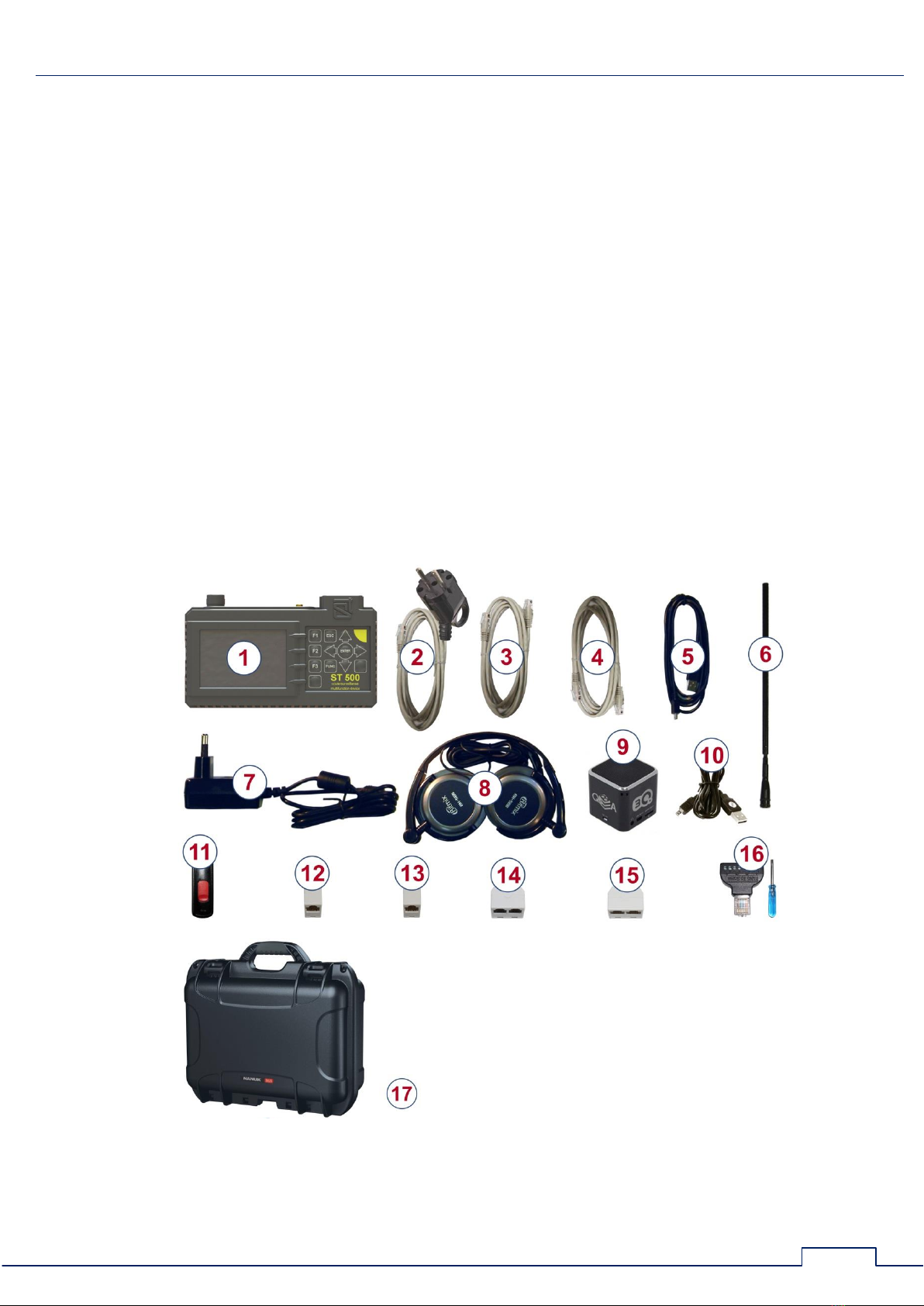
1.2. SPECIFICATION
1.
Main Unit……………………………………………………………………………………………………………………
1 pcs.
2.
Adapter for connecting the main unit to electric mains…………………….……………………
1 pcs.
3.
Cable for connecting the main unit to telephone line sockets….……………………………
1 pcs.
4.
Cable for connecting the main unit to low current sockets……………………………………
1 pcs.
5.
Cable for connecting the main unit to a PC's USB …………………………………………………
1 pcs.
6.
Telescopic antenna……………………………………………………………………………………………………
1 pcs.
7.
Charger………………………………………………………………………………………………………………………
1 pcs.
8.
Headphones………………………………………………………………………………………………………………
1 pcs.
9.
Test sound source…………………………………………………………………………….………………………
1 pcs.
10.
Charger cable for the test sound source……………………………………….…………………………
1 pcs.
11.
USB flash drive………………………………………………………………………………………………….………
1 pcs.
12.
Coupler (RJ11)……………………………………………………………………… ………………………….………
1 pcs.
13.
Coupler (RJ45)……………………………………………………………………………………….………….………
1 pcs.
14.
1x2 splitter (RJ11)…………………………………………………………………………………….………..……
1 pcs.
15.
1x2 splitter (RJ45)……………………………………………………………………………………………………
1 pcs.
16.
Adapter for connecting a multicore cable and Screwdriver……………………………………
1 pcs.
17.
Case…………………..…………………………………………………………………………………………………..…
1 pcs.
The numbers above correspond to those in fig.1.
Fig.1
ST 500 "Piranha" Operation Manual: General Information
5
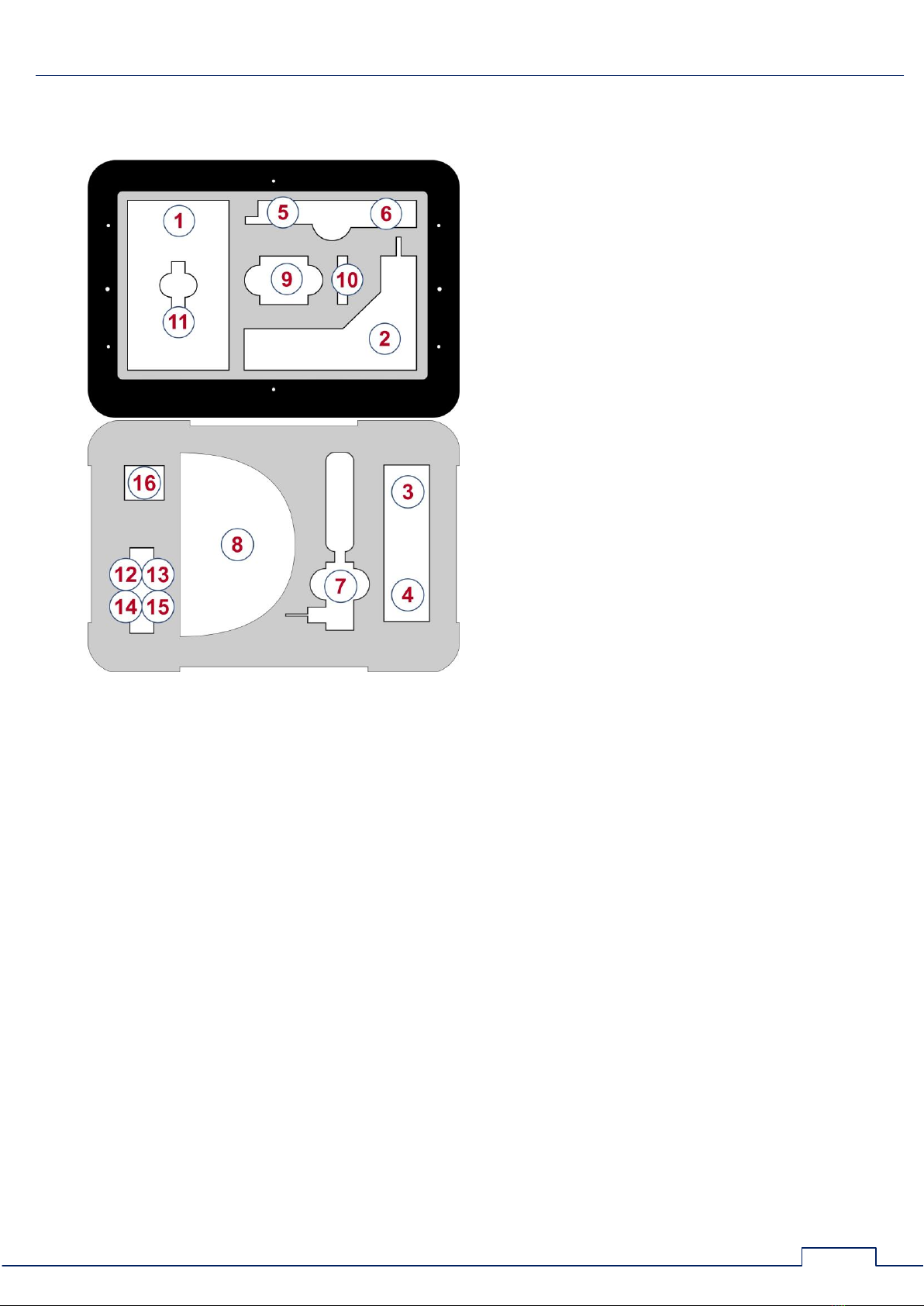
For transportation and storage of the device, the NANUK 915 shock- and moisture-proof plastic
case is used. All the items in the bundle are housed in the two panels within the case.
Upper case panel
Lower case panel
In the placement scheme above, the numbers assigned to items in the ST 500 bundle are the
same as in 1.2.1.
1.3. DESCRIPTION OF SPECIFICATION ITEMS
1.3.1. MAIN UNIT WITH ELECTRONIC SWITCH
Main unit functions:
analysis of the incoming signals,
control of connection schemes to the tested multiwire lines,
data display,
control of operation modes.
Components of the main unit:
signal processing module,
electronic switch,
display module,
power supply module,
controls.

ST 500 "Piranha" Operation Manual: General Information
6
The appearance of the main unit is shown in fig.2.
Fig.2
Number in fig.2
Marking on the device
Element description
1
Display
2
Keyboard
F1-F4
Hotkeys
ESC
Cancellation (return) key
FUNC
Key to enable additional functions
ENTER
Confirmation key
MODE
Main menu key
3
Power switch and volume control
4
PHONES
Headphone socket

ST 500 "Piranha" Operation Manual: General Information
7
Number in fig.2
Marking on the device
Element description
5
Sensor of the IR DETECTOR
6
ANT
Antenna socket of the SELECTIVE HF DETECTOR
7
INPUT
Electronic switch input
8
Prop
9
Info shield with serial number
10
Inbuilt speaker
11
Charger connected indicator
12
Charger socket
13
Mini-USB for PC connection
1.3.2. ELECTRONIC SWITCH
The device is equipped with an inbuilt electronic switch for a more efficient testing of multiwire
cables.
The automated and manual control of the electronic switch allow engaging all possible paired
combinations of cores in a multicore cable connected to the electronic switch (via RJ45 socket,
fig.2, 7). While testing electric mains, control of the electronic switch is disabled.
1.3.3. ADAPTER FOR CONNECTING TO ELECTRIC MAINS
The adapter is intended for connecting the main unit to electric mains equipped with European
standard sockets (fig.1, 2). A LED indicator in the plug shows if the line is powered. The adapter
cable is equipped with an RJ45 connector, with only the first and second pins are engaged, and
the rest are disabled.
1.3.4. CABLE FOR CONNECTING TO COMPUTER SOCKETS (RJ45)
The cable is used for connecting the main unit to a computer line equipped with standard RJ45
connectors.
The cable (fig.1, 4) is a standard patch cord.
1.3.5. CABLE FOR CONNECTING TO TELEPHONE SOCKETS (RJ11)
The cable is used for testing telephone lines equipped with 6P4C sockets. The cable (fig.1, 3) is
equipped with 8P8C (RJ45) and 6P4C connectors. In the RJ45 connector, the four central pins
(## 3-6) are engaged, while the four side ones (## 1, 2, 7, 8) have no connections.
1.3.6. ADAPTER FOR CONNECTING A MULTICORE CABLE
The adapter (fig.1, 16) is used for connecting to raw-ended (not fitted with connectors) low
current cables. While connecting a raw-ended twisted pair cable, it is advised to observe the
wiring color scheme (Supplement #3, 12.3.2).

ST 500 "Piranha" Operation Manual: General Information
8
1.3.7. TEST SOUND SOURCE
Purpose of the test sound source (fig.1, 9):
emission of a sound signal (whose correlation with the reception on ST 500 means that
there is an active eavesdropping device nearby making unencoded transmissions)
forced activation of VOX-activated eavesdropping devices
location of the detected eavesdropping devices
creation of a "masking noise" on the site during search operation
playback from external sources connected through line-in
As the test sound source, an MP3-player/speaker is used. Test sound files are stored on the
USB flash drive (fig.1 11). The user can record sound files of his own making that are better
suited to a given search task. A standard cable is used for charging (fig.1, 10).
1.3.8. MINI-USB CABLE
The cable (fig.1, 5) is used for connecting the main unit to a PC's USB-port.
1.3.9. SPLITTERS, ADAPTERS, AND CONNECTOR CABLES
A set of splitters and connecting cables is supplied with ST 500, that are used for testing
various types of cabling and circuits. Their use is described in Section 5 of this manual:
CONNECTING ST 500 TO CABLING
1.3.10. USB FLASH DRIVE
The USB flash drive contains pre-recorded test sounds for the test sound source, this Manual,
and "ST 500" software.
1.4. POWER SUPPLY
The device is only powered from an inbuilt battery whose charge status is shown in the status
bar (fig.5, 2). A fully charged battery provides 7 hours of non-stop operation.
The battery is charged with the aid of a charger unit (fig.1, 7) plugged into the socket on the
side of the Device (fig.2, 12). The charger is connectable to 220 V/50 Hz mains.
During charging a LED on the side of the Device (fig.2, 11) will be lit red. Full charging time is
up to 7 hours. Upon charging, the LED will change its light to green.
D O N O T A T T E M P T C H A R G I N G T H E D E V I C E D U R I N G O P E R A T I O N !

ST 500 "Piranha" Operation Manual: General Information
9
1.5. TECHNICAL SPECIFICATIONS
Selective HF Detector:
operative frequency range, MHz
20-6000
passband, MHz
1 or 20
impedance, Ohm
50
rate of scanning, GHz/sec
18
bandpass flatness, dB
±6
minimum detection level, dB
-70
dynamic range, dB
50
IR Detector:
spectral range, µm
0.75…1.1
detection passband, MHz
5
field-of-view angle, degrees
±20
minimum detectable power, W/Hz½
10-13
Wired Receiver:
operative frequency range, MHz
0.1-180
whole range scanning time, sec
2
minimum detection level, dBm
-50…-75
dynamic range, dB
50
impedance, Ohm
100
demodulation type
AM, FM
input filter passband, kHz
180
maximum voltage on the circuit, V
250(AC), 60(DC)
Low Frequency Amplifier:
frequency range, Hz
20 - 25000
impedance, kOhm
200
gain, times
1,2,5,10,20,50,100
max voltage amplitude on the input, V
±60(DC),
±1(AC)
noise spectral density, nV/Hz
3
bias voltage range, V
+30, -30
Power Supply:
inbuilt lithium polymer accumulator battery with voltage, V
3.7
power consumption, W
<1
time of continuous operation at maximum power, hrs
>4
recharging time from a full discharge, hrs
7
Weight and Dimensions:
dimensions of the main unit (length, width, height), mm
165 x 100 x 40
mass of the main unit, kg
0.470
package dimensions (length, width, height), mm
390 x 310 x 170
full package mass, kg
4
ST 500 "Piranha" Operation Manual: Interface Options
10
2. INTERFACE OPTIONS
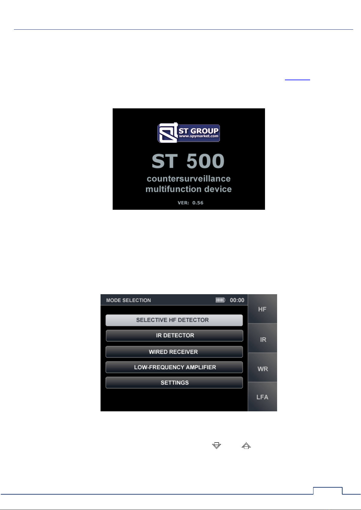
2.1. TURNING THE DEVICE ON/OFF
The Device is turned on/off with the pwer switch and volume control button (fig. 2, 3). When
turned on, the display will show a screen (fig.3) with the ST Group Ltd. logo, name of the Device,
and firmware version number.
Fig.3
Press any key to go to the main menu of device.
2.2. MAIN MENU
One of the four operation channels, or the service mode "SETTINGS", can be selected from the
main menu. The main menu screen is shown in fig.4.
Fig.4
To activate channels "SELECTIVE HF DETECTOR", "IR DETECTOR", "LOW FREQUENCY
AMPLIFIER", and "WIRED RECEIVER", with the keys and move the cursor to the
corresponding line and press "ENTER", or use the hotkeys ("F1", "F2", "F3", "F4", respectively).
Through the "SETTINGS" menu item, system settings can be accessed.
ST 500 "Piranha" Operation Manual: Interface Options
11
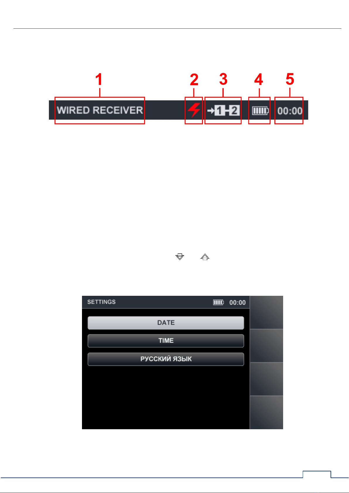
2.3. STATUS BAR
In the upper part of the Device's screen is a status bar shown in fig.5
Fig.5
In fig.5:
1
-
active channel
2
-
electric mains sign
3
-
pair of wires connected
4
-
battery charge sign
5
-
current time (hh:mm)
2.4. "SETTINGS"SERVICE MODE
This SETTINGS mode is intended for setting the date, time and interface language (Russian or
English).
To enter the settings mode, using the keys and select "SETTINGS" in the main menu
and press "ENTER".
To exit SETTINGS mode to the main menu, press "ESC". Any confirmed changes will be saved
upon exiting this mode or deactivating the device. The "SETTINGS" screen is shown in fig.6.
Fig.6
ST 500 "Piranha" Operation Manual: Interface Options
12
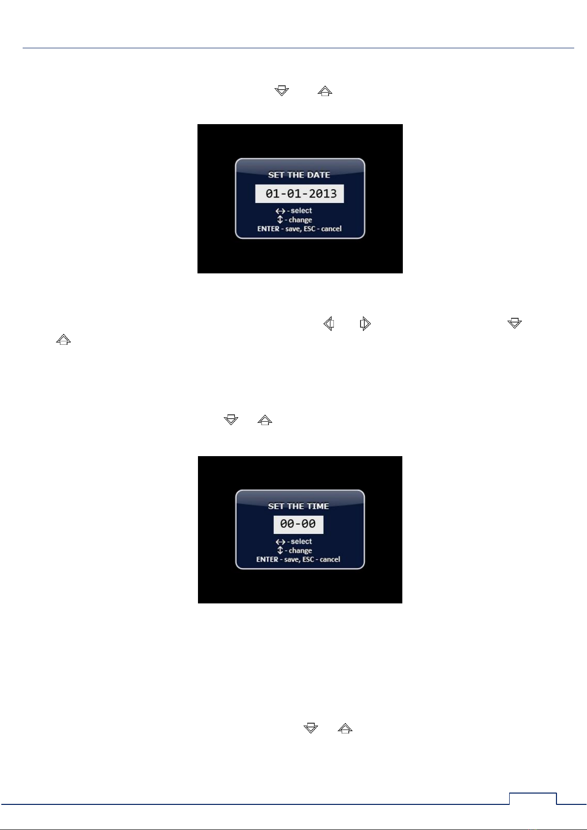
2.4.1. SETTING THE DATE
In order to set the date, use the keys and to select "DATE" in the menu and press
"ENTER". The following screen (fig.7) will appear.
Fig.7
The date format is "DD/MM/ YYYY". Use the keys and to select "DAY", then use and
to set the desired value. Proceed in the same way to set "MONTH" and "YEAR". Use "ENTER"
to confirm changes. Use "ESC" to go back to "SETTINGS". To exit the SETTINGS mode without
saving changes, press "ESC".
2.4.2. SETTING THE TIME
In order to set the time, use or to select "TIME" in the "SETTINGS" menu and press
"ENTER". The following screen (fig.8) will appear, with time in the format "HH/MM".
Fig.8
The time can be set in the same way as the date (3.4.1). Use the "ENTER" to confirm changes.
Use "ESC" to go back to "SETTINGS". To exit the SETTINGS mode without saving changes, press
"ESC".
2.4.3. SETTING THE LANGUAGE
In order to set the interface language, using or select "LANGUAGE" in the menu and
press "ENTER". The interface language will be changed from Russian to English. To set Russian
again, select "РУССКИЙ ЯЗЫК" in the menu and press "ENTER".

ST 500 "Piranha" Operation Manual: Selective HF Detector Channel
13
3. "SELECTIVE HF DETECTOR" CHANNEL
The "SELECTIVE HF DETECTOR" channel is intended for the detection of analog and digital
wireless (utilizing GSM, LTE, Bluetooth, or WiFi) eavesdropping devices operating in the frequency
range 20 MHz - 6 GHz.
For the reception of radio signals, a telescopic antenna is used (fig.1, 6) that has a spherical
radiation pattern. The antenna is connected to asocket on the upper surface of the device (fig.2, 6).
The channel is activated from the main menu.
The detected signals are analyzed based on:
graphic information (spectrogram, oscillogram, table of signals)
acoustic information (via headphones or inbuilt speaker).
Functional Scheme of the "SELECTIVE HF DETECTOR" Channel
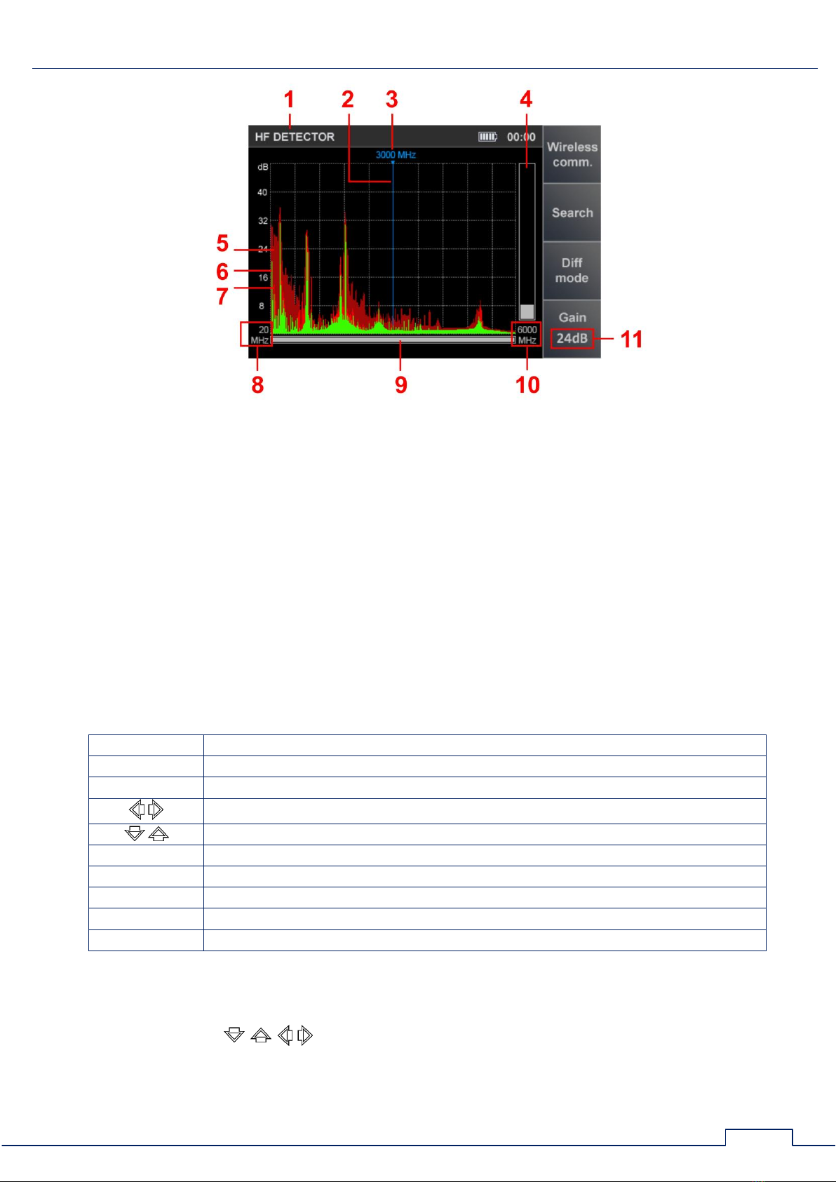
3.1. "PANORAMA" MODE
The "PANORAMA" mode is started by default when the "SELECTIVE HF DETECTOR" channel is
activated. All activity in the frequency band will be shown on the screen (fig. 9).
Functionality:
activating the AUTOMATED mode
activating the "WIRELESS COMMUNICATION" mode
activating the DIFFERENTIAL mode
analyzing the signal at a fixed frequency
setting the gain
adjusting the band limits
ST 500 "Piranha" Operation Manual: Selective HF Detector Channel
14
Fig.9
In fig.9:
1
-
active channel
2
-
screen cursor
3
-
frequency value at the current cursor position
4
-
dynamic bar indicating signal level at the selected frequency
5
-
peak signal value over all cycles at the selected frequency (maroon)
6
-
pulse signals detected in the last measurement cycle (green)
7
-
continuous signals detected in the last measurement cycle (red)
8
-
lower bound of the set frequency range viewing band
9
-
indicator showing the width of the set viewing bar relative to the maximum possible
10
-
upper bound of the set frequency range viewing band
11
-
gain value
Controls:
Key
Action
ESC, MODE
switching to main menu of device
ENTER
turn on "FIXED FREQUENCY ANALYSIS" function
screen cursor positioning
panorama scaling relative to frequency on the marker
F1
activating "WIRELESS COMMUNICATION" mode
F2
activating AUTOMATED mode
F3
activating DIFFERENTIAL mode
F4
gain setting on/off
FUNC
disabled
GAIN SETTING:
1. Press "F4". The "Gain" field will become lighter.
2. Use the keys to set the gain in dB (0, 8, 16, 24, 32, 40). The gain value will
be shown in the corresponding screen field (fig.10).
3. Press "F4". The "Gain" field will become darker.
ST 500 "Piranha" Operation Manual: Selective HF Detector Channel
15
Fig.10
IMPORT A NT! Until the gain setting is completed, other modes and functions are not
available, except for switching to the Main Menu of the device (by pressing "MODE").
3.2. DIFFERENTIAL MODE
In the DIFFERENTIAL mode, signal levels registered during previous scanning cycles in the
"PANORAMA" mode, are set as "0", and only signals in excess of "0" will be shown on the screen
(differential spectrum).
The DIFFERENTIAL mode can be used for isolating the signals from sources within the
inspected premises, from external signals.
The DIFFERENTIAL mode can be activated from the "PANORAMA" mode (fig.9) by pressing
"F3". The "F3" key field will become highlighted.
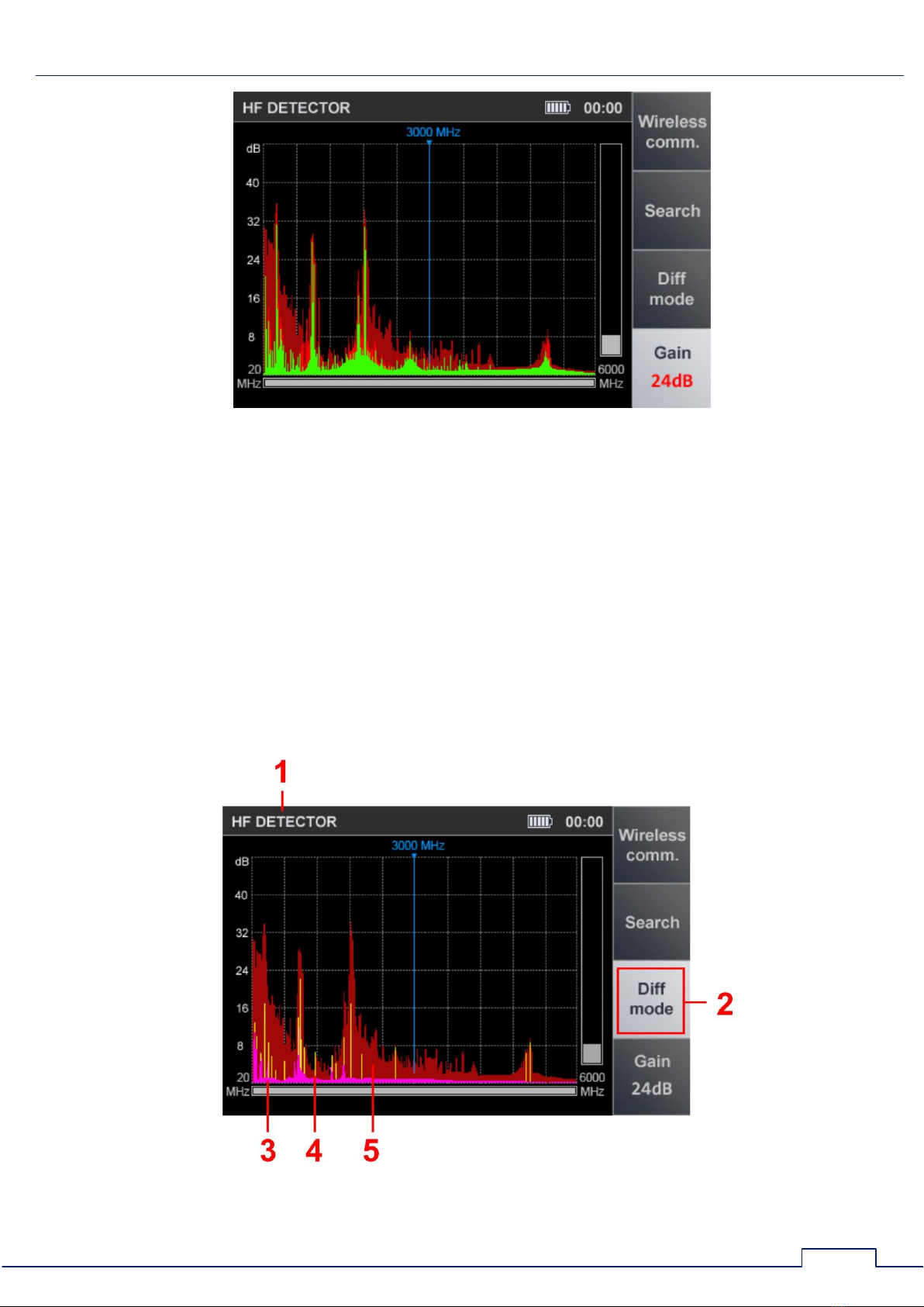
Upon activating the DIFFERENTIAL mode, the screen will look as shown in fig.11.
Fig.11

ST 500 "Piranha" Operation Manual: Selective HF Detector Channel
16
In fig.11:
1
-
active channel
2
-
DIFFERENTIAL mode highlighted as currently active
3
-
constant differential signal registered during the last scanning cycle (lilac)
4
-
pulse differential signal registered during the last scanning cycle (yellow)
5
-
peak signal level at the given frequency over all cycles (maroon)
Functionality:
activating the AUTOMATED mode
activating the "WIRELESS COMMUNICATION" mode
analyzing the signal at a set frequency
setting the gain
adjusting the band limits (zoom)
Switching off the DIFFERENTIAL mode (return to the "PANORAMA" mode) is performed by
pressing the "F3". The "F3" key field will become darker. Gain values and span set in
DIFFERENTIAL mode are saved.
3.2.1. "FIXED FREQUENCY ANALYSIS" FUNCTION
This feature is intended for researching signals detected in the "PANORAMA" or DIFFERENTIAL
mode. To activate it from either of said modes, select the signal of interest using and and
press "ENTER". The screen will look as shown in fig.12 below.
Fig.12

ST 500 "Piranha" Operation Manual: Selective HF Detector Channel
17
In fig.12:
1
-
active detection channel
2
-
signal level at the selected frequency (at cursor position)
3
-
"SET "0" active
4
-
selected passband (1 MHz or 20 MHz)
5
-
OSCILLOSCOPE active
Functionality:
tuning to the frequency of the detected signal
passband selection (1 MHz or 20 MHz);
listening to a demodulated signal
analyzing the signal with oscilloscope
locating the signal source with power method
Controls:
Key
Action
MODE
switching to the main menu of device
ENTER, ESC
turning off "FIXED FREQUENCY ANALYSIS " function
screen cursor positioning
F1
turning on/off "SET "0" function
F2
passband selection (1 MHz or 20 MHz)
F3
turning on OSCILLOSCOPE
F4
turning on/off gain setting
FUNC
disabled
To turn off "FIXED-FREQUENCY MONITORING" function, press "ENTER" or "ESC". The device
will switch back to the mode, from which the function was activated ("PANORAMA" or
DIFFERENTIAL mode).
3.2.2. "SET "0" FUNCTION
This function helps locate the source of a detected signal. It can be especially helpful in finding
the sources of powerful signals that make the screen levels go off-scale even at minimum gain.
Ways of locating eavesdropping devices are described in more detail in 9.1.4.
When "SET "0" is used, the signal level at current frequency is set as "0", and only the level
differences are displayed.
To turn on the "SET "0", press "F1". The "F1" key field will become lighter.
When using the "SET "0" function, it is possible to:
change the passband ("F2")
turn on the oscilloscope ("F3")
change the gain ("F4")
To turn off the "SET "0", press "F1" again. The "F1" field will become darker.
ST 500 "Piranha" Operation Manual: Selective HF Detector Channel
18
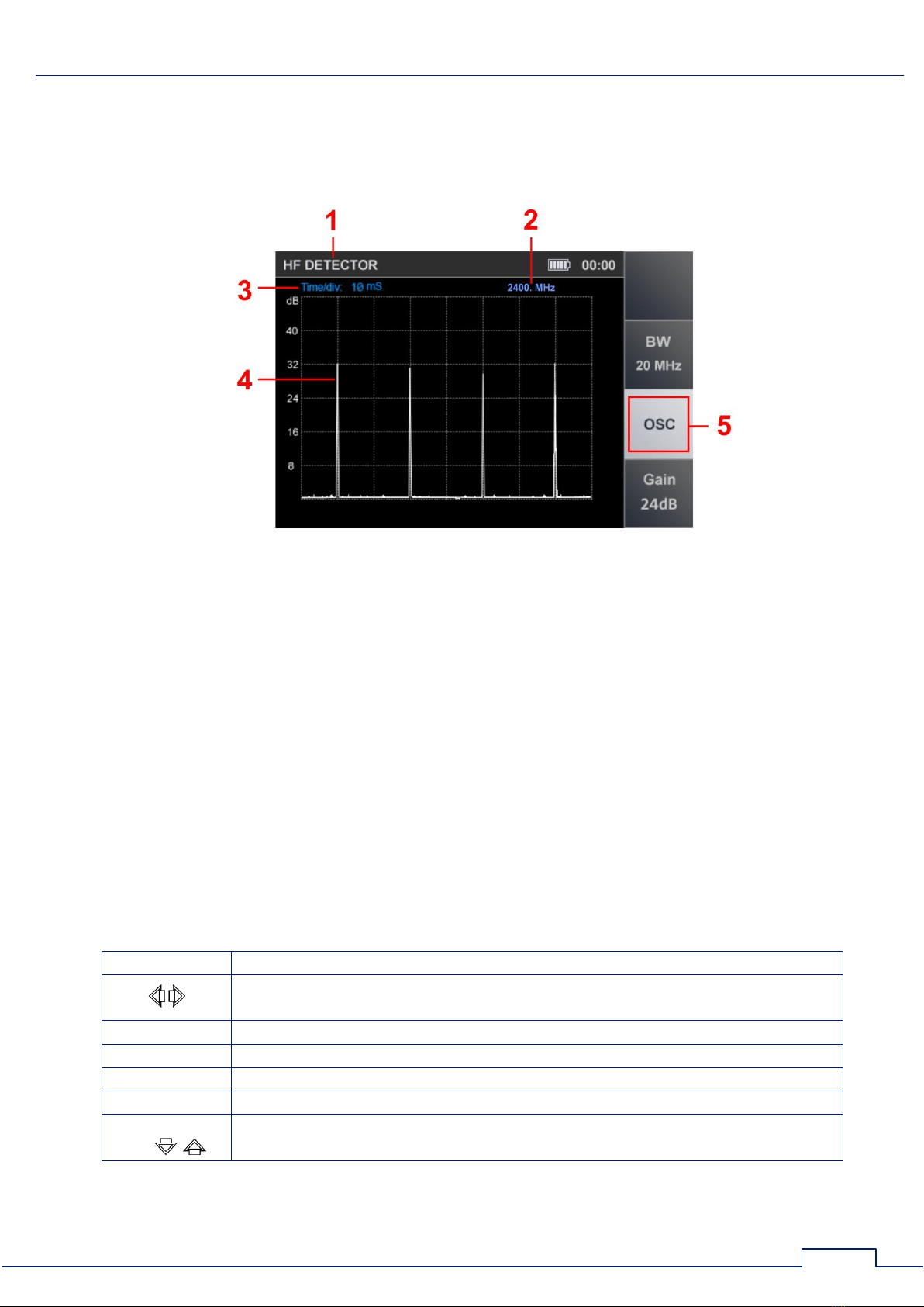
3.2.3. OSCILLOSCOPE
To activate the OSCILLOSCOPE, after switching on the "FIXED FREQUENCY ANALYSIS"
function, press the "F3". The "OSC" field will become lighter. The screen will look as shown in
fig.13 below.
Fig.13
In fig.13:
1
-
active detection channel
2
-
selected frequency value
3
-
set division value of the time axis
4
-
oscillogram of a demodulated signal at the selected frequency
5
-
on indication of the inclusion of the OSCILLOSCOPE
Functionality:
determining the time parameters of a demodulated signal
setting the division value of the time axis
passband selection
gain adjustment
Controls:
Key
Action
selecting the division value of the horizontal sweep
100µS/200µS/500µS/1mS/2mS/5mS/10mS
F2
passband selection (1 MHz or 20 MHz)
F3, ESC
turning off OSCILLOSCOPE
F4
activating gain adjustment
MODE
switching to main menu of device
FUNC ENTER
F1
disabled
To turn off the OSCILLOSCOPE press "F3" or "ESC".
ST 500 "Piranha" Operation Manual: Selective HF Detector Channel
19
3.3. AUTOMATED MODE
The AUTOMATED mode is used to register signals whose amplitudes exceed the adaptive
detection threshold. It is activated from the DIFFERENTIAL or "PANORAMA" mode by pressing "F2".
Search for signals is performed within set frequency limits, based on the data obtained in the
DIFFERENTIAL mode (if the AUTOMATED mode has been activated from the DIFFERENTIAL mode).
Each detected signal is assigned one of the three categories, "NON-THREAT", "THREAT", or
"UNKNOWN". By default, those are:
"NON-THREAT" –signals of base stations of mobile telecommunication networks
"THREAT" –signals of mobile digital communication devices
"UNKNOWN" –all the remaining signals.
With the help of ST 500 ST 500 software (8.6.1), bands can be assigned "THREAT" or "NON-
THREAT" status, so that the received signals will be accordingly marked with color, depending on
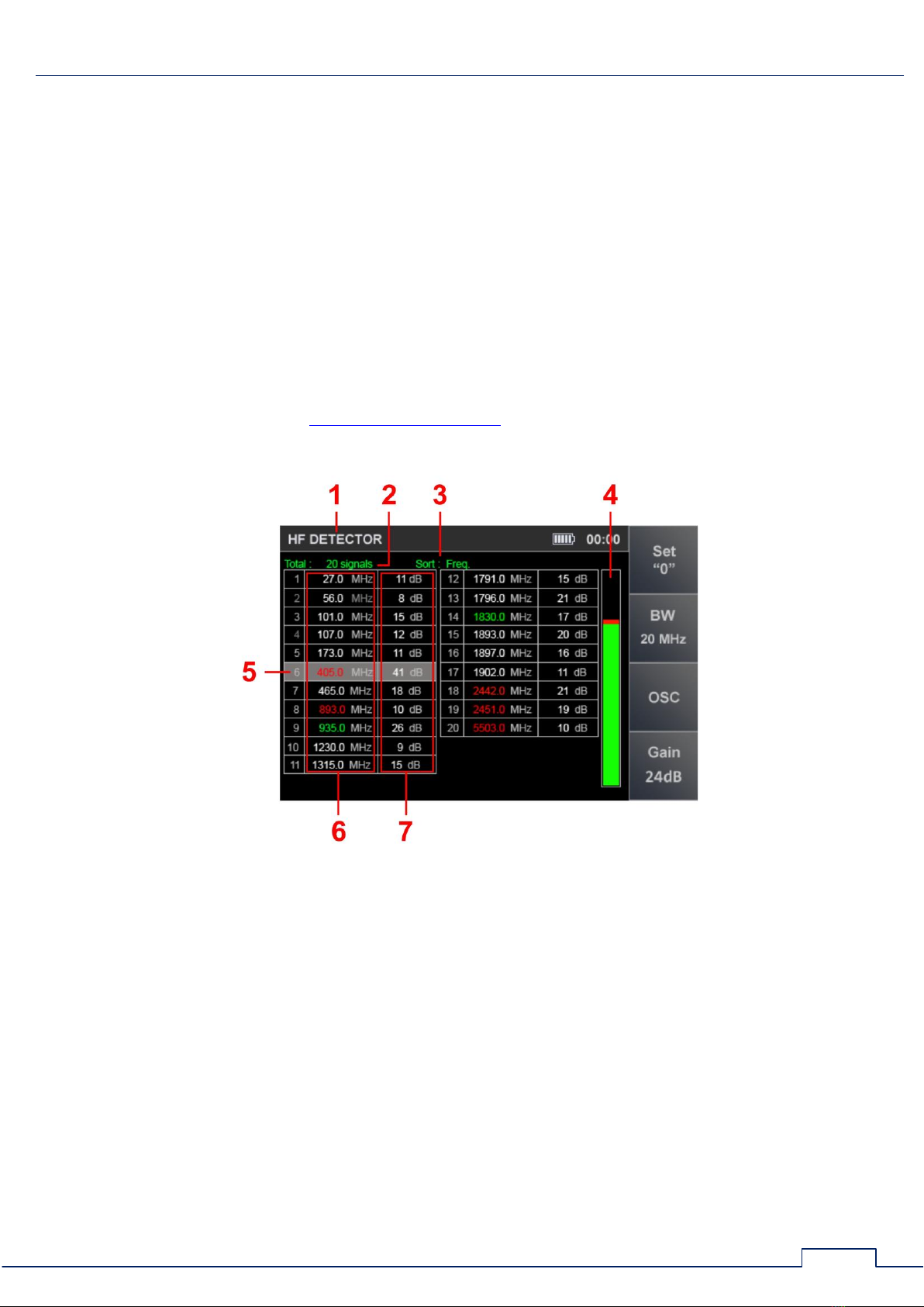
the frequency band they are in. Upon mode activation, the screen will look as shown in fig.14.
Fig.14
In fig.14:
1
-
active channel
2
-
number of the detected signals
3
-
data sorting type (by level or frequency)
4
-
signal level at the current cursor position
5
-
current table row
6
-
frequency values of the detected signals
7
-
levels of the detected signals
In fig.14 frequency values of the detected signals are marked with different colors:
"THREAT" signals - red
"NON-THREAT" signals - green
"UNKNOWN" signals - white
Table of contents
Other ST Group Measuring Instrument manuals


