manuals.online logo
Brands
  1. Home
  2. •
  3. Brands
  4. •
  5. LEYBOLD
  6. •
  7. Measuring Instrument
  8. •
  9. LEYBOLD I-Measuring Amplifier D User manual

LEYBOLD I-Measuring Amplifier D User manual

Physik Chemie ⋅Biologie Technik LEYBOLD DIDACTIC GMBH
12/96-Hu/Brs-
Gebrauchsanweisung 532 00
Instruction Sheet
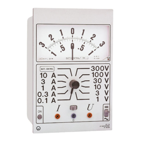
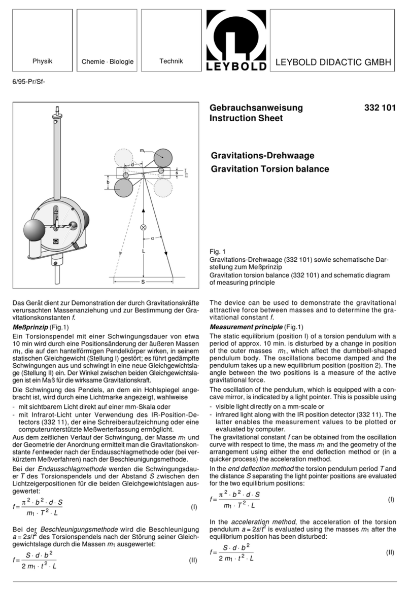
The I-measuring amplifier D is a DC amplifier; when used in
conjunction with a voltmeter as the display unit, it serves to
measure currents, voltages and charges.
1 Safety notes
Literature:
Book: I-Measuring Amplifier D (532 032)
2 Scope of supply, description, technical data
2.1 Scope of supply, description
11
Mains switch with on-indicator lamp
22
BNC input for voltage measurements
33
BNC input for current and charge measurements
44
Ground socket of input, connected to protective-earth con-
ductor
55
Zero-key. The input of the measuring amplifier is grounded
66
Pair of output sockets for connecting a voltmeter measu-
ring range 0.3 V DC to 10 V DC; see table 2)
77
Zero-point adjuster
Der I-Meßverstärker D istein Gleichstromverstärker, der inVer-
bindung mit einem Voltmeter als Anzeigegerät zur Messung
von Strömen, Spannungen und Ladungen dient.
1 Sicherheitshinweise
Literaturhinweis:
Buch I-Meßverstärker D (532 031)
2 Lieferumfang, Beschreibung, Technische Daten
2.1 Lieferumfang, Beschreibung
11
Netzschalter mit Betriebsanzeigelampe
22
BNC-Eingang für Spannungsmessungen
33
BNC-Eingang für Strom- und Ladungsmessungen
44
Erdungsbuchse des Eingangs, mit Schutzleiter verbunden
55
Nulltaste. Der Eingang des Meßverstärkers wird auf Masse
gelegt.
66
Ausgangsbuchsenpaar zum Anschluß eines Voltmeters
Meßbereich 0,3 V
(
bis 10 V
(
; s. Tabelle 2)
77
Nullpunktverschiebungs-Steller
I-Meßverstärker D
I-Measuring Amplifier D
Fig. 1
•Bei einer Netzanschlußspannung von 115 V
"
Gerät ge-
mäß Abschnitt 4.2 umrüsten.
•Nur mit nicht berührungsgefährlichen Spannungen arbei-
ten.
•Meßbereichswahlschalter
8
zunächst auf unempfindlich-
sten Bereich einstellen, insbesondere bei unbekannter
Größe des Meßwertes.
•Brummsignale über 10 VSam Ausgang
8
verfälschen das
Meßergebnis. Im Zweifelsfall (z.B. mit einem Oszilloskop)
prüfen!
•Eingangsströme größer als etwa 5 mA (Urspannung
≥500 V) übersteuern den Verstärker. Gegebenenfalls Vor-
widerstand benutzen! (s. Abschnitt 3.4)
•Zur Vermeidung von Falschmessungen Bedienungshin-
weise unter 3.2 bis 3.3 unbedingt beachten.
•To use the device with a mains voltage of 115 V AC, con-
vert it as described in section 4.2.
•Use only with non-hazardous contact voltages.
•Always start with the measuring-range selector
8
swit-
ched to the most insensitive range, particularly when the
magnitude of the measured value is unknown.
•Hum signals above 10 Vpat output
8
falsify the measuring
result. You may need to check this (e.g. with an oscillo-
scope)!
•Input currents greater than approx. 5 mA (e.m.f. ≥500 V)
overdrive the amplifier. Use a resistor if necessary!(see
section 3.4).
•Always observe the instructions in sections 3.2 to 3.3 to
avoid falsified measurements.
88
Meßbereichs-Wahlschalter
99
Meßkabel BNC/4mm (575 24) mit separatem Anschluß
(4-mm-Stecker) für Abschirmung
Impedanz: 50 Ω
Kapazität: 120 pF
Länge: 1,2 m
2.2 Technische Daten
Strom-
bereiche Eingangs-
widerstand Spannungs-
bereiche Eingangs-
widerstand Ladungs-
bereiche Eingangs-
widerstand
10-6 A 105ΩΩ 10-2 V 109ΩΩ 10-6 As 105ΩΩ
10-7 A 105ΩΩ 102V 109ΩΩ 10-7 As 105ΩΩ
10-8 A 105ΩΩ 101V 109ΩΩ 10-8 As 105ΩΩ
10-9 A 105ΩΩ 100V 109ΩΩ 10-9 As 105ΩΩ
10-10 A 105ΩΩ 10-1 V 109ΩΩ
10-11 A 105ΩΩ
Tabelle 1
Alle Angaben beziehen sich auf eine Ausgangsspannung von
1 V. Das Gerät ist jedoch übersteuerbar bis zu einer Aus-
gangsspannung von 10 VS.
Eingang: je eine BNC-Buchse für Strom-/Ladungsmes-
sung und Spannungsmessung. Masse galva-
nisch über Leiterplatte mit Schutzleiter verbun-
den.
Ausgang: zwei 4-mm-Buchsen, Quellwiderstand 100 Ω
Meßgenauigkeit: typisch 3 % bei Strom-/Ladungsmes-
sung
5 % bei Spannungsmessung
Nullpunktstabilität: 0,1 %
Verstärkungsstabilität: Fehler < 1 %
Netzanschlußspannung: 230 V 50/60 Hz auf 115 V
"
um-
rüstbar (s. Abschnitt 4.2)
Leistungsaufnahme: 6 VA
Sicherungen: T 0,125 B bei 230 V
"
T 0,2 B bei 115 V
"
Abmessungen: 20 cm x 21 cm x 23 cm
Masse: 2 kg
3 Bedienung
3.1 Inbetriebnahme, Auswahl des Anzeigeinstrumentes
Voltmeter am Ausgang
6
anschließen. Als Anzeigegerät sind
alle Gleichspannungsmeßinstrumente mit einem Innenwider-
stand von mehr als 3 kΩund mindestens einem Meßbereich
zwischen 0,3 V und 3 V (maximal 10 V) geeignet, z.B.:
Gerät Kat. Nr. Meßbereiche
0,3 V 1 V 3 V 10 V
Drehspul-Meßinstrument P 531 80 X X
Demo-Multimeter 531 911
oder 915 XXXX
AV-Meßgerät 531 94 X X X
Oszilloskop, z.B.: 575 21 X X X X
XY-Yt-Schreiber, z.B.: 575 663 X X
Yt-Schreiber, z.B.: 575 702 X X
für computerunterstütztes
Experimentieren:
z.B. CASSY-E 524 007 X X X X
Tabelle 2
Der zu messenden Größe ist gelegentlich noch als Folge man-
gelhafter Abschirmung (versuchsbedingt) ein 50-Hz-Signal
überlagert, das mit verstärkt wird, aber nicht angezeigt werden
soll.
Die oben angegebenen Meßinstrumente mitteln (erforderli-
chenfalls mit parallel geschaltetem Kondensator) einen sym-
88
Measuring range selector
99
Screened cable BNC/4-mm (575 24) with separate con-
nector (4-mm plug) for screen
Impedance: 50 Ω
Capacitance: 120 pF
Length: 1.2 m
2.2 Technical data
Current
ranges Input
resistance Voltage
ranges Input
resistance Charge
ranges Input
resistance
10-6 A 105ΩΩ 10-2 V 109ΩΩ 10-6 As 105ΩΩ
10-7 A 105ΩΩ 102V 109ΩΩ 10-7 As 105ΩΩ
10-8 A 105ΩΩ 101V 109ΩΩ 10-8 As 105ΩΩ
10-9 A 105ΩΩ 100V 109ΩΩ 10-9 As 105ΩΩ
10-10 A 105ΩΩ 10-1 V 109ΩΩ
10-11 A 105ΩΩ
Table 1
All data refer to an output voltage of 1 V. However, the device
can be overdriven up to an output voltage of 10 Vp.
Input: one BNC socket each for current/charge measure-
ment and voltage measurement. Ground electri-
cally connected to PE conductor via PC board.
Output: two 4-mm sockets, source resistance 100 Ω
Measuring accuracy: typical 3 % for current/charge meas-
urement
5 % for voltage measurement
Zero-point stability: 0.1 %
Gain stability: error < 1 %
Mains connection voltage: 230 V 50/60 Hz, convertible to
115 V AC (see section 4.2)
Power consumption: 6 VA
Fuses: T 0.125 B for 230 V AC
T 0.2 B For 115 V AC
Dimensions: 20 cm x 21 cm x 23 cm
Weight: 2 kg
3Operation
3.1 Putting into operation, selecting the display instrument
Connect a voltmeter at output
6
. All DC measuring instruments
with an internal resistance greater than 3 kΩand at least one
measuring range between 0.3 V and 3 V (maximum 10 V) can
be used, e.g.:
Device Cat. No. Measuring ranges
0.3 V 1 V 3 V 10 V
Moving-coil instrument P 531 80 X X
Demo-multimeter 531 911
or 915 XXXX
AV-meter 531 94 X X X
Oscilloscope, e.g.: 575 21 X X X X
Xy-yt-recorder, e.g.: 575 663 X X
Yt-recorder, e.g.: 575 702 X X
for computer-assisted
experimenting:
e.g. CASSY-E 524 007 X X X X
Table 2
Inadequate screening (due to the experiment conditions) can
result in a 50 Hz signal being superpositioned on the quantity to
be measured; this signal is also amplified, even though its dis-
play is not desired.
The above measuring instruments average a symmetrical hum
to approx. zero (via a parallel-connected capacitor if
necessary). The hum signal at the output may not exceed
10 Vp, as otherwise it is asymmetrically limited and thus causes
2
an erroneous reading. To check this, you may need to connect
an oscilloscope at output
6
.
3.2 Current measurement
Connect the screened cable at BNC input
3
and supply the
measurement signal.
Set the current measuring range on
8
so that (depending on
the measuring instrument) the output signal connected is about
0.3 V to 3 V (maximum 10 V).
The measured value is determined by multiplying the measu-
ring range by the numerical value of the output voltage (measu-
red in volts).
Example: Measuring range: 10-8 A
Output voltage: 1.3 V
Measured value: 1.3 ⋅10-8 A
Important:
- Screen the input as well as possible to avoid input interference,
e.g. from the mains frequency. When conducting stationary cur-
rent measurement, a capacitor, e.g. 0.5 µF (538 04), can be con-
nected parallel to the screened-cable input for smoothing (see
also 3.1).
- Do not disturb the screened cable during the experimentto
prevent charge shifts.
- Isolate the measuring point from other current sources (e.g.
also from the insulation of voltage-bearing leads and the
benchtop) to minimize leakage currents. Compensate any re-
maining input offset currents using the zero-point adjuster on
7
.
3.3 Voltage measurement
Attention:
use only non-hazardous contact voltages (see secti-
on 1)
Connect the measuring lead at BNC input
2
and supply the
measurement signal.
Set the voltage-measuring range on
8
so that (depending on
the measuring instrument) the output signal connected is about
0.3 V to 3 V (maximum 10 V).
The measured value is determined by multiplying the measu-
ring range by the numerical value of the output voltage (measu-
red in volts).
Example: Measuring range: 101V
Output voltage: 0.7 V
Measured value: 7 V
3.4 Charge measurement
Important:
The input current may not be greater than approx. 5 mA, as
otherwise the amplifier is overdriven and the measuring result
is falsified. Therefore, at e.m.f. values greater than 500 V an
additional resistor of e.g. 1 MΩ(for voltages up to 5 kV) must be
connected in front of the amplifier input.
Connect the measuring lead at BNC input
3
and supply the
measurement signal; for e.m.f. values over 500 V, always use
an additional resistor of e.g. 1MΩ.
Set the measuring range so that (depending on the measuring
instrument) the output signal connected is about 0.3 V to 3 V
(maximum 10 V).
The measured value of the charge is determined by multiplying
the selected measuring range by the numerical value of the out-
put voltage (measured in volts).
Example: Measuring range: 10-8 As
Output voltage: 3 V
Measured value: 3 ⋅10-8 As
metrischen Brumm zu Null. Das Brumm-Signal am Ausgang
darf 10 VSnicht überschreiten, weil es sonst unsymmetrisch
begrenzt wird und deshalb zu einer Fehlanzeige führt. Im Zwei-
fel mit Oszilloskop am Ausgang
6
überprüfen.
3.2 Strommessung
Meßkabel am BNC-Eingang
3
anschließen und Meßsignal zu-
führen.
Strom-Meßbereich an
8
so wählen, daß Ausgangssignal (je
nach angeschlossenem Meßinstrument) etwa 0,3 V bis 3 V
(maximal 10 V) beträgt.
Der Meßwert ergibt sich durch Multiplikation des Meßbereiches
mit dem Zahlenwert der (in Volt gemessenen) Ausgangsspan-
nung.
Beispiel: Meßbereich: 10-8 A
Ausgangsspannung: 1,3 V
Meßwert: 1,3 ⋅10-8 A
Wichtig:
- Eingang möglichst abschirmen, um Einstreuungen z.B. der
Netzfrequenz zu vermeiden. Bei stationärer Strommessung
kann zur Glättung ein Kondensator, z.B. 0,5 µF (538 04), par-
allel zum Meßkabeleingang gelegt werden (siehe auch 3.1).
- Meßkabel während der Messung nicht verformen, um La-
dungsverschiebungen zu vermeiden.
- Meßstelle von anderen Stromquellen (z.B. auch von der Iso-
lierung spannungsführender Kabel und Tischplatte) separie-
ren, um Kriechströme zu minimieren. Verbleibende Fehlströ-
me über den Nullpunkt-Stellen an
7
kompensieren.
3.3 Spannungsmessung
Achtung:
Nur mit nicht berührungsgefährlichen Spannungen ar-
beiten (s. Abschnitt 1)
Meßkabel an BNC-Eingang
2
anschließen und Meßsignal zu-
führen.
Spannungs-Meßbereich an
8
so wählen, daß das Ausgangssig-
nal (je nach angeschlossenem Meßinstrument) etwa 0,3 V bis
3 V (maximal 10 V) beträgt.
Der Meßwert ergibt sich durch Multiplikation des Meßbereiches
mit dem Zahlenwert der (in Volt gemessenen) Ausgangsspan-
nung.
Beispiel: Meßbereich: 101V
Ausgangsspannung: 0,7 V
Meßwert: 7 V
3.4 Ladungsmessung
Wichtig:
Der Eingangsstrom darf nicht größer als etwa 5 mA werden,
sonst ist der Verstärker übersteuert und das Meßergebnis wird
verfälscht. Bei Urspannungen über 500 V muß deshalb ein
zusätzlicher Widerstand von z.B. 1 MΩ(für Spannungen bis
5 kV) vor den Verstärkereingang gelegt werden.
Meßkabel am BNC-Eingang
3
anschließen und Meßsignal zu-
führen, bei Urspannungen über 500 V nur über zusätzlichen
Widerstand von z.B. 1MΩ.
Meßbereich so wählen, daß das Ausgangssignal (je nach an-
geschlossenem Meßinstrument) etwa 0,3 V bis 3 V (maximal
10 V) beträgt.
Der Ladungs-Meßwert ergibt sich durch Multiplikation des ge-
wählten Meßbereiches mit dem Zahlenwert der (in Volt gemes-
senen) Ausgangsspannung.
Beispiel: Meßbereich: 10-8 As
Ausgangsspannung: 3 V
Meßwert: 3 ⋅10-8 As
3
LEYBOLD DIDACTIC GMBH ⋅Leyboldstrasse 1 ⋅D-50354 Hürth ⋅Phone (02233) 604-0 ⋅Telefax (02233) 604-222 ⋅ Telex 17 223 332 LHPCGN D
©by LeyboldDidacticGmbH, PrintedintheFederalRepublicofGermany
Technical alterations reserved
4 Sicherungsaustausch,
Netzspannungsanpassung
4.1 Austausch der Primär-Sicherung
Einsatz
a
(mit Fassung für Primärschmelzsicherung
b
und
Reservesicherung
c
) heraushebeln (Fig. 2.1).
Defekte Sicherung
b
durch neue, auf richtigen Sicherungs-
wert überprüfte Sicherung
c
ersetzen (Fig. 2.2).
Neue Sicherung (Wert s. Abschnitt 2) als Reservesicherung
c
einsetzen und Einsatz
a
wieder ein-schieben.
4.2 Umrüsten eines Gerätes auf eine Netzspannung von
115 V
Achtung! Netzstecker ziehen!
Gehäuseschrauben
e
auf der Geräte-Unterseite mit einem
Kreuzschlitzschraubendreher (Größe 2) lösen (Fig. 3.1).
Gerät stellen und Gehäuseoberschale
f
abziehen (Fig. 3.2).
Aus der blauen Steckfassung
g
am Transformator die für
230 V Netzspannung plazierte Leiterplatte
h
herausziehen
(Fig. 3.3).
Platte
h
so drehen, daß der Aufdruck 110 V (für 115 V Netz-
spannung) links unten über der 1 auf der Steckleistenseite der
Steckfassung
g
erscheint (Fig. 3.4).
Platte
h
einschieben und Gehäuse wieder zusammenschrau-
ben.
Primärschmelzsicherung der veränderten Netzspannung an-
passen (s. technische Daten).
Austauschanleitung s. Abschnitt 4.1 (Fig. 2.1 und 2.2).
4 Replacing the fuse, converting the mains
voltage
5 Replacing the primary fuse
Pry out insert
a
with holder for primary fuse
b
and spare fuse
c
(Fig. 2.1).
Replace the defective fuse
b
using a new fuse
c
which has
been checked for the correct rating (Fig. 2.2).
Insert the new spare fuse
c
(see section 2 for the correct ra-
ting) and put the insert
a
back in the device.
5.1 Converting the device for operation with 115 V mains
voltage
Attention: always unplug the device first!
Loosen housing screw
e
on the bottom of the device using a
Philips screwdriver (size 2) (Fig. 3.1).
Turn the device right side up and remove the top housing sec-
tion
f
(Fig. 3.2).
Remove the PC board
h
in the 230 V position from the blue
slot
g
at the transformer (Fig. 3.3).
Turn the board
h
around so that the stamped designation
"110 V" (for 115 V mains voltage) is at the bottom left above the
"1" on the contact side of the plug-in slot
g
(Fig. 3.4).
Insert board
h
and screw the housing back together.
Insert the correct primary fuse for the new mains voltage (see
technical data).
See section 4.1 (Fig. 2.1 and 2.2) for instructions on how to
change the fuse.
Fig. 3. 1 - 3.4
Fig. 2.1 Fig. 2.2

This manual suits for next models

1

Other LEYBOLD Measuring Instrument manuals

LEYBOLD LEYSPEC view Series Instruction manual

LEYBOLD

LEYBOLD LEYSPEC view Series Instruction manual

LEYBOLD 332 101 User manual

LEYBOLD

LEYBOLD 332 101 User manual

LEYBOLD IONIVAC ITR 90 User manual

LEYBOLD

LEYBOLD IONIVAC ITR 90 User manual

LEYBOLD 555 88 User manual

LEYBOLD

LEYBOLD 555 88 User manual

LEYBOLD LEYSPEC view Series User manual

LEYBOLD

LEYBOLD LEYSPEC view Series User manual

LEYBOLD COMBIVAC CM 31 User manual

LEYBOLD

LEYBOLD COMBIVAC CM 31 User manual

LEYBOLD Phoenix Mobilis User manual

LEYBOLD

LEYBOLD Phoenix Mobilis User manual

LEYBOLD 531 94 User manual

LEYBOLD

LEYBOLD 531 94 User manual

LEYBOLD 666 413 User manual

LEYBOLD

LEYBOLD 666 413 User manual

Popular Measuring Instrument manuals by other brands

Quantel Ultra quick start guide

Quantel

Quantel Ultra quick start guide

Delta OHM HD 9221 instruction manual

Delta OHM

Delta OHM HD 9221 instruction manual

Megger DLRO-H200 user guide

Megger

Megger DLRO-H200 user guide

Diablo AVI-CR user manual

Diablo

Diablo AVI-CR user manual

Nidec PG-100N Series instruction manual

Nidec

Nidec PG-100N Series instruction manual

Black Box FOOBL manual

Black Box

Black Box FOOBL manual

HART Prosonic S FMU90 operating instructions

HART

HART Prosonic S FMU90 operating instructions

Co2meter SAN-20 user manual

Co2meter

Co2meter SAN-20 user manual

Maschinenfabrik Reinhausen MESSKO MLOG IM50 operating instructions

Maschinenfabrik Reinhausen

Maschinenfabrik Reinhausen MESSKO MLOG IM50 operating instructions

KEPCO 520K Series instructions

KEPCO

KEPCO 520K Series instructions

MEI KC-326B instructions

MEI

MEI KC-326B instructions

UEi DL569 instruction manual

UEi

UEi DL569 instruction manual

TPI SP597 instruction manual

TPI

TPI SP597 instruction manual

YOKOGAWA IS8000 user manual

YOKOGAWA

YOKOGAWA IS8000 user manual

ATI Technologies Q46 Series Communications manual

ATI Technologies

ATI Technologies Q46 Series Communications manual

Kane KANE458s manual

Kane

Kane KANE458s manual

Televes 593961 quick guide

Televes

Televes 593961 quick guide

PRECISION DIGITAL Javelin D PD644 Specification Datasheet

PRECISION DIGITAL

PRECISION DIGITAL Javelin D PD644 Specification Datasheet

manuals.online logo
manuals.online logoBrands
  • About & Mission
  • Contact us
  • Privacy Policy
  • Terms and Conditions

Copyright 2025 Manuals.Online. All Rights Reserved.