AD-ICD 2 Configuring the ICD adapter
5/15
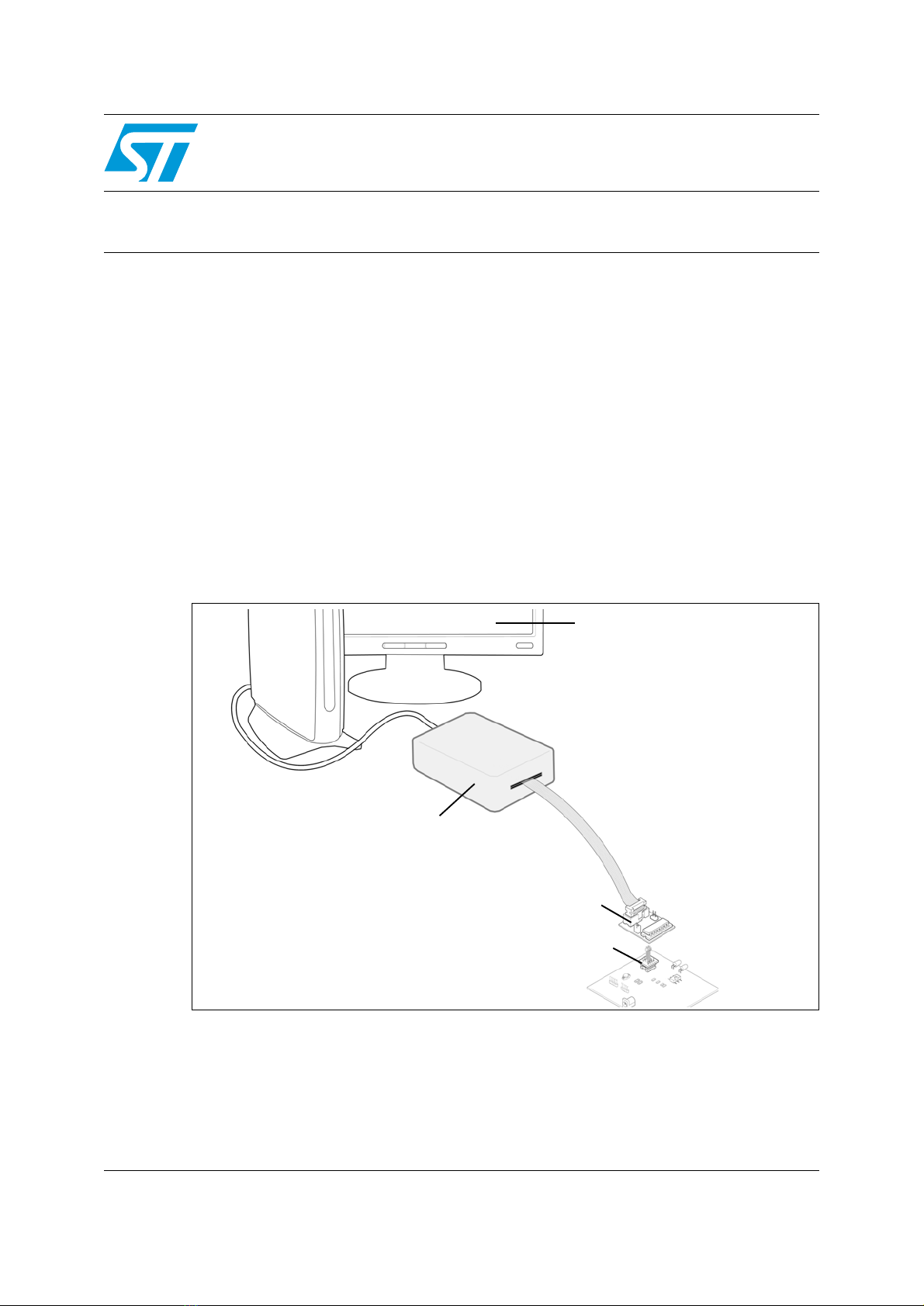
2 Configuring the ICD adapter
The following sections provide instructions about configuring your ICD adapter for
In-circuit
debugging
or to
Run the application in standalone mode
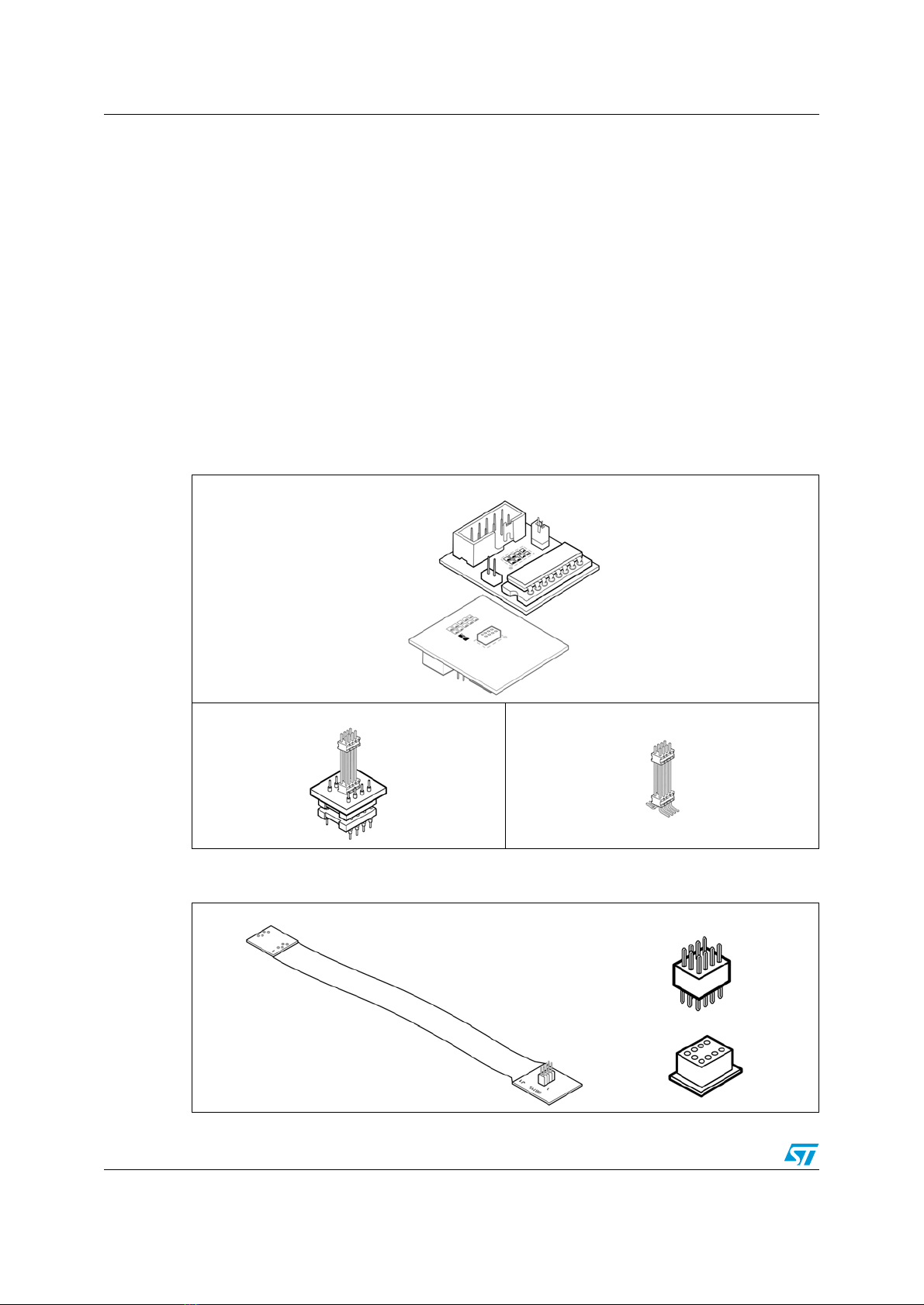
. Delivered from the factory, the AD-
ICD/DS8Z-01 is configured as follows:
Caution: When configuring the ICD adapter, make sure that the ICD tool and application board (if
connected to the adapter) are powered off.
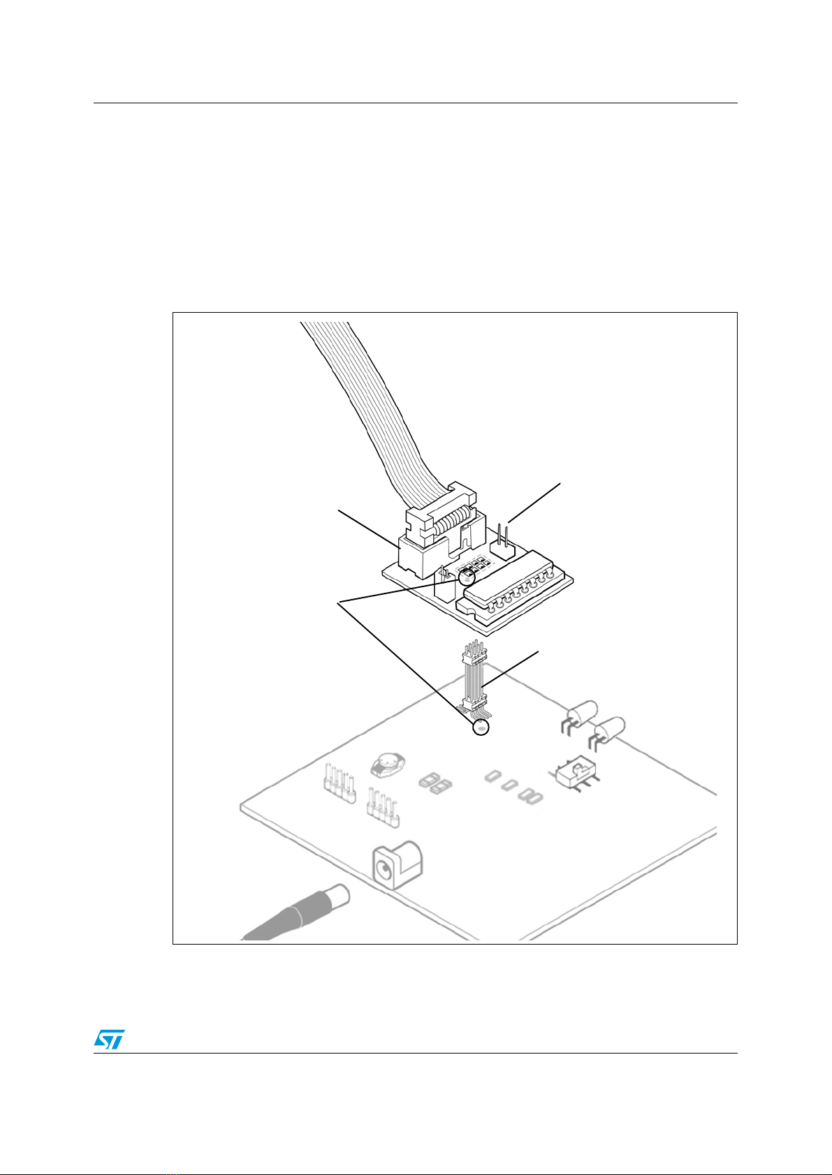
2.1 In-circuit debugging
ICD On jumper (TP1)
When in-circuit debugging the target application via the 10-pin ICC connection, the ICD On
jumper (TP1) must be fitted to allow the interface with an in-circuit debugging tool and the
host PC. During in-circuit debugging, the
RST/PA3 On
jumper (TP2) must not be fitted.
Table 1. Default configuration of the AD-ICD/DS8Z-01 from factory
Identifier on
ICD adapter Configuration Purpose
Jumpers TP1 Fitted Allow connection for in-circuit
debugging/programming
TP2 Not fitted Run application in standalone mode
Solder points G1 Soldered Connects tool to the microcontroller’s VDD pin
(accommodate tools with a power supply
follower)
G2 Not soldered Connect tool’s clock signal to microcontroller’s
CLKIN pin
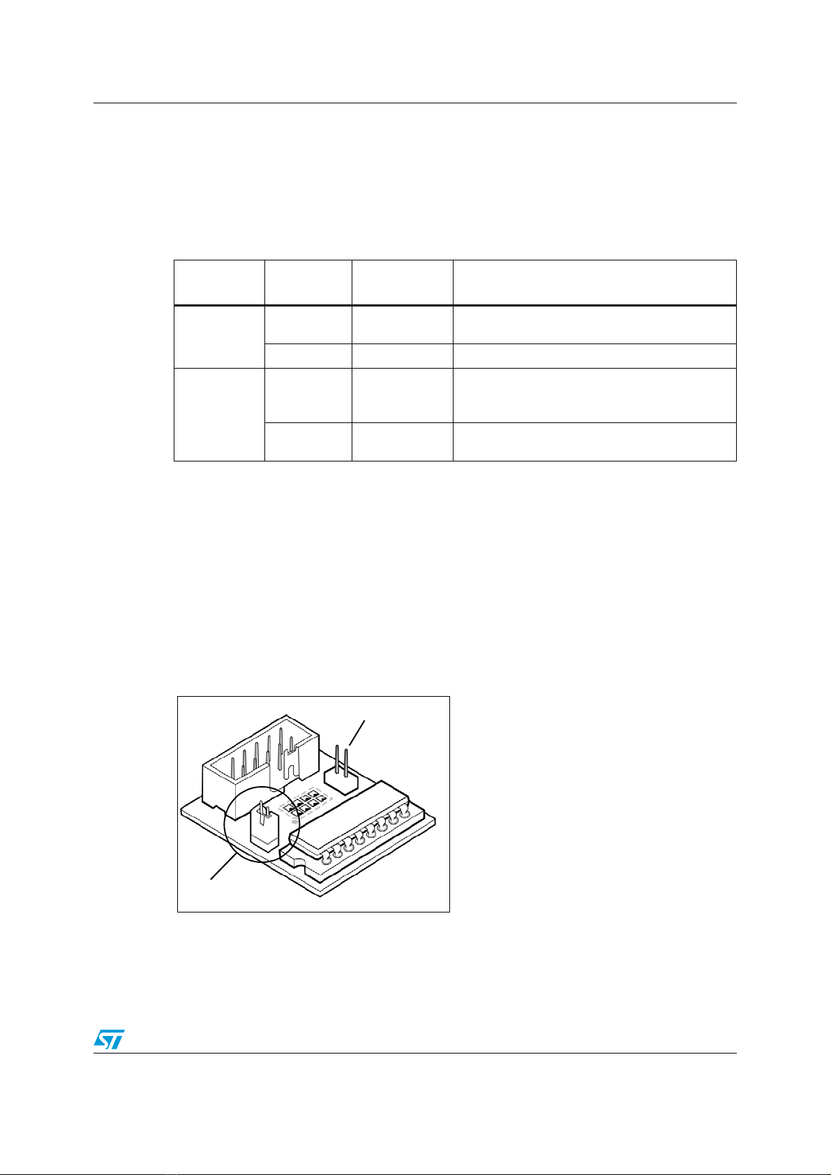
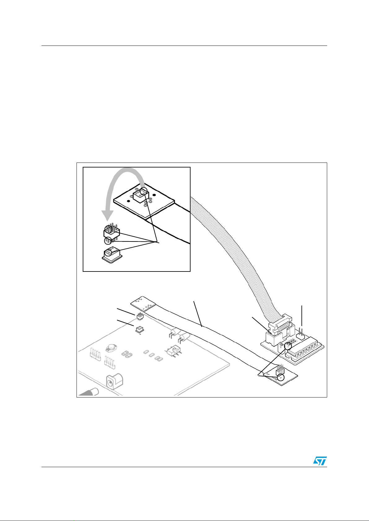
Figure 3. ICD On jumper (TP1)
To set the ICD On jumper (TP1):
1. Make sure the in-circuit debugging tool
and the application are powered off.
2. Place the jumper on TP1 as shown in
Figure 3
.
3. Connect to and power on the in-circuit
debugging tool and application board.
Refer to the on-line help of your integrated
development environment/debugging
software for further information about in-
circuit programming and debugging the
microcontroller on the ICD adapter.
TP1 fitted for ICD
TP2 not fitted
for ICD
MB509