Stack ST8302 User manual

Part No./Issue No. ST542075-001
ST8302 and ST8360 Video-Logger
System
Users Guide


STACK ST8302 and ST8360 Video-Logger System Preface
User Guide i
Preface
Thank you!
Thank you for purchasing the Stack Video-Logger system. Whether you
have opted for the Standalone ST8302 or the Expansion ST8360 package,
it will give you a wealth of information that will help you get the
maximum safe performance from your vehicle.
Registration Form
Please complete and return the registration form contained in the
package. This will allow us to keep you up to date on the latest
developments from Stack.
This manual
This manual will help you install and use the Stack ST8302 and ST8360
Video-Logger systems. It explains how to set up and configure each
system for your vehicle.
Edition Notice
This edition is for all versions of the ST8302 and ST8360 Video-Logger
systems distributed to customers world wide. The units of measurement
used to illustrate the use of the system in this edition are for the UK
version. Units used in the other versions are shown in the following
table.
Parameter Type UK Version US Version EC Version
Speed MPH MPH km/h
Temperature Degrees C Degrees F Degrees C
Wheel Circumference Millimetres Inches Millimetres
Pressure PSI PSI Bar
Distance Metres Feet Metres

Preface STACK ST8302 and ST8360 Video-Logger System
ii User Guide
Getting Help
Stack and its approved distributors provide a comprehensive Technical
Help service to assist with your enquiries. Contact your local Stack branch
or distributor. A current list of distributors can be found on the Stack
websites at www.stackltd.com or www.stackinc.com
Related Products from Stack Limited
If you need information about other Stack motor sport products, these can
be obtained from Stack or from your local Stack dealer. Products available
from Stack include:
•Intelligent Tachometers
•Action Replay Tachometers
•Performance Analysers
•Speedometers
•Boost Gauges
•Analog Sensors
•Digital Sensors
•Data Logging Systems
•Display and Logging
Systems
•Radio Telemetry Systems
•Display and Analysis
Software
Stack is a registered trademark of Stack Limited.
Information in this publication is subject to change without notice and does not represent a
commitment on the part of Stack Limited. No responsibility is accepted for error or
omission.
Copyright 2004 Stack Limited
United Kingdom Telephone Numbers:
Sales: 01 869 240404
Tech Support: 01 869 240420
Fax: 01 869 245500
Web site: www.stackltd.com
United States Telephone Numbers:
Sales: 888-867-5183
Fax: 888-364-2609
Web site: www.stackinc.com

STACK ST8302 and ST8360 Video-Logger System Contents
User Guide iii
Table of Contents
Chapter 1. Introduction 1
Product Versions 2
How to use this manual 5
Chapter 2. Getting Started 6
Initial Checks 6
Optional Items 6
The Video Camera and Video Recorder 7
Putting the System Together 11
The Power Supply 14
The Display 14
The Video Controller 19
Switching the Camera On and Off 20
Starting and Stopping Recording 20
Peak Values 21
Update of Peak Values 22
Alarms 25
Lap 27
Gears 27
Chapter 3. Configuration 28
Entering Configuration Mode 28
Navigating the Configuration Menu 29
Configuration Menu Items 29
Restoring Default Values 43
Chapter 4. Installation 44
The V/VS Module 45
Attaching the Harnesses 46
Engine Speed (RPM) Measurement 49
Wheel Speed Sensor 51
Oil and Fuel Pressure Sensors 53
Temperature Sensors 54
Lap Timing Sensor 55
Brake Pressure Sensor/Switch 57
Throttle Angle Sensor 58
Battery Connection 59

Contents STACK ST8302 and ST8360 Video-Logger System
iv User Guide
Chapter 5. Troubleshooting 60
Appendix A – Video Harness Wiring Diagram 70
Appendix B – Sensor Harness Wiring Diagram 71
Appendix C – Throttle/Brake Harness Wiring Diagram 72
Appendix D – Returned Goods Form 73
Index 74

STACK ST8302 and ST8360 Video-Logger System Chapter 1. Introduction
User Guide 1
Chapter 1. Introduction
The Stack VCR Video-Logger system transforms your in-car video recorder
into a powerful data-logging system without the need for a PC. Using video
overlay technology, real-time performance data is superimposed onto the
video picture along with engine parameters and driver activity channels.
The Video-Logger System can:
•Be used with most race PAL or NTSC video systems
•Connect to dedicated sensors and an existing Stack display, steering
wheel or logging device
•Start and stop video recording automatically based on RPM
•Display peak values for all parameters at the end of recording
•Display user-configured alarm messages for engine temperatures
and pressures on the video screen, with rapid navigation between
alarms

Chapter 1. Introduction STACK ST8302 and ST8360 Video-Logger System
2 User Guide
Product Versions
Standalone Video-Logger System
The Standalone Video-Logger comprises a sensor and harness for use
with an existing race video system.
ST8302VS VCR Video-Logger
ST8302VSM VCR Video-Logger ‘Max’
Expansion Video-Logger System
For vehicles with a STACK ST8100/ST8102 display and existing race
video system.
ST8360V Video-Logger Expansion
ST8360VM Video-Logger Expansion ‘Max’

STACK ST8302 and ST8360 Video-Logger System Chapter 1. Introduction
User Guide 3
Standalone system (ST8302VS and ST8302VSM ‘Max’)
The Video-Logger system connects between the remote-mounted video
camera and the video recorder.
The video recorder must have an A/V-in connecter (4W 3.5mm Jack socket)
for use with a CCTV-type remote camera.
Many of the Stack Video-Logger’s ease-of-use features rely upon the
recorder having a ‘LAN-C’ control connector (3W 2.5mm Jack socket).
Although the LAN-C connection is not essential for operation, it is highly
recommended and ensures that the best possible video quality and
reliability is achieved (see p.7-8).
External sensor inputs:
Internal channels:
•Distance
•Lateral-G and longitudinal-G
•Min/Max corner/straight speed
•Gear
•Predictive lap timer
•Alarm count
•Battery Voltage
•RPM
•Speed
•Oil temperature
•Water temperature
•Brake pressure or
brake switch
•Oil pressure
•Fuel pressure
•Throttle angle
•Lap times

Chapter 1. Introduction STACK ST8302 and ST8360 Video-Logger System
4 User Guide
Expansion system (ST8360VS and ST8360VSM ‘Max’)
The Expansion system connects to the harness of an existing Stack
display, steering wheel or logging device.
The harness provides power for the system and access to data from the
existing sensors. This saves duplicating sensors and makes for a
simpler installation overall.
Inputs from Stack display system:
•RPM
•Speed
•Oil temperature
•Water temperature
•Oil pressure
•Fuel pressure
•Battery volts
•Lap times
External sensor inputs (require additional harness):
•Throttle angle •Brake pressure (option) or
brake switch
Internal channels:
•Distance
•Lateral-G and longitudinal-
G
•Min/Max corner/straight
speed
•Gear
•Predictive lap timer
•Alarm count
•Battery Voltage

STACK ST8302 and ST8360 Video-Logger System Chapter 1. Introduction
User Guide 5
How to use this manual
Stack recommends that you unpack and connect the components in the
system before you install it in your vehicle. This will enable you to
familiarise yourself with operating the display and configuring it for
the vehicle in which you intend to install it.
In Chapter 2 – Getting Started, we’ll show you how to do this. By the
end of Chapter 2, you will have set up the system, proved that it is
functioning correctly and become familiar with its operation.
In Chapter 3 – Configuration, we’ll show you how to configure the
system for your own particular vehicle.
In Chapter 4 – Installation, we’ll talk you through the process of
installing the configured system ‘for real’ in your vehicle.
Finally, in Chapter 5 – Troubleshooting, we’ll look at any problems you
might have when using your equipment and suggest ways of resolving
them.
The Appendices provide supplementary information that may prove
useful.
Please note: This manual does not attempt to explain how to
interpret or use the data from the Video-Logger system, as this will be
specific to the type of vehicle in which it is installed and the type of
competition in which it is engaged.

Chapter 2. Getting Started STACK ST8302 and ST8360 Video-Logger System
6 User Guide
Chapter 2. Getting Started
This chapter guides you through the initial unpacking and setting up of
the equipment for pre-installation checks and familiarisation with its
operation.
Initial Checks
Check that you have the right components for your system before
attempting to put it together. Please refer to the packing list that was
included in your product shipment.
Optional Items
Optional Items for ST8302 Standalone System
The ST8302VS and ST8302VSM Video-Logger systems can be used
with the following optional components:
Quantity Description
2 ST747 10 Bar / 150 PSI Pressure Sensor
2 ST991 -20°C - 150°C Fluid Temperature Sensor
1 ST970 / ST979 / ST483 Throttle Sensor
1 ST749 Brake Pressure Sensor
Optional items for ST8360 Expansion System
The ST8360V and ST8360VM Video-Logger systems can be used with
the following optional components:
Quantity Description
1 ST546 Infrared Lap-Timing System
1 ST5097 Manual Lap Timer
1 ST549 Brake Pressure Sensor
1 ST970 / ST979 / ST483 Throttle Sensor
1 ST892V Brake/Throttle Harness

STACK ST8302 and ST8360 Video-Logger System Chapter 2. Getting Started
User Guide 7
The Video Camera and Video Recorder
These are not supplied with the system, so you should provide your own
suitable equipment.
Although most ‘camcorders’ consist of both camera and recorder in one
unit, you must use a separate camera, often called a ‘lipstick’ or ‘bullet’
camera, to obtain the image.
Your video recorder must:
•Be either NTSC or PAL format (you needed to specify which when
you purchased your Video-Logger system, because each format
requires a different V/VS Module). Typically, NTSC format is used
in the USA and PAL in Europe.
•Have an A/V input to connect an external camera.
•Have a display screen which is clear and not too small, so that the
configuration menus are readable. The camera’s viewfinder could
be used in exceptional circumstances.
•Ideally have a LAN-C port, which is required for automatic
operation.
To facilitate fully-automatic operation, your camera should have a
LAN-C port. This allows the system to start and stop recording when
the engine speed reaches a specified RPM
With a LAN-C port the camcorder can be put into ‘standby’ mode, to
preserve battery life. In addition, the LAN-C port is required to report
the true recording status of the camera.

Chapter 2. Getting Started STACK ST8302 and ST8360 Video-Logger System
8 User Guide
The following table shows the recommended operational differences
between LAN-C and non LAN-C recorders:
V
VS
LAN-C Non-LAN-C
RECORD switch = Toggle log +
Reset Peaks, Laps and PLT
RECORD switch = Reset Peaks,
Laps and PLT (if Memory Card
or Tape is full)
RECORD switch = Reset Peaks, Laps and
PLT
Must turn off “Start RPM” test to prevent a
reset every time the Engine Speed goes
through 3000rpm
Must use Display System (ST8100) switches to Reset Peaks, Laps and PLT
Turn on “Peaks MPH” test only if the vehicle has its ignition off on the grid. This
will prevent peak values being shown as the race starts
Recorder automatically stops
recording when V/VS module is
switched off
Recorder may or may not stop recording
when V/VS module is switched off
Relies on Engine Speed
exceeding the “Start RPM” test
value to start recording
Recorder must be started manually
PLT = Predictive Lap Timer (“Max” systems only)
Table 1 – LAN-C and non LAN-C Video Recorders

STACK ST8302 and ST8360 Video-Logger System Chapter 2. Getting Started
User Guide 9
The Sensor Wiring Harness
The sensor wiring harness carries data from the sensors to the VS
Module. Each of the wires in the harness is labelled to show which
sensor it should be connected to. See Appendix B for a full diagram of
this harness.
Labels Connects To
WS Wheel speed sensor
LAP Lap timing sensor
SL Gear shift warning light
AL Alarm warning light
ES Engine speed (rpm)
OT Oil temperature sensor
WT Water temperature sensor
OP Oil pressure sensor
FP Fuel pressure sensor
BP Brake pressure sensor or switch
TP Throttle position sensor
B + Battery positive
B - Battery negative (earth)
Table 2– Sensor wiring harness

Chapter 2. Getting Started STACK ST8302 and ST8360 Video-Logger System
10 User Guide
The Video Wiring Harness
The video wiring harness connects the VS (ST8360) or V (ST8302) module to
the video system and is identical for both the Standalone and Expansion
systems.
Connect the video harness as shown in Table 3.
Labels Connects to
AV Audio/video input of recorder
L Left (L) microphone line input level
R Right (R) amplified microphone
CAM External camera
12V 2 x 12v power supply (for camera, microphone, etc)
LANC Lan-C connector on recorder
VC Video controller
Table 3 – Video harness connections

STACK ST8302 and ST8360 Video-Logger System Chapter 2. Getting Started
User Guide 11
Putting the System Together
The ST8302 Standalone System
VIDEO CONTROLLER
ON/OFF
PEAK
RECORD
NEXT
RESET
DEC INC
MENU
ST8302 Standalone System
Microphone(s)
Camera Video in Video out
Video Controller
Remote Control (LAN-C)
"VS" Module
Video and Sensor Interface
On-board Video Recorde
r
RPM
Water Temperature
Oil Temperature Car Battery
Shift Lamp Alarm Lamp
Oil Pressure
Fuel Pressure
Lap Timing System
Throttle Angle
Speed
= Race Video System (Not Supplied)
Brake Pressure or Switch
Diagram 1 – The ST8302 Standalone system
The Standalone system comprises:
•The VS module video and sensor interface
•Various sensors (including those provided with the system and
others purchased separately)
•A sensor wiring harness with a 19-way connector, providing the VS
module with data from the sensors
•A video camera, microphone and recorder set-up (not included
as part of the system)
•A video wiring harness with a 15-way connector, which carries
video, sound and the data from the VS module for overlay onto the
video display

Chapter 2. Getting Started STACK ST8302 and ST8360 Video-Logger System
12 User Guide
Connecting the ST8302 Standalone System
1. Connect each of the sensors to the appropriate cable in the sensor
wiring harness, as shown in Table 1 above.
2. Connect a 12v DC power supply to the power input cable.
3. Connect the VS Module to the video system using the video harness, as
described in Table 3 above.
If you do not have the correct connectors for your video recorder,
camera or microphones, adapters can be purchased from your local
electrical supplier.
Components of the ST8360 Expansion system
The Expansion system comprises:
•The V module video interface
•A Stack Display device (such as the ST8100 Display system shown
in the diagram) receiving input from various sensors attached to it by
a wiring harness
•A CANBus cable with a 4-way connector which connects the V
module to the existing harness on the Stack Display device
•A video camera, microphone and recorder set-up (not included
as part of the system)
•A video wiring harness with a 15-way connector, which carries the
data from the V module for overlay onto the video display (see Table
3)

STACK ST8302 and ST8360 Video-Logger System Chapter 2. Getting Started
User Guide 13
VIDEO CONTROLLER
ON/OFF
PEAK
RECORD
NEXT
RESET
DEC INC
MENU
WATER 78 OIL T 98
SPEED 123 OIL P 47
ST8100 Display System
Microphone(s)
Camera Video in Video out
Stack CANBus Network
Video Controller
Optional
Brake Pressure Sensor or Switch
Remote Control (LAN-C)
"V" Module
Video Interface
On-board Video Recorde
r
RPM
Water Temperature
Oil Temperature
Oil Pressure
Fuel Pressure
Lap Timing System
Speed
= Race Video System (Not Supplied)
Diagram 2 – The ST8360 Expansion system
Connecting the ST8360 Expansion System
1. Connect the V module to the Stack device with the CANBus cable
2. Connect a 12v DC power supply to the Stack device
3. Connect the V Module to the video system using the video harness,
as described in Table 3 above.

Chapter 2. Getting Started STACK ST8302 and ST8360 Video-Logger System
14 User Guide
The Power Supply
We suggest that you set up the system outside of the vehicle initially, to
familiarise yourself with its use. You will need to connect a 12v DC
power supply. Once the system has been installed in a vehicle, then the
vehicle’s own battery will supply the power.
The Display
The Stack Video-Logger system overlays data on the video image
received by your camera. This data comes either directly from the
sensors (in the Standalone ST8302 system), or from another Stack device
(in the Expansion ST8360 system).
Diagram 3 – The Stack Video-Logger display
This manual suits for next models
1
Table of contents
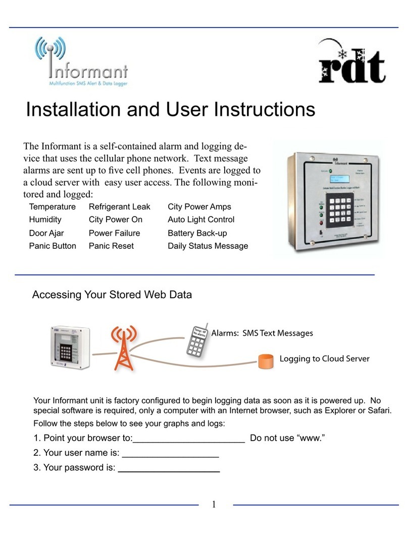
Popular Security System manuals by other brands

Alarm Lock
Alarm Lock Trilogy DL4100 Series Addendum Programming instructions
Gardsman
Gardsman CTC-1131 Installation, programming, operating
NexSens
NexSens G2-RAIN quick start guide
Ritron
Ritron RGG1 quick start guide
Amico
Amico Alert-3 LCD v2.3 Retro-Fit Manual
Whelen Engineering Company
Whelen Engineering Company 6220-01-057-0746 installation guide
