Staco Energy FirstLine P User manual

003-2551 REV B
FirstLine P
FirstLine P 924
BATTERY CABINET
USER MANUAL

i | Page
No reproduction of any part of this manual, even partial, is permitted without the authorization of Staco
Energy Products Company. The Staco Energy Products Company reserves the right to modify the
product described herein, in order to improve it, at any time and without notice.
301 Gaddis Boulevard • Dayton, Ohio 45403
U.S. Toll Free 866-261-1191
(937) 253-1191 • Fax: (937) 253-1723
Web site: www.stacoenergy.com
Thank you for choosing our product.

ii | Page
Safety Warnings
IMPORTANT SAFETY INSTRUCTIONS
SAVE THESE INSTRUCTIONS
This manual contains important instructions for FirstLine P Battery Cabinets that should be followed
during installation and maintenance of the battery cabinet. Please read all instructions before operating
the BATTERY CABINET and save this manual for future reference.
READ AND FOLLOW ALL SAFETY INSTRUCTIONS
a. Do not use outdoors.
b. Do not route wiring across or near hot surfaces.
c. Do not install near gas or electric heaters.
d. Use caution when servicing batteries. Battery acid can cause burns to skin and eyes. If acid is
spilled on skin or in eyes, flush acid with fresh water and contact a physician immediately.
e. Unit should be installed where it will not readily be subjected to tampering by unauthorized
personnel.
f. The use of accessory equipment not recommended by the manufacturer may cause an unsafe
condition.
g. Do not use this battery cabinet for other than intended use.
This battery cabinet has been designed and manufactured in accordance with the standards for
the product, for normal use and for all uses that may reasonably be expected. It may under no
circumstances be used for any purposes other than those envisaged, or in any other ways than
those described in this manual. Any interventions should be carried out in accordance with the
criteria and the time-frames described in this manual.
WARNING
A battery can present a risk of electrical shock and high short circuit current. The following
precautions should be observed when working on batteries:
1) Remove watches, rings, or other metal objects.
2) Use tools with insulated handles.
3) Wear rubber gloves and boots.
4) Do not lay tools or metal parts on top of batteries.
5) Disconnect charging source prior to connecting or disconnecting battery terminals.
6) Determine if the battery is inadvertently grounded. If inadvertently grounded, remove
source of ground. Contact with any part of a grounded battery can result in electrical
shock. The likelihood of such shock will be reduced if such grounds are removed during
installation and maintenance
Staco Energy is highly specialized in the development and production of battery cabinets. The
battery cabinets of this series are high quality products, carefully designed and manufactured to
ensure optimum performance.

iii | Page
This Battery Cabinet contains LETHAL VOLTAGES. All repairs and service should be
performed by AUTHORIZED SERVICE PERSONNEL ONLY. There are NO USER
SERVICEABLE PARTS inside the Battery Cabinet.
To reduce the risk of fire or electric shock, install This Battery Cabinet in a temperature and
humidity controlled, indoor environment, free of conductive contaminants. Do not operate
near water or excessive humidity (95% maximum).
WARNING
This Battery Cabinet contains its own energy source (batteries). Hazardous voltage may be
present even when the battery cabinet is not connected to a power source
Batteries can present a risk of electrical shock or burn from high short circuit current.
Observe proper precautions. Servicing should be performed by qualified service personnel
knowledgeable of batteries and required precautions. Keep unauthorized personnel away
from batteries.
There is a risk of explosion if batteries are replaced by an incorrect type. Replace with same
type and rating only. See Table 10
Proper disposal of batteries is required. Refer to your local codes for disposal requirements.
Never dispose of batteries in a fire
WARNING
This product contains Valve Regulated Sealed Acid Batteries.
These batteries contain lead, a neurotoxin, and sulfuric acid, a corrosive. Additionally, the
energy stored in the batteries can present a shock hazard and a burn hazard. Batteries
should only be serviced by trained personnel. Appropriate safety precautions must be
observed, including eye protection and skin protection. Contact with electrolyte requires
flushing with a generous amount of clean water. Seek medical attention immediately
following contact with electrolyte. Unwanted batteries must be recycled and should never be
discarded.
WARNING
Do not dispose of battery or batteries in a fire. The battery may explode.
Do not open or mutilate the battery or batteries. Released electrolyte is harmful to the skin
and eyes. It may be toxic.
DANGER
WARNING
iv | Page
Emergency Interventions
The following information is of a general nature.
First aid interventions
Company regulations and traditional procedures should be followed for any first aid intervention that may
be required.
Firefighting measures
1. Do not use water to put out a fire, but only fire extinguishers that are suitable for use with
electrical and electronic equipment.
2. If exposed to heat or fire, some products may release toxic fumes into the atmosphere. Always
use a respirator when extinguishing a fire.
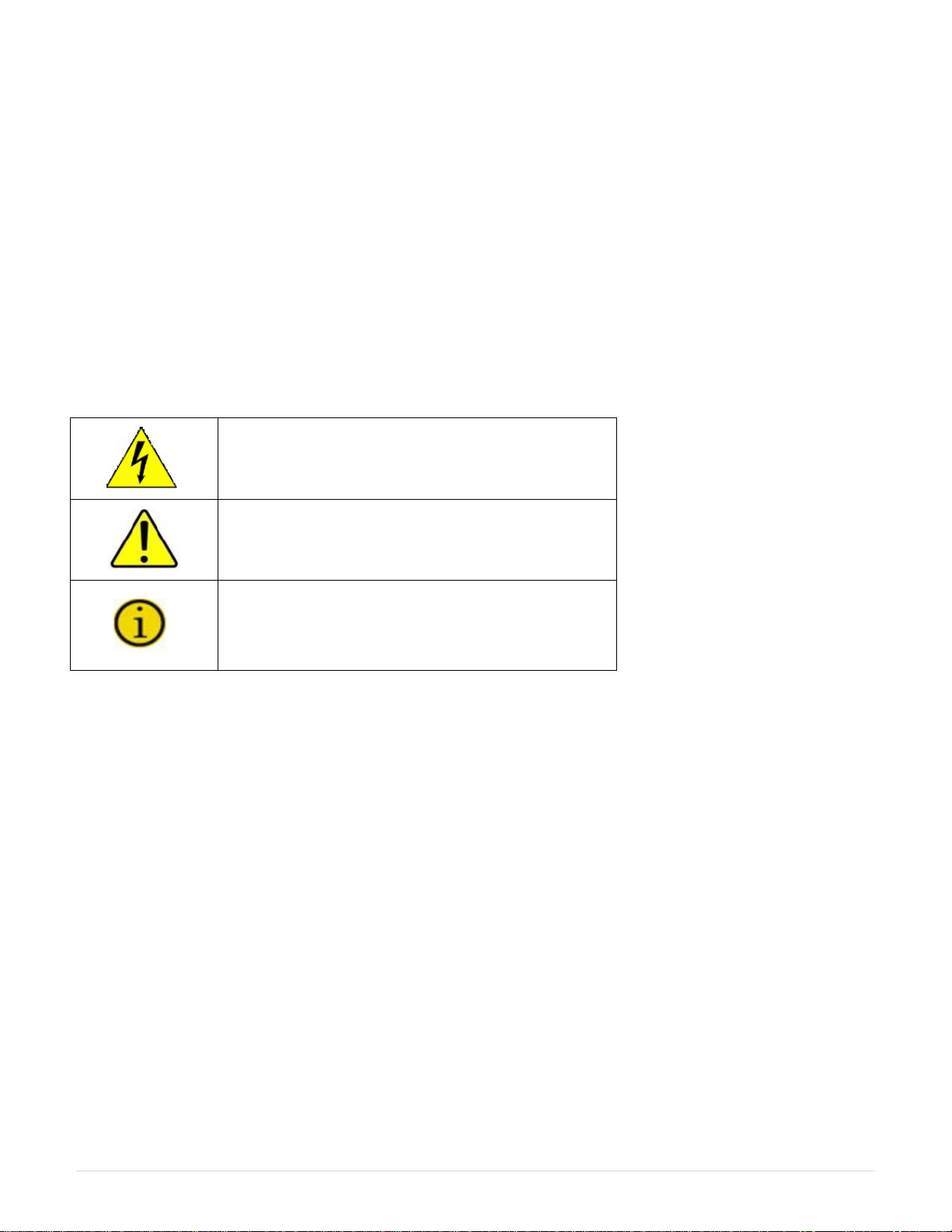
Symbols used in the Manual
In this manual, some operations are shown by graphic symbols to alert the reader to the dangerous
nature of the operations:
Danger / Risk of Electric Shock
This symbol indicates possibility of serious injury
or substantial damage to the unit, unless
adequate precautions are taken.
Warning
This symbol indicates important information which
must be understood and any stated precautions
taken
Note
Protective Equipment
No maintenance operations shall be carried out on the unit without wearing the Personal Protective
Equipment (PPE). Personnel involved in the installation or maintenance of the unit must be properly
clothed.
General Precautions
This manual contains detailed instructions for the use, installation and start-up of the Battery Cabinet.
Read the manual carefully before installation. For information on using the Battery Cabinet, the manual
should be kept close at hand and consulted before carrying out any operation on the Battery Cabinet.

v | Page
Table of Contents
Safety Warnings..................................................................................................................................... ii
Emergency Interventions ..................................................................................................................... iv
First aid interventions ...........................................................................................................................iv
Firefighting measures...........................................................................................................................iv
Symbols used in the Manual................................................................................................................ iv
Protective Equipment........................................................................................................................... iv
General Precautions............................................................................................................................. iv
1 Battery Cabinet Setup......................................................................................................................... 1
1.1 Storage...........................................................................................................................................1
1.2 Inspecting the Equipment...............................................................................................................1
1.3 Floor Loading ................................................................................................................................. 2
1.4 Clearances..................................................................................................................................... 2
1.5 Dimensions..................................................................................................................................... 2
2 Installation...........................................................................................................................................3
2.1 Unpacking ......................................................................................................................................3
2.2 Electrical Installation.......................................................................................................................4
2.2.1 Wiring Preparation...................................................................................................................5
2.2.2 Connecting To the Firstline Battery Cabinet............................................................................. 5
2.3 Circuit Breaker Interface.................................................................................................................6
3 Operation............................................................................................................................................. 9
4 UL924 Emergency Lighting Systems ................................................................................................ 9
5 Battery Removal, Installation, and Service..................................................................................... 10
6 Maintenance...................................................................................................................................... 11
7 Specifications.................................................................................................................................... 13
Figures
Figure 1 – Battery Storage Duration........................................................................................................1
Figure 2 – FirstLine P Battery Cabinet Layout......................................................................................... 2
Figure 3 - Pallet Mounting Hardware....................................................................................................... 3
Figure 4 – Electrical Connections............................................................................................................ 4
Figure 5 - Circuit Breaker Interface Board Assembly Location................................................................. 7
Figure 6 - Circuit Breaker Interface Board Assembly............................................................................... 7
Figure 7 - UPS REPO Connections......................................................................................................... 7
Figure 8 - Battery Cabinet to the UPS Remote Emergency Power Off (REPO) Switch Interface............. 8
Figure 9- Battery Layout....................................................................................................................... 10
Figure 10 - Cabinets Schematic............................................................................................................ 12
Tables
Table 1 – Battery Models approved for UL924......................................................................................... 9
Table 2 – UL924 Approved Systems ....................................................................................................... 9
Table 3 – Battery Replacement Quantities............................................................................................. 11
Table 4 – Recommended Replacement Intervals .................................................................................. 11
Table 5 – Factory Breaker & Fuse settings............................................................................................ 13
Table 6 - Input / Output Cable Size and Torques................................................................................... 13
Table 7 - Ground Cable Size and Torques ............................................................................................ 13
Table 8 - Circuit Breaker Interface Board Cable Size and Torques........................................................ 13
Table 9 - Model Floor Loadings............................................................................................................. 13
Table 10 – Battery Models..................................................................................................................... 13

1 | Page
1 Battery Cabinet Setup
1.1 Storage
The batteries in your Staco system were shipped from the factory fully charged. If you plan to place the
batteries in storage for any period of time prior to installation and startup then the following precaution
should be followed.
Batteries placed in storage will age. How fast they will age depends on the storage temperature. The
batteries are rated for storage over a temperature range of -15o C to 40o C (5o F to 104o F). The amount
of time the batteries may be stored without recharge varies greatly with storage temperature. Please
consult the following Figure 1. If the batteries are allowed to sit in storage for an excessive period of
time before recharging then they are subject to irreversible damage.
Figure 1– Battery Storage Duration
Once the batteries are placed into service and fully charged, the useful life of the batteries will be
reduced if they are subjected to high temperatures. The operating temperature range of -15o C to 40o C
(5o F to 104o F) must not be exceeded for even short periods of time. Batteries operating continuously at
or near 40o C will experience a shorter useful life than batteries operating continuously at 25o C. Battery
life will be further shortened if the batteries are allowed to fully discharge and then left in that condition for
extended periods of time. As soon as the load is removed from the battery it will continue to age at a
higher rate than a fully charged battery. The longer the battery remains discharged the greater the risk of
irreversible damage.
Allowing the batteries to become damaged due to; a) operation or storage outside the rated
temperature range, b) storage for extended periods of time without recharge per the Figure 1
above, or c) sitting for a period of time in a discharged state will void the battery warranty.
1.2 Inspecting the Equipment
If any equipment has been damaged during shipment, keep the shipping and packing materials for the
carrier or place of purchase and file a claim for shipping damage. If you discover damage after
acceptance, file a claim for concealed damage.
To file a claim for shipping damage or concealed damage: 1) File with the carrier within 15 days of
receipt of the equipment, 2) Send a copy of the damage claim within 15 days to your service
representative.
2 | Page
1.3 Floor Loading
When planning the installation, consider the battery cabinet weight for floor loading. The strength of the
installation surface must be adequate for point and distributed loading. The approximate weights are
shown in Table 9.
1.4 Clearances
The following clearances are recommended for the FirstLine P Battery Cabinet.
From Front of Cabinet
36” (91.4 cm) working space
From Back of Cabinet
0” (0 cm)
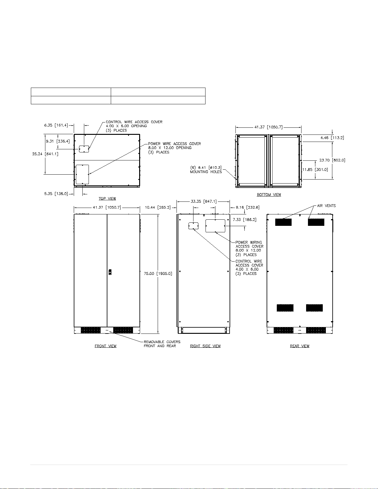
1.5 Dimensions
Figure 2– FirstLine P Battery Cabinet Layout

3 | Page
2 Installation
2.1 Unpacking
The following tools are required for unloading the cabinet(s):
Wrenches for 3/8” lag bolts.
Forklift or pallet jack
Phillips screwdriver
WARNING
The Battery Cabinets are heavy (see Table 9). Unloading the cabinets requires at least two
people to safely remove the cabinets from the pallet.
To remove the battery cabinet from the ship pallet:
1. Make sure the forklift is rated for the cabinet weight.
2. Make sure the path traveled has sufficient support for the combined weight of the forklift and the
battery cabinet.
3. Make sure forks are at maximum separation.
4. Use a very strong ratchet strap (or similar device) of sufficient strength to tie the upper part of the
cabinet to the forklift tower before moving.
5. Keep people out of the fall zone. If the cabinet topples over, stand clear.
6. With a Phillip’s screwdriver, remove the four kick panels. These will be remounted when the
cabinet is in place.
7. Remove all banding, wrapping and foam protection.
8. Remove the six 3/8” lag bolts securing the cabinet to the pallet. (See Figure 3)
Figure 3- Pallet Mounting Hardware
9. Lift the cabinet with a forklift one to two inches (1”-2” [2.5-5cm]) above the pallet.
10. Slide the pallet completely away from the raised cabinet.
11. Carefully move the cabinet to the desired location and slowly lower the cabinet to the floor or
other appropriate flat surface.
12. Remount the four kick panels

4 | Page
2.2 Electrical Installation
The FirstLine P Battery Cabinet has the following power connections:
2-pole (positive, negative) terminal block and ground connection for battery power input and output.
Each pole has compression lug holes. One connection goes to the UPS or to the next Battery Cabinet
closer to the UPS. The second connection goes to the input of the next Battery Cabinet, if supplied.
In order to completely isolate the battery cabinet for maintenance, a DC disconnect switch or DC breaker
should be installed between the battery cabinet and UPS.
Figure 4– Electrical Connections
WARNING
Only qualified service personnel (such as a licensed electrician) should perform the UPS
installation and initial startup. Risk of electrical shock.
WARNING
!
USE COPPER
CONDUCTORS ONLY
CAUTION!
FORUSE IN A CONTROLLED ENVIRONMENT.REFER
TOHA NDBOOK F OR ENVIRONMENTAL
CONDITIONS.
ATTENTION:
Pouruti lisation en atmosphèrecontrolée.
Consulte r la noti ce te chnique pour les
conditions dumilieu.
DO NOT DISCONNECT
UNDER LOAD
Donot clos e the circuit breakeruntil
the displ ay of the UP S nolonger shows:
Wait: DO NOT connect the BATTERY
Closingth e breaker before t his may damage the
UPSor blow fuses in the bat tery cabinet.
WARNING!
BATTERY
CIRCUIT BREAKER

5 | Page
2.2.1 Wiring Preparation
To begin wiring the UPS:
1. Verify that the electrical connections to the installation site have been properly installed.
2. Wire the FirstLine UPS per the User’s Manual.
3. Switch off utility power to the distribution point where the UPS is connected. Be absolutely sure there
is no power.
4. Open the front door of the Battery Cabinet
5. Switch the circuit breaker to the “Off” position.
6. Remove the terminal access cover on the breaker on the right (load side) (see Figure 4).
7. Conduit landing plates are located toward the on the top cover, side panels, and base to
accommodate bottom wire entry to the cabinet (see Figure 2). Remove plates and drill or punch
hole to fit conduit bushing with Greenlee punch or similar device. Make certain that the bushing will
be clear in the opening in the base. Mount bushing to plate and tighten to manufacturer’s
recommendations.
8. Replace the plates and mount conduit.
2.2.2 Connecting To the Firstline Battery Cabinet
1. Check that the circuit breakers are in the “Off” or open position.
2. Inspect battery trays for signs of damage. Verify that all terminal connections are sound.
3. With wire sized per the Table 6, connect one wire to the terminal block pole marked positive (+)
and one wire to the terminal block pole marked negative (-).
4. Connect the ground wire to the 1/4-20 ground stud with a ring terminal or pressure lug by
removing and replacing the top nut and washers.
5. Before working within the UPS cabinet, verify that the UPS has no power applied. Refer to the
UPS manual. Repeat procedures 3 and 4 to the FirstLine P UPS Battery connector located in the
right side of the UPS. We recommend that the wires be marked as to which is positive (+) and
negative (-) to ensure that the wires are not accidentally crossed.
6. If a second battery cabinet is present, repeat the procedure to install wires connecting the
terminals on the second cabinet to the unused terminals (of each pole of the terminal block) on
the first cabinet.
7. If additional cabinets are present, continue this process until all cabinets are connected.
DANGER
Never connect the positive to the negative. Severe damage and injury could result.
8. Connect the Circuit Breaker Interface per Section 5 if it is desired to implement the remote
emergency power off function.
9. Close front doors to cabinet.

6 | Page
2.3 Circuit Breaker Interface
Figure 5shows the location of the circuit breaker interface terminal blocks in the Battery Cabinet.
The circuit breaker interface must be connected to the UPS if it is desired to have the Battery Cabinet
circuit breaker trip when the Remote Emergency Power Off (REPO) signal is applied to the UPS.
Additional Battery Cabinets must connect to the pass-through connection provided for this function (see
Figure 8).
If it is not desired to have the Battery Cabinet Breaker trip on REPO activation, then these connections
can be omitted.
This function requires 3 wires between the battery cabinet and the UPS. The wires can be part of a
jacketed cable assembly or they can be three individual wires. Local codes may require that the wires be
run in a conduit. In any case, these low voltage signal wires must be kept physically separated from the
power wiring between the Battery Cabinet and the UPS.
Refer to the section in the UPS manual "REMOTE COMMANDS, ALARMS AND EPO" for the location of
the Terminal Block in the UPS where the Battery Cabinet signals are to be connected. The UPS is
factory-fitted with a shorting jumper between terminals 13 and 14. This jumper must be removed for the
REPO function to be enabled (See Figure 7).
The terminal blocks TB1 and TB2 are pluggable connectors for ease of wiring. Carefully pull each
terminal block loose from the circuit breaker interface board to wire as instructed below and plug them
back into place. A small flat screwdriver is required to tighten each wire in place; tighten as specified in
Table 8.
From TB1 in the Battery Cabinet, connect a wire from terminal 1 to terminal 10 in the UPS. Connect a
second wire from TB1 terminal 2 to terminal 13 in the UPS. Connect a third wire from TB1 terminal 3 to
terminal 14 in the UPS.
If a second Battery Cabinet is to be connected in parallel with the first, three control wires need to
connect TB1 in the second cabinet to TB2 in the first, terminal 1 to terminal 1, terminal 2 to terminal 2,
terminal 3 to terminal 3. If additional cabinets are present, this same procedure applies.
Finally, the UPS will not operate unless a normally closed REPO switch is connected across terminals 13
and 14 at the UPS. Refer to the wiring diagram, Figure 8. Note that terminals 2 and 3 in the battery
cabinet are wired in parallel with terminals 13 and 14 of the UPS. If desired, the REPO switch can be
connected to terminals 2 and 3 of TB2 instead of 13 and 14 of the UPS.
Usually, this normally closed contact is part of a push-button switch. If multiple switches are desired, the
multiple normally closed contacts must be wired in series such that the operation of any switch causes
the connection across the REPO terminals to be opened. Wiring of this switch circuit should be run in
metal or metal shielded conduit for maximum protection. Damage to or interference with this circuit can
cause the UPS to trip off.
During commissioning of the UPS installation, the REPO system should be tested. Start the UPS. When
the UPS display no longer states "Wait: DO NOT connect the BATTERY", close the breaker on each of
the battery cabinets. Operate the REPO switch and verify that the UPS shuts down and that all of the
battery cabinet breakers trip.
NOTE: Wires to the circuit breaker interface board must not enter the UPS or Battery Cabinet
through the same port as the input/output or battery power wires. Wires to the battery cabinet
must enter through the removable cover over the circuit breaker interface board.

7 | Page
Figure 5- Circuit Breaker Interface Board Assembly Location
Figure 6- Circuit Breaker Interface Board Assembly
Figure 7- UPS REPO Connections
U1 TB3
TB2
TB1
R7
R6
R5
R4
R1 R2
Q2
Q1
Q3
D4
D3
D2
C8
C3 C6
C5
C4
C2
C1
SENSITIVE DEVICE
ELECTROSTATIC
ATTENTION
1 2 3
1 2
1 2 3
R
PRODUCTS CO.
FLU-P SHUNT TRIP BOARD
ASSY NO.: 825-0593-LF
Pb
8 | Page
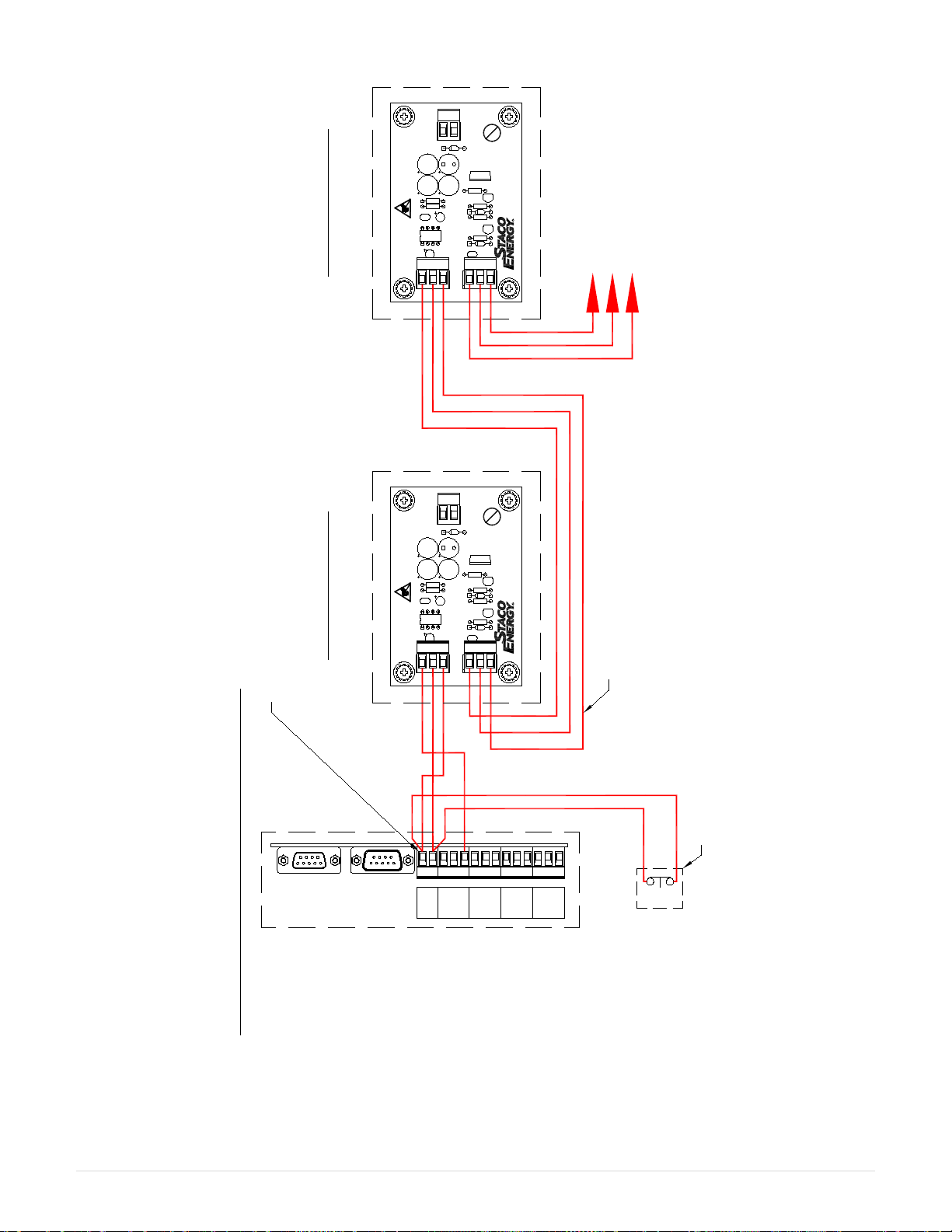
Figure 8- Battery Cabinet to the UPS Remote Emergency Power Off (REPO) Switch Interface
141312114321 5 6 7 8 109
REMOTE COMMANDS AND ALARMS CONNECTIONS
ON FRONT OF UPS BEHIND DOOR
NORMALLY CLOSED
REPO SWITCH
BYPASS
FAULT BATT.
ON BATT.
LOW EPO
INV.
OFF
U1 TB3
TB2
TB1
R7
R6R5R4
R1 R2
Q2
Q1
Q3
D4D3
D2
C8
C3 C6
C5C4
C2
C1
SENSITIVE DEVICE
ELECTROSTATIC
ATTENTION
123
1 2
1 2 3
R
PRODUCTS CO.
BATTERY CABINET #1
CIRCUIT BREAKER INTERFACE BOARD
IN REAR OF CABINET
U1 TB3
TB2
TB1
R7
R6R5R4
R1 R2
Q2
Q1
Q3
D4D3
D2
C8
C3 C6
C5C4
C2
C1
SENSITIVE DEVICE
ELECTROSTATIC
ATTENTION
123
1 2
1 2 3
R
PRODUCTS CO.
BATTERY CABINET #2
CIRCUIT BREAKER INTERFACE BOARD
IN REAR OF CABINET
TO BATTERY CABINET #3
IF PRESENT
ALL WIRING IS INSTALLER PROVIDED
AND SHOULD BE WELL PROTECTED.
WIRE SHOULD BE 1,5 mm² MAXIMIUM
TO 0,34 mm² MINIMUM INSULATED COPPER.
REPO MAY BE WIRED AS SHOWN OR TO TB2 TERMINALS
2 AND 3 OF THE BATTERY CABINET INTERFACE BOARD.
REMOVE AND DISCARD JUMPER
AT TERMINALS 13 AND 14.
FLU-P SHUNT TRIP BOARD
ASSY NO.: 825-0593-LF
Pb
FLU-P SHUNT TRIP BOARD
ASSY NO.: 825-0593-LF
Pb

9 | Page
3 Operation
Refer to the UPS manual for operating instructions. Please note that the breaker in the battery cabinet
must not be operated until the UPS has started and the display no longer shows the message: "Wait: DO
NOT connect the BATTERY". If the breaker has been improperly operated, a qualified service person
needs to check for blown fuses or other damage.
If the UPS is stopped (turned off), the breaker may be left in the closed position for a short period of time.
The safety circuits in the UPS represent a slight current drain on the battery that can lead to severe
depletion of charge, if the battery remains connected to a non-operating UPS. This can lead to battery
damage over the course of several days.
It is recommended to disconnect the batteries if the UPS is to remain off for any significant period of time.
Also, it is not safe to work within the UPS unless all of the batteries are disconnected.
4 UL924 Emergency Lighting Systems
The Staco Battery cabinet can be used as part of an approved UL924 Emergency Lighting system.
Table 1– Battery Models approved for UL924
MODEL
CSB
FIAMM
FLU-P-BAT-540-1
HRL 12540W
12FLX540
Table 2– UL924 Approved Systems
Staco UL924
Model # kW Staco UPS
Model # # of Battery
Cabinets required
FLU-P-924-58
58.5kW
FLU-065
2
FLU-P-924-72
72kW
FLU-080
3
FLU-P-924-90
90kW
FLU-100
3
FLU-P-924-112
112.5kW
FLU-125
4
FLU-P-924-144
144kW
FLU-160
5
FLU-P-T-924-144
144kW
FLU-160-T
5
FLU-P-924-180
180kW
FLU-200
6
FLU-P-T-924-180
180kW
FLU-200-T
6
FLU-P-924-225
225kW
FLU-250
8
FLU-P-T-924-225
225kW
FLU-250-T
8

10 | Page
5 Battery Removal, Installation, and Service
Servicing of batteries should be performed or supervised by personnel knowledgeable of batteries and
the required precautions. Keep unauthorized personnel away from batteries. Always wear eye protection
and have eye wash near at hand. Never work on any connections that have not been disconnected from
all other sources of voltage. Parallel connected battery cabinets require that all battery strings in all
battery cabinets be disconnected before working within any particular cabinet.
Before servicing batteries, the UPS should be turned off, power should be removed from the UPS input,
and all battery breakers should be open. If a Maintenance Bypass Switch (MBS) is present, power to the
load can be maintained during service. Refer to the instructions for the MBS to put the system in bypass
mode before removing power from the UPS.
If it is necessary to remove the cables from the batteries, the connections should be marked in a way that
no confusion will exist when it is time to reconnect the cables (see Figure 10).
Figure 9- Battery Layout
If batteries are being replaced, only use the same manufacturer and battery type and rating as the
battery removed - see Table 10. When the bus bars connecting the batteries are removed, be careful to
avoid dropping bolts or shifting the bus bars so that they might short across adjacent battery terminals.
We recommend using a piece of electrical insulating paper (for example, “Nomex”) as a temporary shield
between the bus bars during service.
If the batteries are to be removed, always remove the highest batteries first. The battery are very heavy
and it will be necessary to use a lifting device to support the batteries as they are removed.

11 | Page
6 Maintenance
The FirstLine P Battery Cabinet is designed to be virtually user maintenance free, requiring only the
occasional wipe with a damp cloth or non-abrasive cleaner.
Spare parts kits are available for the FirstLine Battery Cabinet series, please contact Staco Energy
Products Co. service center for details.
For maximum availability of the UPS, the batteries should be replaced as part of a comprehensive
preventive maintenance program:
Table 3– Battery Replacement Quantities
REPLACEMENT BATTERY
Cabinet Model
Quantity Required
FLU-P-BAT-200-1
40
FLU-P-BAT-200-2
80
FLU-P-BAT-390-1
40
FLU-P-BAT-540-1
40
Table 4– Recommended Replacement Intervals
RECOMMENDED REPLACEMENT INTERVALS
Batteries
2 to 5 years
This product contains Valve Regulated Sealed Lead Acid Batteries.
These batteries contain lead, a neurotoxin, and sulfuric acid, a corrosive. Additionally, the energy stored
in the batteries can present a shock hazard and a burn hazard. Batteries should only be serviced by
trained personnel. Appropriate safety precautions must be observed, including eye protection and skin
protection. Contact with electrolyte requires flushing with generous amounts of clean water. Seek
medical attention immediately following contact with electrolyte. Unwanted batteries must be recycled
and should never be discarded.
The functional lifetime of batteries is significantly affected by the temperature at which they are stored
and operated. Ideally, batteries should be used in a 21º C (70º F) environment. For every 8.3º C (15º F)
increase in temperature, the life expectancy of a battery will be halved.
Exposure to temperatures in excess of 32º C (90º F) should be limited to no more than 30 days per year.
Under no circumstances should the battery be exposed to temperatures over 40º C (104º F) which can
lead to thermal runaway, a condition that damages the battery. Thermal runaway can cause batteries to
swell. If the battery cases burst, the hazardous contents may be exposed.
Maintaining proper ambient temperature usually requires installing the product in a temperature
controlled space. Equipment rooms without cooling systems do not generally maintain the proper
conditions for good battery life.
See Staco’s website for warranty details:
http://www.stacoenergy.com/support/literature-download-center.html

12 | Page
Figure 10 – Typical Cabinets Schematic

13 | Page
7 Specifications
Table 5– Factory Breaker & Fuse settings
MODEL
Breaker
Fuse
FLU-P-BAT-200-1
200
200
FLU-P-BAT-200-2
300
(2) 150
FLU-P-BAT-390-1
400
400
FLU-P-BAT-540-1
600
600
FLU-P-BAT-620-1
600
600
I1: Set to max
I3: set to max
Table 6- Input / Output Cable Size and Torques
Wire Size
Torque
Hardware
(2) 350kcmil
380 lb-in
Compression lug
NOTE 1: It is recommended to use 75°C copper wire.
NOTE 2: Recommended cable sized based on THW cables at 30°C ambient (NEC Table 310.16). If different
cables are used or installed at higher ambient, the cable size need to be reviewed.
NOTE 3: Any external battery wires use reinforced insulation or double insulated wire.
Table 7- Ground Cable Size and Torques
Min Wire Size
Torque
Hardware
#1 AWG
80-90 lb-in
¼-20 screw
Table 8- Circuit Breaker Interface Board Cable Size and Torques
Wire Size
Torque
Hardware
# 22-12 AWG
4.4 lb-in
¼-20 screw
Table 9- Model Floor Loadings
MODEL
Weight (lbs)
Point Loading
FLU-P-BAT-200-1
1, 950
19.2 lb/in2
FLU-P-BAT-200-2
3, 500
34.5 lb/in2
FLU-P-BAT-390-1
3, 300
32.5 lb/in2
FLU-P-BAT-540-1
4, 400
43.4 lb/in2
Table 10 – Battery Models
MODEL
CSB
FIAMM
FLU-P-BAT-200-1
HRL 12200W
12FLX200
FLU-P-BAT-200-2
HRL 12200W
12FLX200
FLU-P-BAT-390-1
HRL 12390W
12FLX400
FLU-P-BAT-540-1
HRL 12540W
12FLX540
Other manuals for FirstLine P
3
This manual suits for next models
1
Table of contents


