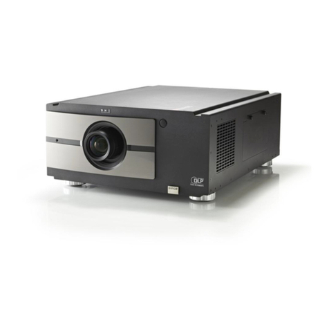
StagePro SP LC 10 W User manual

Multimedia
projector
Owner's Manual
P/N:41
00164500
SP LC 10 W

Statement
Note:
•
The screen menu and pictures inthe manual may slightly differ from the real product.
•
The manual is subject to change without prior notice.
-
1
-


2
Table of Content
s
Table of Contents . . . . . . . . . . . . . . . . . . . . . .2 Computer Input . . . . . . . . . . . . . . . . . . . . . .27
To the
Owner
. . . . . . . . . . . . . . . . . . . . . . . . . .3
Input Source Selection (Computer 1/2)
27
Safety Guide . . . .
.
. . . . . . . . . . . . . . . . .
. . . .5
Computer System Selection
29
Air Circulation
6
Auto PC Adjustment
30
Installing the Projector in Proper Directions
6
Manual Adjustment
31
Moving the Projector
6
Selecting Image Mode
32
Part Names and Functions . . . . . . . . . . . . . .7
Front 7
Adjusting Image 33
Adjusting Screen Size 34
Back
7
Video Input . . . . . . . . .
. . . . . . . . . . . . . . . . .35
Bottom
7
Selecting Input Source
35
Rear Terminal
8
Selecting AV System
36
Side control and indicators
9
Selecting image mode
37
Remote Control
10
Adjusting Image
38
Remote Control Battery Installation
12
Adjusting Screen Size
39
Operating Range
12
Setting. . . . . . . . . . . . .
. . . . . . . . . . . . . . . . .40
Installation. . . . . . . . . . . . . . . . . . .
. . . . . . . .13
Setting
40
Positioning the Projector
13
Information . . . . . . . . .
. . . . . . . . . . . . . . . . .48
Feet Shift Adjustable
13
Display Input Source
48
Connecting to a Computer 14
Connecting to Video Equipment 15
Connecting to Audio Equipment 16
Maintenance and Cleaning . . . . . . . . . . . . .49
Warning Temper indicator 49
Cleaning the Filters 50
Connecting the AC Power Cord 17
Lens installation 18
Resetting the Filter Counter
50
Covering the lens properly
51
Basic Operation . . . . . . . . . . . . . . . . . . . . . .19
Cleaning the Lens
51
Turning On the Projector 19
Cleaning the Projector’s Shell
51
Turning Off the Projector 20
Replacing the lamp
52
How to Operate the On-Screen Menu 21
Maintenance . . . . . . . . . . . .
. . . . . . . . . . . .53
ShortCut Menu 21
Changing the lamp model
53
Full Menu 21
Appendix . . . . . . . . . . . . . . .
. . . . . . . . . . . .54
Full Menu Bar 22
Troubleshooting
54
Zoom and Focus Adjustment 23
Indicator and project state
57
Auto Setup Function 23
Campatibel PCs
58
Keystone 23
Configurations of Terminals
59
Sound Adjustment 24
Remote Control Operation 25 PIN Code memorandum 59
Technical Specifications 60
Outer Dimensions 61
Optional parts 62

3
Caution
Electric shock
Do not open
Caution: To reduce the risk of electric shock, do not
remove the cover (or back). No
user-serviceable parts inside except lamp
replacement. Refer servicing to qualified
service personnel.
The sign indicates the danger of high voltage,
i.e., electric shock.
The sign indicates important operating and
maintenance instructions in the manual with the
unit.
10
Please read this manual completely before installing and
operating the projector.
The projector provides many convenient features and
functions. Proper operation may enable you to fully utilize
the features and keep it in good condition. Otherwise, it
will not only shorten the service life of the unit, but also
may cause malfunction, a fire, or other accidents.
If your projector cannot work properly, please read this
manual again, check the operating methods and cable
connection, and try the solutions in the part of
Troubleshooting. If the problem still exists, contact the
dealer or the service center.
The lamp of the projector is a wearing part. The luminance
may decrease after a period of operation and be weaker
than that of a new lamp. This is normal. Please strictly
follow the steps in Turning on the unit and Turning off the
unit to turn on/off the projector, and the requirements in
Maintaining and cleaning the projector to service and clean
the projector regularly. Or the high temperature residual
heat may not radiate, greatly shortening the service life of
the projector and lamp, or even damaging them within a
short period.
Safety precautions
Ca
u
t
ion
:●
The projector must be grounded.
●Do not expose the projector to raindrops or high
humidity to avoid a fire or electric shock.
-- This projector produces intense light from the projection
lens. Avoid staring directly into the lens, otherwise eye
damage could be caused. Be especially careful that
children do not stare directly into the beam.
-- Place the projector in a proper position. Otherwise it
may result in fire hazard.
--Leave an appropriate space from the top, sides, and back
of the shell in order to ventilate and cool down the
projector. The figures below indicate the minimum
distance to be left. It must be satisfied if the projector is
placed in sealed environment like a cabinet.
20cm
1m
50cm
1m
--Do not cover the vent of the projector. Poor radiation
may shorten the service life or even cause dangers.
--Remove the AC power plug if the projector is not to be
used for a long time.
--Do not project the same image for a long time; otherwise,
a residual image may appear on the LCD panel due to its
characteristic.
Caution
Do not set the projector in greasy, wet, or smoky
conditions such as in a kitchen, to prevent a malfunction or
accident. If the projector comes in contact with oil or
chemicals, it may become deteriorated.
Read and keep this manual for future reference.
Environment-friendly use conditions: The
environment-friendly life
t
ime
of
the
projector and remote control is 10 years, the
lamp (consumable)
5 years, and
the
provided batteries (consumable) 5 years.
The use conditions of the
environment-friendly use period are the
same with that of the product. Properly
operate and effectively
maintain
the
projector according to the requirements in
this manual.

4
To the owner
Safety guide
All the safety and operating instructions should be read
before the product is operated.
Read all of the instructions given here and retain them
for later use. Unplug this projector from AC power supply
before cleaning. Do not use liquid or aerosol cleaners.
Use a damp cloth for cleaning.
Follow all warnings and instructions marked on the
projector.
For added protection to the projector during a lightning
storm, or when it is left unattended and unused for long
periods of time, unplug it from the wall outlet. This will
prevent damage due to lightning and power line surges.
Do not expose this unit to rain or use near water... for
example, in a wet basement, near a swimming pool, etc...
Do not use a
t
t
achmen
t
s not recommended by
t
he
manufacturer as they may cause hazards.
Do not place this projector on an unstable cart, stand,
or table. The projector may fall, causing serious injury
to a child or adult, and serious damage to the projector.
Use only with a cart or stand recommended by the
manufacturer, or sold with the projector. Wall or shelf
mounting should follow the manufacturer’s instructions,
and should use a moun
t
ing kit approved by
t
he
manufacturers.
An appliance and cart combination
should be moved with care. Quick
stops, excessive force, and uneven
surfaces may cause the appliance and
cart combination to overturn.
Slots and openings in the back and bottom of the cabinet
are provided for ventilation, to ensure reliable operation of
the equipment and to protect it from overheating.
Never push objects of any kind into this projector
through cabinet slots as they may touch dangerous
voltage points or short out parts that could result in a
fire or electric shock. Never spill liquid of any kind on the
projector.
Do not install the projector near the ventilation duct of
air-conditioning equipment.
This projector should be operated only from the type
of power source indicated on the marking label. If you
are not sure of the type of power supplied, consult your
authorized dealer or local power company.
Do not overload wall outlets and extension cords as this
can result in fire or electric shock. Do not allow anything
to rest on the power cord. Do not locate this projector
where the cord may be damaged by persons walking on
it.
Do not attempt to service this projector yourself as
opening or removing Covers may expose you
t
o
dangerous voltage or other hazards. Refer all servicing
to qualified service personnel.
Unplug this projector from wall outlet and refer servicing
to qualified service personnel under the following
conditions:
a. When the power cord or plug is damaged or frayed.
b. If liquid has been spilled into the projector.
c. If the projector has been exposed to rain or water.
d. If the projector does not operate normally by
following the operating instructions. Adjust only those
controls that are covered by the operating instructions
as improper adjustment of other controls may result
in damage and will often require extensive work by a
qualified technician to restore the projector to normal
operation.
e. If the projector has been dropped or the cabinet has
been damaged.
f. When the projector exhibits a distinct change in
The openings should never be covered with cloth or other
materials, and the bottom opening should not be blocked
by placing the projector on a bed, sofa, rug, or other
similar surface. This projector should never be placed
near or over a radiator or heat register.
This projector should not be placed in a built-in installation
such as a book case unless proper ventilation is provided.
performance-this indicates a need for service.
When replacement parts are required, be sure the
service technician has used replacement parts specified
by the manufacturer that have the same characteristics
as the original part. Unauthorized substitutions may
result in fire, electric shock, or injury to persons.
Upon completion of any service or repairs to this
projector, ask the service technician to perform routine
safety checks to determine that the projector is in safe
operating condition.

5
Safety
guide
Air circulation
Openings in the cabinet are provided for ventilation. To
ensure reliable operation of the product and to protect it
from overheating, these openings must not be blocked or
covered.
Caution
Hot air is exhausted from the exhaust vent. When using
or installing the projec
t
or
,
the following precautions
should be taken.
--Do not put any flammable objects, or spray can near
the projector. Hot air is exhausted from the air vents.
--Keep the exhaust vent at least 1 m away from any
objects.
--Do not touch a peripheral part of the exhaust vent,
especially screws and metallic part. This area will
Installing the projector in proper directions
Install the projector properly for normal operation.
Improper installation may reduce the lamp lifetime and
cause a fire hazard. The projector may project images
upward, downward, or slantwise when it is installed
vertically to the surface level. Keep the bottom of the
projector upward for installation when it is tilted
downward.
To flip an image, set the ceiling function ON.
Positioning precautions
10
˚
Do not roll the projector over 10
become hot while the projector is being used.
--Do not put anything on the projector. Objects put on the
cabinet will not only get damaged but also may cause
fire hazard by heat.
Cooling fans are provided tocool down the projector.
The fan’s running speed is changed according to the
temperature inside the projector.
10
˚
degrees from side to side.
Do not point the projector down to
project an image.
10°
10
°
Air intake vent
Air intake vent
Do not roll the projector over 10 degrees from
side to side when projecting an image upward.
Do not tilt the projector over 10 degrees from
side to side when projecting an image downward.
10°
10
°
Air intake vent
Exhaust vent Caution on ceiling mounting
For ceiling mounting, you need the ceiling mount kit
designed for this projector.When not mounted properly,
the projector may fall, causing hazards or injury. For
details, consult your dealer. The warranty on this
projector does not cover any damage caused by use of
any non-recommended ceiling mount kit or installation
of the ceiling mount kit in an improper location.

To the owner
6
Safety
guide
Moving the projector
Caution on lens protector
Before use, remove the lens protector. To move the projector, press and
hold the Shift or lens key more than 5 seconds to center the lens back.
Then, install the protector to protect the lens.
Lens protector
When moving the projector, retract the adjustable feet to prevent damage to the lens and cabinet.
Put it into a suitable case when the projector is not in use for a long period.
Caution in moving or transporting the
p
r
oj
ect
o
r
–Do not drop or bump the projector, otherwise damages or malfunctions may result.
–When carrying the projector, use a suitable carrying case.
–Do not transport the projector by courier or any other transport service in an unsuitable transport
case. This may cause damage to the projector. For information about transporting the projector by
courier or any other transport service, consult your dealer.
–Do not put the projector in a case before it is cooled enough.
Caution in handling the projector
When lifting or moving the projector, do not hold the lens
or the directive hood to prevent damage to the lens or the
unit.
Handle the projector with care. Do not drop or bump it to
avoid strong force, or place other objects on the cabine
t.
Caution
The lens of the projector is electric.
When operating the projector, pay
attention to the following conditions.
When the lens is rotating, do not
touch it, otherwise your fingers may
get hurt.
Do not allow a child to touch the lens.
Do not hold the lens and the peripheral part.

7
Part names and functions
⑧②①
③
Front
⑥
⑩
⑨
⑤④
⑦
(1) Lens release button
(2) Indicator
(3) Lamp cover
(4) Speaker
(5) Lens cap
(6) Projector lens
(7) Decorative cover
(8) Remote receiver (Front & top)
(9) Side control panel
Back ⑫ ⑪
⑩
(10) Exhaust vent
Caution
Hot air is exhausted from the exhaust vent. Do
not put heat-sensitive objects near this side.
Back ⑬
(11) Remote receiver (Back)
(12) Terminals and connectors
(13) Air filter and air-intake vent
(14) Power cord connector
Bottom
(15) Safety lock
(16) Adjustable feet

7


Part names and functions
8
Rear terminal
1 2 3 4 5
6 7 89 10 11 12
(1) Network port
Used to connect the network cable.
(2) COMPUTER IN2/MONITOR OUT
- Used to connect the computer output.
- Used to output the analog signals from (3) or
(6) to the other monitor.
(3)COMPUTER IN1/SCART IN
- Used to connect a computer or RGB SCART
output.
(4) DVI
Used to connect the DVI digital output.
(7) S-VIDEO
Used to connect the S-video output of video
equipment.
(8) Composite (video) input jacks
Connect the composite signals to this
terminal.
(9) AUDIO IN3
Connect the audio to these jacks, When Video
equipment connected to INput3.
(10) AUDIO IN2
Connect the audio to this jack (stereo), When Video
equipment connented to INput2
(5) HDMI
Used to connect the HDMI digital output.
(11) AUDIO OUT
Used to output the audio from (9) or (10) or (15).
(6) BNC jacks
Connect the component video output to Y, Cb
Cr or composite video output from video
equipment to VIDEO 2 terminal, or connect
the RGBHV format (5 line system) signal
to G, B, R, Hs, and Vs jacks.
(12) CONTROL
When using RS232 to control the projector,
please connect the serial control line to this
terminal.

9
Part names and functions
Side control and indicators
Side control Indicators (Top panel)
4
(1) SELECT button
–Enter full menu from shortcut.
–Execute the selected item.
–Expand or compress the image in the Digital zoom
Mode.
(9) Point ▲▼◄► (VOLUME +/–) buttons
–Select an item or adjust the value in the
On-Screen Menu.
–Pan the image in the D. Zoom +/- mode.
–Adjust the volume level.
(2) INPUT button
To select an input source.
(3) SHIFT button
To enter the lens shift mode.
(4) AUTO SETUP button
To perform various settings configured
automatically, including the input source
search function and auto PC adjustfunction.
(5) ZOOM button
To zoom in/out images.
(6) MENU button
To open or close the screen menu.
(7) FOCUS button
To adjust the focus.
(8) ON/STAND-BYbutton
To turn on/off the projector.
(10) POWER indicator
–Lights red when the projector is in stand-by
mode.
–Lights green during operations.
–Flashes green in the Power management mode
(11) LAMP REPLACE indicator
It turns orange when the life of the projection
lamp draws to an end.
(12) WARNING TEMP indicator
It flashes red when the internal projector
temperature is too high.
(13) SHIFT indicator
It lights blue when the projector lens is
moving.
It lights blue when the projector lens is
moving to the end.
(14) FOCUS indicator
It lights green when zooming in/out.

Part names and functions
10
Remote control
①
/DVI
②
①ON-STANDBY button
Turn the projector on or off.
②HDMI/DVI button
Select HDMI or DVI input source.
③⑤
④③ COMPUTER
button
⑥⑨Select VGA1 or VGA2 input source.
⑦⑧④ RGBHV button
⑪Select RGBHV input source.
⑩
⑬⑭⑤
SCART
button
⑫⑮Select SCART input source.
⑯⑱
⑲⑥
VIDEO 1 button
⑰Select VIDEO 1 input source.
26
27 ⑦
VIDEO 2
button
29 Select VIDEO 2 input source.
25
28 ⑧
S-VIDEO button
Select the S-Video input source.
⑨
COMPONENT button
Select the component input source.
⑩
▲▼◄►
bu
tt
on
–Select an item or adjust the value in the
on-screen menu.
–Pan the image in Digital zoom + mode.
⑪SELECT
bu
tt
on
-Access the full menu or select an item in the
menu.
⑫S.MENU
bu
tt
on
Open or close the shortcut menu.
⑬
F.MENU
bu
tt
on
Open or close the full screen menu.
⑭
KEYSTONE
button
Calibrate keystone type distortion.
⑮
TIMER
button
Enable the timer function.

Part names and functions
11
⑩
Remote control
⑯
LENS
bu
tt
on
Select the lens shift mode.
①
⑰
ZOOM
button
Zoom in/out images.
/DVI
②
⑱
FOCUS button
③⑤Adjust the focus.
④
⑥⑨⑲
LAMP button
⑦⑧Select the lamp mode.
⑪⑳SCREEN
bu
tt
on
⑭Select a screen display mode.
⑬
⑫⑮D.ZOOM-
bu
tt
on
⑯⑱
⑲Select the digital zoom - mode.
⑰
26 BLANK
bu
tt
on
27 Temporarily close the on-screen imag
e.
29 FREEZE
25
button
Freeze the projected image.
28
To ensure safe operation, observe
the following precautions:
–Do not bend, drop, or expose the remote
control to moisture or heat.
–For cleaning, use a soft dry cloth. Do not
apply benzene, thinner, splay, or any other
chemicals.
AUTOSET button
Enter the AUTOSET mode.
25 D.ZOOM+ button
Select the digital zoom + mode.
26
MUTE button
Mute the sound.
27 IMAGE
bu
tt
on
Select the image mode.
28 VOLUME-
bu
tt
on
Decrease the volume level.
29
VOLUME+ bu
tt
on
Increase the volume level.

Part names and functions
12
Remote control battery installation
1
Open the ba
ttery
compartment li
d.
2 Install new batteries into the
compartment. 3 Replace the compartment
lid.
For correct polarity (+
and –), be sure
battery terminals are in
contact with pins in the
compartment.
To ensure safe operation, please observe the following precautions:
●Use two (2) AAAor LR03 type alkaline batteries.
●Always replace batteries in sets.
●Do not use a new battery with a used battery.
●Avoid contact with water or liquid matter.
●Do not expose the remote control to moisture or heat.
●
Do not drop the remote control.
●
If the battery has leaked on the remote control, carefully
wipe the case clean and install new batteries.
●
Risk of explosion if a battery is replaced by an incorrect type.
●
Dispose of used batteries according to the instructions. 5M
Operating range
Point the remote control toward the projector when pressing any
button. The maximum operating range for the remote control is
about 5 meters and 60 degrees.
5M
Adjustable feet
Projection angle can be adjusted up to 5.0 degree with the
adjustable feet.
Rotate the adjustable feet to lift the projector to a certain height.
During lifting, rotate the two feet clockwise.
To lower or retract the adjustable feet, rotate the two feet
counterclockwise.
Keystone distortion of the projected image can be corrected by
menu operation.
Adjustable feet

Part names and functions
13
Positioning the projector
√Note
The brightness in the room has a great influence on picture quality. It is recommended to limit the ambient lighting
in order to get the best image.
All measurements are approximate and may vary from the actual sizes.
17.481 m (Diagonal)
7.974 m
5.301 m
2.628 m
10.647 m
Max. frame
Min. frame
400”
40”
100”
200”
300”
400”
813 x 610
2032 x 1524
4064 x 3048
6096 x 4572
8128 x 6096
1.024 m
2.628 m
5.301 m
7.974 m
10.647 m
1.705 m
4.334 m
8.716 m
13.098 m
17.481 m
WIDE
18.187 m (Diagonal)
8.489 m
5.645 m
2.8 m
11.319 m
Max. frame
Min. frame
400”
16:10
40”
100”
200”
300”
400”
862 x 539
2154 x 1346
4308 x 2692
6462 x 4039
8616 x 5385
1.093 m
2.8 m
5.645 m
8.489 m
11.319 m
1.777 m
4.514 m
9.077 m
13.64 m
18.187 m
Lens shift adjustment
Projection lens can be moved from side to side and up an
function makes the positioning of images easy on the screen.
The display
position can be
shifted upward up
to 50% elevation
of the display. The display
position can be
shifted downward
up to 50%
elevation of the
display
.
When the lens is shifted totop. When the lens is shifted to bottom.
Adjusting range
50%
10%
The display
position can be
shifted to the left
up to 10% width
of the display.
The display position can
be shifted to the right up
to 10% width of the
display.
When the lens is
Shifting range
When the lens is shifted to leftmost. When the lens is shifted to rightmost. shifted to the center.

14
Installation
Installation
Connecting to computer (Digital and analog RGB)
Cables used for connection ( =Cables are not supplied with the projector.)
•VGA cable (1) •Serial crossover cable (F-F) *
• BNC cable * • HDMI cable *
Monitor output
BNC cable
Serial output Monitor input * Monitor output HDMI terminal
VGAcable VGAcable DVI cable HDMI cable
Serial output
G B R H V
Control terminal Analog output Analog input
HDMI
Serial
crossover
cable
DVI Control port
Unplug the power cords of both the projector and external
equipment from the AC outlet before connecting the cables.

Installation
15
Connecting to video equipment
Cables used for connection (*=Cables are not supplied with the projector.)
•Video cable (RCA* 1 or RCA*3) *
•BNC cable (BNC*1 or BNC*3) *
•
•S-Video cable *
Scart-VGAcable *
Composite
video
Refer to the
analog outpu
signal table as
shown in the
figure above.
Component
video output
Composite
video
RGBScart21-pin
output
S-video
output
RC
A
Scart-VGA S-video
cable
cable cable
Video
Video
Analog otput
Y - Pb/Cb - Pr/Cr video
Analog input
S-VIDEO
DVI
Unplug the power cords of both the projector and external equipment from the
AC outlet before connecting the cables.

Installation
16
Connecting to audio equipment
Cables used for connection (* =Cables are not supplied with the projector.)
Audio cable *
External audio equipment
Audio output
Audio output (R) (L)
(R) (L)
Audio input
or
Audio cable
(Stereo) Audio cable
(
St
ereo)
Audio IN
Audio cable
(R) (L)
Audio cable
(
St
ereo)
Audio cable
(
St
ereo)
Unplug the power cords of both the projector and external
equipment from the AC outlet before connecting
the cables.
Table of contents
