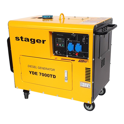
Stager YDE12000E User manual

Pastrati acest manual pentru referinte viitoare
Traducere a Instructiunilor Originale
GENERATOR DE CURENT DIESEL
MANUAL DE UTILI ARE • USER MANUAL
MODELE: □ Monofazat: YDE12000E • YDE12000T • YDE15000T
□ Trifazat: YDE12000E3 • YDE12000T3 • YDE15000T3
Atat numarul modelului, cat si seria pot fi gasite pe eticheta principala cu date tehnice.
Ar tre ui sa le inregistrati pe amandoua intr-un loc sigur pentru utilizari ulterioare.
PENTRU SIGURANTA DUMNEAVOASTRA
VA RUGAM SA CITITI SI SA INTELEGETI ACEST MANUAL INAINTE DE UTILI AREA PRODUSULUI. ACEST MANUAL
CONTINE INFORMATII IMPORTANTE PENTRU FUNCTIONAREA IN CONDITII DE SIGURANTA A ECHIPAMENTULUI.
Ver. 3/Rev. 2; Data: 8.08.2022 1

EN: Save this manual for future reference
Original Instructions
PREFACE
Thank you for purchasing STAGER Diesel Generator Set Series.
This manual contains information for the correct operation and maintenance of your generator set. It
also contains important safety and installation information, trou leshooting guidelines. Thoroughly
read this operation manual efore operating the generator set.
Please always keep this manual with the equipment.
Please operate this equipment after thoroughly reviewing and understanding the contents of this
manual. The owners and operators of the generator set are solely responsi le for it’s safe operation.
The information contained in this manual was ased on the genset in production at the time of
pu lication. We reserve the right to make changes at any time without notice and without incurring
any o ligation.
Without express written permission from us, any part of this manual can not e reproduced in any
form or y any means.
Please read the manual carefully efore using the engine.
This guide contains important guidance for safe operation.
Ver. 3/Rev. 2; Data: 8.08.2022 28

CONTENT
PREFACE …………………………………………………………………………………………………………………..
1. IMPORTANT SAFETY INSTRUCTIONS …………………………………………………………………………….
1.1 Overview ………………………………………………………………………………………………………….
1.2 Safety sym ols …………………………………………………………………………………………………...
1.3 General Safety Precautions …………………………………………………………………………………….
2. MAIN TECHNICAL SPECIFICATION ………………………………………………………………………………...
3. MAIN PARTS ……………………………………………………………………………………………………………
3.1 Parts illustration (Open frame type) .…...….....……......…...……......…...........……...….…….…………...
3.2 YDE12000T/T3 Parts illustration (Silent type) …………………………..…………………………………….
3.2 YDE15000T/T3 Parts illustration (Silent type) ………………………………………………………………..
4. PREPARATION FOR STARTING …………………………………………………………………………………….
4.1 Installation of exhaust pipe ……………………………………………………………………………………..
4.2 Fuel selection and use .……….....…......….....………..…............…....…..............................…………….
4.3 Check and refilling engine oil …...............…...…......….…...........…….......…………………..……..……..
4.4 Service the air filter …………………………..….....………….……………………………………….……….
4.5 Check the generator set ………………………………………….…………………………………….……….
5. START THE GENERATOR SET ……………………………………….……………………………….…………….
5.1 Electric starting …………….……………………………………………………………………………………..
5.2 Control panel …………………...……………….………………………………………………………………..
6. OPERATE THE GENERATOR SET ………………………………………………………………………………….
6.1 Operation of generator set …………………………………..………………………………………………….
6.2 Inspection during running ……………………………………………………………………………………….
6.3 Break-in period ……….…………………………………………………………………………………………..
7. LOAD …………………………………………………………………………………………..………………………..
7.1 AC application …..……………………………………………………………………………………………….
7.2 Single output from three-phase generator ……...…………………………………………………………….
7.3 Electrical appliance ……...………………………………………….........……….…………………………….
8. STOPPING THE GENERATOR ……………………………………………………………...………………………
8.1 Normal shutdown .....….…..……..…….......…....…..................…..........….......……..……...……..……….
8.2. Emergency stop ........……..……..………………..……..……...............…..………..….......……..………...
9. PERIODIC CHECK AND SERVICE .................................................................................................................
9.1. Maintenance schedule ..............................................................................................................................
9.2. Replace engine oil .....................................................................................................................................
9.3. Clean engine oil filter .................................................................................................................................
9.4. Replace air filter element ..........................................................................................................................
9.5. Clean and replace fuel filter ......................................................................................................................
10. LONG-TERM STORAGE ................................................................................................................................
11. TROUBLESHOOTING ...................................................................................................................................
12 APPENDIX .......................................................................................................................................................
13. ELECTRIC DIAGRAM ....................................................................................................................................
13.1. Electric diagram for single-phase model .................................................................................................
13.2. Electric diagram for three-phase model ..................................................................................................
Declaration of conformity
...........................................................................................................................................
28
30
30
30
30
33
35
35
36
37
38
38
39
39
40
40
42
42
42
44
44
44
45
45
45
46
46
47
47
47
47
47
48
48
49
49
49
49
51
52
52
53
54
Ver. 3/Rev. 2; Data: 8.08.2022 29

1. IMPORTANT SAFETY INSTRUCTIONS
1.1 Overview
Thoroughly read this operation manual efore operating the generator set. It contains important instructions
that should e followed during operation and maintenance. Safe operation and top performance can only e
achieved when equipment is properly operated and maintained. The owners and operators of the generator
set are solely responsi le for it’s safe operation.
Generator set operation, maintenance, and installation must comply with all applica le local regulations.
Electricity, fuel, exhaust, moving parts and atteries present hazards which can result in severe personal injury
or death. Only trained and experienced personnel with knowledge of fuels, electricity, and machinery hazards
should perform generator set installation or adjustment procedures; or remove, dismantle the generator set.
1.2 Safety symbols
The following sym ols are applied in the manual indicate potentially hazardous conditions to the
operators, service personnel, or the equipment.
DANGER
Indicates a hazardous situation that, if not avoided, will result in death or serious injury.
WARNING
Indicates a hazardous situation that, if not avoided, could result in death or serious injury.
CAUTION
Indicates a hazardous situation that, if not avoided, could result in minor or moderate injury.
NOTE
Indicates information considered important, ut not hazard-related(e.g., messages relating to property damage).
1.3. General Safety Precautions
To generator set operators
WARNING
•Do not operate the generator when fatigued, or after consuming any alcohol or drug.
•Wear suita le clothing when operating the generator. Loose clothing is easily caught in the moving parts and
cause serious injury.
•Operators must e thoroughly trained efore operating the unit.
•Only suita le trained and experienced service personnel can perform
•electrical and/or mechanical service.
•Do not allow any unauthorized personnel near y the running generator set.
•Keep the generator set out of the reach of the children and pets.
•Pay attention to any a normalities when the generator is running such as vi ration, noise, exhaust smoke color
and leaks. Shut down the generator immediately and trou leshoot efore restarting the generator set.
Fuel and Fumes Are Flammable
WARNING
•Do not fill fuel tanks while the engine is running unless the tanks are outside the engine
compartment. Fuel contact with hot engine or exhaust is a potential fire hazard.
•Do not permit any flame, cigarette, pilot light, spark, arcing equipment, or other ignition source
near the generator set or fuel tank.
•Fuel pipes must e adequately secured and free of leaks. Fuel connection at the engine should
e made with an approved flexi le line. Do not use copper piping on flexi le pipes.
•Flamma le vapor can cause an engine to over speed and ecome difficult to stop, resulting in
possi le fire, explosion, severe personal injury or death. Do not operate the unit in flamma le
and explosive environments.
•Any spillage that occurs during fueling, oil top-off, or oil change must e cleaned up efore
starting the generator set.
Ver. 3/Rev. 2; Data: 8.08.2022 30

Handling Waste
•Do not dispose the waste fuel/oil to the sewer or river to avoid environment
pollution.
•The fuel/oil drained off the machine should e kept in the container.
•Dispose of all wastes properly in accordance with local environmental regulations.
This includes fluids, filters, atteries, electrical components, etc.
Exhaust Gases Are eadly
DANGER
•The generator emits car on monoxide, a colorless, odorless gas which can kill you y
asphyxiation. Do not reather in or come into contact with exhaust gases.
•The generator must e operated outdoors or in well ventilated areas. If the generator is
operated indoors, it must e placed in a well-designed room with proper ventilation.
•Check the exhaust system for corrosion, o struction, and leaks every time efore starting the
generator set and every eight hours when you run the unit continuously. Do not use exhaust
gases to heat a compartment. Make sure that exhaust manifolds are secured and not warped.
Moving Parts Can Cause Severe Personal Injury or eath
DANGER
•Keep hands, clothing, and jewelry away from moving parts.
•Make sure the fasteners on the generator set are secure. Tighten supports and clamps.
Generator guard doors must e completely closed and locked during running.
•Before starting work on the generator set, disconnect the attery charger from its AC source,
then turn off the attery switch. This will prevent accidental starting.
•Do not wear loose clothing or jewelry in the vicinity of moving parts or while working on
electrical equipment. Loose clothing and jewelry can ecome caught in the moving parts.
•If any adjustments must e made while the unit is running, use extreme caution around hot
manifold, moving parts, etc.
•The electric cooling fan may run a few minutes more after the unit stopped. Do inspection or
service only after the fan completely stopped.
Electric Shock and Arc Flashes Can Cause Severe Personal Injury or eath
DANGER
•Never operate the generator in wet conditions. Water will conduct electricity.
•An electric shock resulting in death can occur y touching the output terminals while generator
set is running.
•When connecting the generator to the load, the circuit reaker must e placed in the OFF
position and the generator stopped. (When in parallel operation, any other loads should e
turned off esides this unit)
•The cover of the output terminals must e closed and the screws should e tightened efore
operating the generator
•The generator produces voltage even at low speeds. Ensure the generator stopped completely
efore inspection and service.
•Touching the circuit inside the control panel will lead to electric death. Please close the control
ox and tighten the screws efore running the generator.
•Before opening the control ox, close the circuit reaker and stop the generator. The control
ox contains live current.
•The circuit reaker prevents electric shock injuries. When replacing the circuit reaker, e sure
to use the same specification one.
•The inspection of internal circuits of the control panel can only e performed after stopping the
generator unit and removing the ignition key.
Generator Wiring
CAUTION
•Connections for stand y power to a uilding's electrical system or to the mains must e made y a qualified
electrician and must comply with all applica le laws and electrical codes.
•Improper connections can allow electrical current from the generator to ack feed into the utility lines. Such
ack feed may electrocute utility company workers or others who contact the lines during a power outage, and
when utility power is restored, the generator may explode, urn, or cause fires in the uilding's electrical system.
Ver. 3/Rev. 2; Data: 8.08.2022 31

Earth Ground Connection
CAUTION
The neutral of the generator set may e required to e onded to earth ground at the generator set
location, or at a remote location, depending on system design requirements. Consult the engineering
drawings for the facility or a qualified electrical design engineer for proper installation.
NOTICE
•The end user is responsi le to make sure the ground connection point surface area is clean and free of rust
efore making a connection.
•The end user is responsi le for making sure that an earthing arrangement that is compliant with local conditions
is esta lished and tested efore the equipment is used.
High Temperature
DANGER
•The silent generator set doors must e closed securely when the generator is operating. Do not
get close to or touch the exhaust pipes and mufflers, radiator, cylinder cover, engine lock and
generator housing to prevent severe scald.
•The generator will remain hot for several minutes after shutting down. Inspection and
maintenance of the generator set must e done only after the generator set is fully cooled
down.
•If any check or service must e made while the unit is running, use extreme caution around hot
manifold, moving parts, etc.
•Engine coolant is very hot and under high pressure. Don’t open the radiator cap until the engine
is completely cooled, otherwise steam and hot water will e released and cause severe
personal scald.
•Inspect the coolant level every time efore operating generator set. Service cooling system
efore operating the unit or when the engine is completely stopped and the coolant temperature
falls to 50 C.⁰
Battery
WARNING
•The attery can produce com usti le gas leading to an explosion or serious injury.
•Charge the attery only in a well-ventilated area to prevent an explosion.
•When connecting the attery ca les, connect the positive terminal first and then the negative terminal. O serve
proper polarity to prevent a short circuit or sparks which could ignite the com usti le gas produced y the
attery.
•Turn off the attery switch or disconnect attery when performing maintenance on the generator.
•The electrolyte of the attery is diluted sulfuric acid which can cause severe urns. If electrolyte contacts the
skin or clothing, immediately flush with large amounts of clean water. If electrolyte gets into the eyes, rinse the
eyes with a large amount of water and seek immediate medical treatment.
• Inspect the storage attery after the engine is stopped.
Noise Level of silent generator set
CAUTION
•The noise level of the generator set is significantly increased with the doors open.
•If the unit has to operate with the door open, such as during an inspection, the operator shall
wear protective ear plugs to prevent permanent hearing loss.
Noise instructions:
The noise level listed in this manual is not safety working level ut emission level. There is a linkage
etween emission level and noise level. The emission level cannot e regarded as the standard to
decide whether the noise protection measures need to e taken.
Factors affecting the actual noise level includes the operating am ient conditions and other noise
sources (The quantity of the generators, working hours in the noisy environment, etc.) .
Ver. 3/Rev. 2; Data: 8.08.2022 32

Stacking
CAUTION
•Improper stacking method will cause the generator sets fall down and cause serious accidents.
•The generator must e placed on solid level surface.
•Only one unit may e stacked on another one and the outline dimension and weight of the unit on the top must
e smaller and lighter than the one on the ottom.
•Do not attempt to operate either generator while stacked. The vi ration may cause one or oth generators move
and fall.
Transportation
WARNING
•Lift the generator set with the lifting eye in the middle of the top cover or four lifting eyes at the ottom.
Otherwise the generator set may fall down due to insufficient strength. Or the generator set can e moved y
forklift.
•Don't stand under the generator set while it is lifted up.
•Don't lift or move the generator set in operation.
•Fix the unit properly when it’s transported y the truck.
2. MAIN TECHNICAL SPECIFICATION
Single phase generator sets:
Model
Item
YDE12000E YDE12000T YDE15000T
Rated frequency 50 Hz 50 Hz 50 Hz
Rated power 10 kVA 10 kVA 11 kVA
Maximum power 11 kVA 11 kVA 12 kVA
Rated voltage (CA) 230/115 V 230/115 V 230/115 V
Rated current (CA) 43.5/87 A 43.5/87 A 47.8/95.7 A
Rated speed 3000 r/min 3000 r/min 3000 r/min
Phase no. Single phase Single phase Single phase
Power factor (cos Φ) 1 1 1
Excitation mode AVR (self-excited, automatic voltage regulator)
Insulation class F F F
Pole num er 2 2 2
Connecting Mode Transmission shaft rigid connection
Voltage output (DC) 12V - 36Ah 12V - 36Ah 12V - 36Ah
Starting system 12V electrical starter
Structure mode Open frame Silent Ultra silent
Weight 185 kg 260 kg 260 kg
Dimensions (Lxlxh) 1000 x 630 x 700 mm 1095 X 650 X 780 mm 1095 X 650 X 780 mm
Engine model YD2V88 YD2V88 YD2V92F
Engine type Diesel engine, V-twin, 4-stroke, direct injection, air-
cooled
Diesel engine, V-two, vertical,
4-stroke, air-cooled
Rated power 13.8 kW / 3000 rpm 13.8 kW / 3000 rpm 14.8 kW / 3000 rpm
Bore x Stroke 88x75 mm 88x75 mm 92x75 mm
Displacement 912 ml 912 ml 997 ml
Compression ratio 20:1 20:1 20:1
Cooling system air-cooled air-cooled air-cooled
Lu e oil capacity 2.3 L 2.3 L 2.4 L
Ver. 3/Rev. 2; Data: 8.08.2022 33

Lu e oil type SAE 15W-30, 15W-40 SAE 15W-30, 15W-40 SAE 15W-30, 15W-40
Fuel type Diesel 0#(summer) -10#(winter) -35# (chilly winter)
Fuel tank capacity 25 L 25 L 25 L
Fuel consumption ≤ 340 g/kW.h ≤ 340 g/kW.h ≤ 340 g/kW.h
Noise level (LwA) 97 dB(A) 93 dB(A) 93 dB(A)
Three-phase generator sets:
Model
Item
YDE12000E3 YDE12000T3 YDE15000T3
Rated frequency 50 Hz 50 Hz 50 Hz
Rated power 12 kVA 12 kVA 13 kVA
Maximum power 13 kVA 13 kVA 14 kVA
Rated voltage (CA) 400/230 V 400/230 V 400/230 V
Rated current (CA) 17.3 A 17.3 A 18.8 A
Rated speed 3000 r/min 3000 r/min 3000 r/min
Phase no. three-phase three-phase three-phase
Power factor (cos Φ) 0.8 (lag) 0.8 (lag) 0.8 (lag)
Excitation mode AVR (self-excited, automatic voltage regulator)
Voltage output (DC) 12V - 36Ah 12V - 36Ah 12V - 36Ah
Structure mode Open frame Silent Ultra silent
Insulation class F F F
Pole no. 2 2 2
Connecting Mode Transmission shaft rigid connection
Weight 185 kg 260 kg 260 kg
Dimensions (Lxlxh) 1000 x 630 x 700 mm 1095 X 650 X 780 mm 1095 X 650 X 780 mm
Engine model YD2V88 YD2V88 YD2V92F
Engine type Diesel engine, V-twin, 4-stroke, direct injection, air-
cooled
Diesel engine, V-two, vertical,
4-stroke, air-cooled
Engine rated power 13.8 kW / 3000 rpm 13.8 kW / 3000 rpm 14.8 kW / 3000 rpm
Bore x stroke 88 x 75 mm 88 x 75 mm 92x75 mm
Displacement 912 ml 912 ml 997 ml
Compression ratio 20:1 20:1 20:1
Cooling system air-cooled air-cooled air-cooled
Lu e oil capacity 2.3 L 2.3 L 2.4 L
Lu e oil type SAE 15W-30, 15W-40 SAE 15W-30, 15W-40 SAE 15W-30, 15W-40
Fuel type Diesel 0#(summer) -10#(winter) -35# (chilly winter)
Fuel tank capacity 25 L 25 L 25 L
Fuel consumption ≤ 340 g/kW.h ≤ 340 g/kW.h ≤ 340 g/kW.h
Noise level (LwA) 97 dB(A) 93 dB(A) 93 dB(A)
Note:
*The displayed noise level indicates the noise emission level of the equipment, ut it does not represent a safe
working noise level.
Factors affect the practical noise level include: the am ient condition and other noise source, such as the quantity of
working machine or the working hours in noisy condition. Furthermore, the sound exposure level varies among different
countries.
It is mandatory to wear helmets.
* The specification data is subject to change without notice.
Ver. 3/Rev. 2; Data: 8.08.2022 34

3. CONFIGURATION
3.1. Parts illustration (Open frame type)
Ver. 3/Rev. 2; Data: 8.08.2022 35

3.2. YDE12000T/T3 Parts illustration (Silent type)
Ver. 3/Rev. 2; Data: 8.08.2022 36

3.3. YDE15000T/T3 Parts illustration (Silent type)
Ver. 3/Rev. 2; Data: 8.08.2022 37

4. PREPARATION FOR STARTING
4.1 Installation of exhaust pipe
In case the genset must e run indoors, the engine exhaust gas must e drained to outdoor with
proper exhaust pipe.
(1) Do remove the cover on the exhuast side with spanner.
(2) Insert the exhuast pipe to the exhuast port.
(3) Enwind the silver paper or other thermal insulation material in the connection.
(4) Tighten the pipes with clamps.
(5) Tighten the cover to the genset.
WARNING
•Though the exhaust pipe is protected with thermal insulation material, do not touch it while the genset is running
to avoid scalding.
Ver. 3/Rev. 2; Data: 8.08.2022 38

NOTICE
In case exhaust pipe is soft type, it must e arranged in a straight line as far as possi le. The sharp turn arrangement is
for idden, otherwise, it will cause large exhaust ack pressure and impact genset running. Drill the hole in the wall per
exhaust pipe diameter and then tighten the pipe with olts. It’s etter to install a shell upon the exhaust pipe to prevent
the sand or snow from entering the pipe. It’s also suggested to install a water proof cover at the end of exhaust pipe
outdoor. The water proof is closed while the genset is not running and it will open when the genset is running.
WARNING
•Do check and clean the exhaust pipe efore starting. If the sand or other things locked the exhaust, the
exhaust cannot e drained out, accordingly the genset won’t run smoothly.
4.2 Fuel selection and use
•Fuel selection: OnIy use the Iight diesel, which is most
suita le for the engine.
GB/T252-1994 light diesel, 0# in summer, -10#, -20#,-35# in
winter.
•Keep dust and water out of the fuel: When filling the
fuel tank from drums, make sure that no dust or water
is mixed in the fuel. Otherwise the serious fuel
injection pump and nozzle pro lems will result.
•Do not overfill: Overfilling is very dangerous. Do not fill
the tank eyond the upper line of the red plug inside
the fuel filter.
WARNING
•Refuel in a well-ventilated area with the engine completely stopped and cooled.
•Do not smoke or allow flames or sparks in the area where the engine is refueled or where the fuel oil stored.
•Do not overfill the tank, make sure the filler cap is securely closed after refueling.
•Be careful not to spill fuel when refueling. If any fuel is spilled, wipe off the spilled fuel with a clean, dry and soft
fa ric and make sure the area is dry efore starting the engine.
4.3 Check and refiling the engine oil
WARNING
•Always check the engine oil level with the generating set on a level surface efore starting and refill if
necessary.
•The engine may e damaged if operated with insufficient engine oil, it is also dangerous to refill too much
engine oil as sudden increase in engine speed may e caused y its com ustion.
•Choose the proper engine oil per the am ient temperature.
•Select the most applica le engine oil. Do apply SAE10W-30, SAE15W-40 grade oil which is suita le for
common condition.
•lt is very important to select the applica le engine oil for keep up the performance and life of the generating set.
lf inferior engine oil is used, or if your engine oil is not replaced periodically, the risk of piston seizure, piston ring
sticking and accelerated wear of the cylinder liner, earing and other moving components increases
significantly. So the generating set life will e shortened.
•Manufacturer recommends CC/CD oil classified y APl. Choose the applica le viscosity oil according to the
local am ient temperature.
NOTICE
STAGER YDE series generator set are equipped with low oil warning system. This system will stop the engine
automatically when the oil level falls elow the lower level. This prevents accidents such as earing seizures, etc.
Ver. 3/Rev. 2; Data: 8.08.2022 39

4.4 Service the air filter
(1) Remove the inspection cover and take out the air filter element from the air filter housing.
Blow the element with dry and clean compressed air and clean the air filter housing as well.
Replace the element if it’s locked or damaged.
(2) Install the element and air filter housing ack after cleaning.
CAUTION
•Do not wash the element with detergent.
•Replace the element when its output decrease or a ad exhaust color is noticed.
•Never run the generating set without the element, otherwise the rapid engine wear wilI result.
4.5 Check the generating set
•Turn off the main switch and disconnect the load. In case of silent type, remove the service
doors at two sides for daily inspection.
•Pre-checking efore starting
(1) Make sure the surrounding of genset and load is safe. There’s no any inflamma le matter
around genset and the genset is located in well ventilated area.
(2) Check oil, fuel and refill in case.
(3) Check the genset is well grounded. Make sure that the frame of open frame type genset or
canopy or silent type genset and the load is securely grounded.
Ver. 3/Rev. 2; Data: 8.08.2022 40

(4) Check for the fuel leakage. If the fuel is leaked, inspect the engine and repair it.
(5) Check all olts, nuts of important parts, such as air filter, muffler and charging generator.
Tighten the loose olts or nuts securely.
(6) Check the wiring and tighten the loose wiring.
(7) Make sure there’s no tools or rags inside genset frame or canopy.
WARNING
•Be sure to turn off the main switch efore starting.
•The generating set must e earthed to prevent electric shocks.
(8) Check the attery
•Check the attery voltage and recharge it in case the voltage is lower than 12V.
•If there’s no attery charger on the genset and the genset won’t run for long time, do
disconnect the negative pole of attery and charge attery every 30days.
WARNING
•Charge the attery in well-ventilated area to prevent fire or explosion from the highly flamma le gas.
•DO NOT connect the positive pole with the negative pole directly.
•Disconnect the negative pole first while serving the attery.
•DO NOT use attery when attery power is not sufficient. Otherwise it will shorten attery life.
•Battery is service free lead-acid type, there’s volatile sulfuric acid in the eletrolyte. Don’t damage the attery to
avoid leakage.
(9) Check the air inlet
The air inlet is designed at the ase of the unit, such as YDE15000T/T3, please make sure the air
inlet is not locked.
Ver. 3/Rev. 2; Data: 8.08.2022 41

5. START THE GENERATOR SET
WARNING
•Do not hook up tools or other apparatus to the generating set efore starting.
•Screw the cylinder head olts tightly to prevent rainwater or dust away from engine. Otherwise the quick
wearing of internal parts will e caused.
5.1 Electric starting
(1) Perform all inspections efore starting per Section 3.4 and disconnect the load.
(2) Push the main reaker to “OFF” position.
(3) Turn the start key to “START” position to start the genset.
(4) Press “Manual” key on the controller and then press “Start” to have the genset enter self
checking mode.
If the engine cannot start in five seconds, then restart it after 30seconds. Check the fuel system
and attery voltage after three times failure starting. Do not start engine too often to prevent the
start motor from urning.
If the preheat device is applied in the genset, the genset will automatically preheat after starting
signal released (presetted preheating time is 10s). The genset will start after preheating.
NOTICE
•Run the start motor for long time will consume attery voltage or even urn the attery.
•Set the start key to “ON” position when engine is running.
5.2 Digital control panel
HGM1790 controller is applied single phase genset and HGM4020 controller is applied for three
phase genset. As to detailed controller information, please refer to controller manual.
(Note: Manufacturer may change the controller without notice. All operation manuals and programs
will e provided separately either in electronic version or printed version.)
Ver. 3/Rev. 2; Data: 8.08.2022 42

HGM4020
Ver. 3/Rev. 2; Data: 8.08.2022 43

PANEL KEYS
Key Definition Description
Stop / Reset In auto/manual mode, press this utton to shutdown the genset; Reset shutdown alarms
when genset in alarm status; Indicator lights and LCD icons status can e tested if press
this utton for over 3s in stop mode; Stop immediately if press this utton during stop
process; Quick exit parameter setting menu if press this utton.
Auto /
Increase
Pressing this utton will place the module into its auto mode, and genset will e controlled
y remote start signals;
In settings menu moves cursor up and increases the set value.
Start /
Decrease
Pressing this utton will start genset.
In settings menu moves cursor down and decreases the set value.
Page down Using this utton you can scroll pages of the LCD monitor;
Enter settings menu if hold and press over 2s;
Move cursor and confirm setting information in parameter setting menu.
Up / Increase Scrolls the screen up; Shift the cursor up or increase the set value in parameter setting
menu.
In C/O interface under manual mode: press this utton can control mains close or open
(HGM4020 series)
Down /
Decrease
Scrolls the screen down; Shift the cursor down or decrease the set value in parameter
setting menu.
In C/O interface under manual mode: press this utton can control gen close or open
(HGM4020 series)
C/O Pressing this key causes the controller to toggle the display C/O and the main page. Press
Up or Down key to control switch close or open in C/O interface under manual mode.
Manual Pressing this key will set the module into manual mode.
Set / Confirm Scrolls the screen down; Shift the cursor down or decrease the set value in parameter
setting menu.
In C/O interface under manual mode: press this utton can control gen close or open
(HGM4020 series)
6. OPERATE THE GENERATOR SET
6.1 Operate the generating set
(1) Start the genset per Chapter 5.
(2) Run the engine three minutes at zero load. Check the parameters displayed on the digital
controller.
(3) Check the running noise is normal and make sure there’s no fuel,oil or exhaust leakage.
(4) Set the main reaker to “ON” position. Connect the load to the genset. Make sure the load
power is within the rated power of genset.
6.2 Inspection during the running
(1) Check if the engine noise and vi ration is normal or not.
(2) Check if the engine miss fires or runs rough.
(3) Check the exhaust gas color. (ls it lack or too white?)
Stop the genset immediately in case either of a ove items is found a normal. Do not run the
genset efore trou leshooting. Contact with your near y distri utor for service assistance in case.
NOTICE
•If the engine has een running, the muffler will e very hot. Be careful not to touch the muffler.
Ver. 3/Rev. 2; Data: 8.08.2022 44

•Never refill the fuel tank while the engine is running.
6.3 Break-in period
The first 20 hours running is the reak-in period of the engine. Please follow up elow instructions:
(1) Warm up the engine 5mins efore the initial starting. Run the engine at zero load the engine
is warmed.
(2) Do not apply any heavy load to the genset during reak-in period. The load around 50% of
the rated power of genset is recommended.
(3) Replace engine oil periodically. Engine oil must e replace after initial 20 hours running.
Drain off the old oil and refill the fresh oil after engine run 2-3minutes.
7. LOAD
CAUTION
•Do not start two or more loads simultaneously. Start them one y one.
•Do not use floodlights together with other machines.
7.1 AC application
1. Be sure to run the generating set at rated speed, otherwise AVR (Automatic Voltage
Regulator) will produce the forced excitation. If the genset run long time under such
condition, AVR will e urned out.
2. After switching on the air reaker, o serve the voltmeter on the control panel, the voltmeter
should point to 230V±5% (50Hz) for single-phase unit, 400V±5% (50Hz) for three-phase
unit, then connect the loading to the unit.
3. When the dou le voltage generating set changes over the voltage, the air switch should e
set at "OFF" position. Otherwise the genset and electric devices will e urned out and
damaged.
4. Connect the equipment to the generating set in queue. In case of motor load, firstly the
heavy-duty motor should e connected, then the light-duty motors. If the operation is false,
the generating set will lag or stop suddenly. lt is necessary to unload the generating set
immediately and turn off the main switch and do checks.
5. Three-phase generating set
•Balance three phases during the operation. Stop the engine for check if the tolerance
exceeds 20%. Be sure to keep the tolerance among three phases less than 20%.
•The load for each phase must elow the rated load as well as the current must less than
rated current.
A, B,C,D (or U, V, W, N) phase sequence should e from left to right, or clockwise.
•Concerning three phase asynchronous motors, first start the heavy duty motors, then start
the light-duty motors.
Ver. 3/Rev. 2; Data: 8.08.2022 45

7.2 Single output from three phase genset
Do apply single phase output from receptacle only!
1. The single receptacle output must e ≤20% of genset rated power.
2. In case single phase and three phase output simultaneously: total current output oth of
single phase and three phase must e less than rated current of genset. The un alance
ratio of UVW phase current must e ≤20%.
3. Excessive single phase output in three phase genset will cause the alternator run with
serious phase un alance, resulted the alternator will overheat and urn.
CAUTION
•If overloading of the circuit trips the AC circuit reaker, reduce the electrical load on the circuit, and wait a few
minutes efore resuming operation.
•Breaker can prevent the electric shock. If need to replace, please replace one that has equal degree and
performance.
7.3 Typical electrical appliance
Electrical appliance particularly motor-driven equipment will produce very high current while
starting, the elow ta le provides the reference for connecting these apparatus to the generator
set.
TYPE WATTAGE TYPICAL APPLIANCE EXAMPLE
STARTING RATED
APPLIANCE STARTING RATED
·Incandescent lamp
·Heating appliance X1 X1 Incandescent lamp
TV
Incandescent
lamp
100W
100VA
(W)
100VA
(W)
·Fluorescent lamp X2 X1.5
Fluorescent lamp 40W
Fluorescent lamp
80VA
(W)
60VA
(W)
·Motor-driven
equipment X3~5 X2
Refrigerator
Electric fan
Refrigerator
150W
450-750VA
(W) 300VA
Ver. 3/Rev. 2; Data: 8.08.2022 46
This manual suits for next models
5
Table of contents
Other Stager Portable Generator manuals
Popular Portable Generator manuals by other brands
Joy-it
Joy-it JT-DPS6600 manual
Craftsman
Craftsman 580.327141 owner's manual
Generac Portable Products
Generac Portable Products 1652-0 owner's manual
Powermate
Powermate Maxa 5000 ER PL0525202.02 manual

Parker
Parker Balston NitroFlow TG2 Series Installation, operation and maintenance manual
Sears
Sears Craftsman 919.679370 owner's manual
