Stallion CWI-B1512 User manual

OWNER S MANUAL
’
MODEL
NO:
CWI-B1512
15” WOOD WORKING BANDSAW

1
SAFETY RULES
WARNING: FAILURE TO FOLLOW THESE RULES MAY RESULT IN
SERIOUS PERSONAL INJURY.
1. FOR YOUR OWN SAFETY, READ INSTRUCTION MANUAL BEFORE
OPERATING THE TOOL. Learn the tool’s application and limitations as well
as the specific hazards peculiar to it.
2. KEEP GUARDS IN PLACE and in working order.
3. ALWAYS WEAR EYE PROTECTION. Wear safety glasses. Everyday
eyeglasses only have impact resistant lenses; they are not safety glasses.
Also use face or dust mask if cutting operation is dusty. These safety glasses
must conform to ANSI Z87.1 requirements.
Note: Approved glasses have Z87 printed or stamped on them.
4. REMOVE ADJUSTING KEYS AND WRENCHES. Form habit of checking to
see that keys and adjusting wrenches are removed from tool before turning it
on.
5. KEEP WORK AREA CLEAN. Cluttered areas and benches invite accidents.
6. DON’T USE IN DANGEROUS ENVIRONMENT. Don’t use power tools in
damp or wet locations, or expose them to rain. Keep work area well lighted.
7. KEEP CHILDERN AWAY. All visitors should be kept safe distance from work
area.
8. MAKE WORKSHOP KID PROOF with padlocks, master switches, or by
removing starter keys.
9. DON’T FORCE TOOL it will do the job better and safer at the rate for which it
was not designed.
10.USE RIGHT TOOL. Don’t force tool or attachment to do a job for which it
was not designed.
SAFTEY RULES ...............................................................
ADDITIONAL SAFETY RULES .........................................
GROUNDING INSTRUCTIONS ........................................
WARNING PLATES ...........................................................
TABLE ADJUSTMENT .......................................................
TABLE ALIGNMENT ..........................................................
FENCE ALIGNMENT .........................................................
BLADE CHANGES ............................................................
WHEEL ALIGNMENT .......................................................
FENCE INSTALL ...............................................................
FENCE ADJUSTMENT.......................................................
1
4
6
9
14
16
16
17
18
21
23
FEATURE ......................................................................... 10
BODY PARTS BREAKDOWN ...........................................
BODY PARTS LIST ...........................................................
TABLE PARTS BRAKDOWN ............................................
TABLE PARTS LIST ..........................................................
S MODEL PARTS BREAKDOWN .....................................
S MODEL PARTS LIST .....................................................
26
28
29
30
31
25
FENCE ASSY PARTS BREAKDOWN ...............................
FENCE ASSY PARTS LIST ...............................................
WIRING DIAGRAM ............................................................
32
33
34

1
1
SAFETY RULES
WARNING: FAILURE TO FOLLOW THESE RULES MAY RESULT IN
SERIOUS PERSONAL INJURY.
1. FOR YOUR OWN SAFETY, READ INSTRUCTION MANUAL BEFORE
OPERATING THE TOOL. Learn the tool’s application and limitations as well
as the specific hazards peculiar to it.
2. KEEP GUARDS IN PLACE and in working order.
3. ALWAYS WEAR EYE PROTECTION. Wear safety glasses. Everyday
eyeglasses only have impact resistant lenses; they are not safety glasses.
Also use face or dust mask if cutting operation is dusty. These safety glasses
must conform to ANSI Z87.1 requirements.
Note: Approved glasses have Z87 printed or stamped on them.
4. REMOVE ADJUSTING KEYS AND WRENCHES. Form habit of checking to
see that keys and adjusting wrenches are removed from tool before turning it
on.
5. KEEP WORK AREA CLEAN. Cluttered areas and benches invite accidents.
6. DON’T USE IN DANGEROUS ENVIRONMENT. Don’t use power tools in
damp or wet locations, or expose them to rain. Keep work area well lighted.
7. KEEP CHILDERN AWAY. All visitors should be kept safe distance from work
area.
8. MAKE WORKSHOP KID PROOF with padlocks, master switches, or by
removing starter keys.
9. DON’T FORCE TOOL it will do the job better and safer at the rate for which it
was not designed.
10.USE RIGHT TOOL. Don’t force tool or attachment to do a job for which it
was not designed.

2
3
21.CHECK DAMAGED PARTS. Before further use of the tool, a guard or other
part that is damaged should be carefully checked to determine that it will
operate properly and perform its intended function-check for alignment of
moving parts, binding of moving parts, breakage of parts, mounting, and any
other conditions that may affect its operation. A guard or other part that is
damaged should be properly repaired or replaced.
22.DIRECTION OF FEED. Feed work into a blade or cutter against the direction
of rotation of the blade or cutter only.
23.NEVER LEAVE TOOL RUNNING UNATTENDED. TURN POWER OFF.
Don’t leave tool until it comes to a complete stop.
24.MAME SURE TOOL IS DISCONNECTED from power supply while motor is
being mounted, connected or reconnected.
2
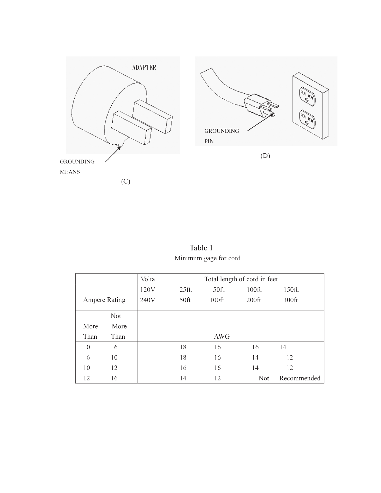
11.USE PROPER EXTENSION CORD. Make sure your extension cord is in
good condition. When using an extension cord, be sure to use one heavy
enough to carry the current your product will draw. An undersized cord will
cause a drop in line voltage resulting in loss of power and overheating. Table
1 shows the correct size to use depending on cord length and nameplate
ampere rating. If in doubt, use the next heavier gage. The smaller the gage
number, the heavier the cord.
12.WEAR PROPER APPAREL Do not wear loose clothing, gloves, neckties,
rings, bracelets, or other jewelry which may get caught in moving parts.
Nonslip footwear is recommended. Wear protective hair covering to contain
long hair.
13.ALWAYS USE SAFETY GLASSES. Also use face or dust mask if cutting
operation is dusty. Everyday eyeglasses only have impact resistant lenses,
they are NOT safety glasses.
14.SECURE WORK. Use clamps or a vise to hold work when practical. It’s safer
than using your hand and it frees both hands to operate tool.
15.DON’T OVERREACH. Keep proper footing and balance at all times.
16.MAINTAIN TOOLS WITH CARE. Keep tools sharp and clean for best and
safest performance. Follow instructions for lubricating and changing
accessories.
17.DISCONNECT TOOLS before servicing; when changing accessories, such
as blades, bits, cutters, and the like.
18.REDUCE THE RISK OF UNINTENTIONAL STARTING. Make sure switch is
in off position before plugging in.
19.USE RECONNENDED ACCESSORIES. Consult the owner’s manual for
recommended accessories. The use of improper accessories may cause risk
of injury or persons.
20.NEVER STAND ON TOOL Serious injury could occur if the tool is tipped or if
the cutting tool is unintentionally contacted.
2
11.USE PROPER EXTENSION CORD. Make sure your extension cord is in
good condition. When using an extension cord, be sure to use one heavy
enough to carry the current your product will draw. An undersized cord will
cause a drop in line voltage resulting in loss of power and overheating. Table
1 shows the correct size to use depending on cord length and nameplate
ampere rating. If in doubt, use the next heavier gage. The smaller the gage
number, the heavier the cord.
12.WEAR PROPER APPAREL Do not wear loose clothing, gloves, neckties,
rings, bracelets, or other jewelry which may get caught in moving parts.
Nonslip footwear is recommended. Wear protective hair covering to contain
long hair.
13.ALWAYS USE SAFETY GLASSES. Also use face or dust mask if cutting
operation is dusty. Everyday eyeglasses only have impact resistant lenses,
they are NOT safety glasses.
14.SECURE WORK. Use clamps or a vise to hold work when practical. It’s safer
than using your hand and it frees both hands to operate tool.
15.DON’T OVERREACH. Keep proper footing and balance at all times.
16.MAINTAIN TOOLS WITH CARE. Keep tools sharp and clean for best and
safest performance. Follow instructions for lubricating and changing
accessories.
17.DISCONNECT TOOLS before servicing; when changing accessories, such
as blades, bits, cutters, and the like.
18.REDUCE THE RISK OF UNINTENTIONAL STARTING. Make sure switch is
in off position before plugging in.
19.USE RECONNENDED ACCESSORIES. Consult the owner’s manual for
recommended accessories. The use of improper accessories may cause risk
of injury or persons.
20.NEVER STAND ON TOOL Serious injury could occur if the tool is tipped or if
the cutting tool is unintentionally contacted.

3
3
21.CHECK DAMAGED PARTS. Before further use of the tool, a guard or other
part that is damaged should be carefully checked to determine that it will
operate properly and perform its intended function-check for alignment of
moving parts, binding of moving parts, breakage of parts, mounting, and any
other conditions that may affect its operation. A guard or other part that is
damaged should be properly repaired or replaced.
22.DIRECTION OF FEED. Feed work into a blade or cutter against the direction
of rotation of the blade or cutter only.
23.NEVER LEAVE TOOL RUNNING UNATTENDED. TURN POWER OFF.
Don’t leave tool until it comes to a complete stop.
24.MAME SURE TOOL IS DISCONNECTED from power supply while motor is
being mounted, connected or reconnected.
2
11.USE PROPER EXTENSION CORD. Make sure your extension cord is in
good condition. When using an extension cord, be sure to use one heavy
enough to carry the current your product will draw. An undersized cord will
cause a drop in line voltage resulting in loss of power and overheating. Table
1 shows the correct size to use depending on cord length and nameplate
ampere rating. If in doubt, use the next heavier gage. The smaller the gage
number, the heavier the cord.
12.WEAR PROPER APPAREL Do not wear loose clothing, gloves, neckties,
rings, bracelets, or other jewelry which may get caught in moving parts.
Nonslip footwear is recommended. Wear protective hair covering to contain
long hair.
13.ALWAYS USE SAFETY GLASSES. Also use face or dust mask if cutting
operation is dusty. Everyday eyeglasses only have impact resistant lenses,
they are NOT safety glasses.
14.SECURE WORK. Use clamps or a vise to hold work when practical. It’s safer
than using your hand and it frees both hands to operate tool.
15.DON’T OVERREACH. Keep proper footing and balance at all times.
16.MAINTAIN TOOLS WITH CARE. Keep tools sharp and clean for best and
safest performance. Follow instructions for lubricating and changing
accessories.
17.DISCONNECT TOOLS before servicing; when changing accessories, such
as blades, bits, cutters, and the like.
18.REDUCE THE RISK OF UNINTENTIONAL STARTING. Make sure switch is
in off position before plugging in.
19.USE RECONNENDED ACCESSORIES. Consult the owner’s manual for
recommended accessories. The use of improper accessories may cause risk
of injury or persons.
20.NEVER STAND ON TOOL Serious injury could occur if the tool is tipped or if
the cutting tool is unintentionally contacted.

4
5
15. Make relief cuts before cutting long curves.
16. Do not cut material that is too small to be safely supported.
17. Support long heavy work from the floor.
18. Before leaving the machine, make sure the work area is clean.
19. Important: When the tool is not in use , the switch should be in the “OFF”
position and the power cord disconnected.
20. Do not remove jammed cutoff pieces until blade has stopped.
ON-OFF SWITCH PADLOCK –To safeguard the band saw from unauthorized
operation and to avoid accidental starting by children or other not qualified to use,
the use of padlock is required. To lock out the on –off switch, open the padlock,
insert through the hole of the switch on button and close the padlock. Place the
key in a location that is inaccessible to children and other not qualified to use the
tool.
SWITCH WITH KEY –The switch key must be inserted into the switch before
saw can operate. To lock the switch in the OFF position, remove the switch key
from the switch. Place the key in a location that is inaccessible to children and
others not qualified to use the tool.
4
SAVE THESE INSTRUCTIONS
ADDITIONAL SAFETY RULES FOR BAND SAWS
1. If you are not thoroughly familiar with the operation of band saws, obtain
advice from your supervisor, instructor or other qualified person.
2. Follow all wiring codes and recommended electrical connections. Make
certain that the tool is properly grounded.
3. Make all adjustments with the power “OFF”
4. Always maintain proper adjustment of blade tension, blade guides, and blade
support bearings.
5. Avoid awkward hand positions. A sudden slip could allow the hand to contact
the blade.
6. Do not attempt to saw stock that does not have a flat surface, unless a
suitable support is used.
7. Make sure blade is not contacting the workpiece before turning on the power
switch.
8. Always keep hands and fingers away from the blade when the machine is
running.
9. Hold workpiece firmly against table and feed into blade at a moderate speed.
10. Made sure that the saw blade teeth point downward toward the table.
11. Adjust upper guide to just clear work piece.
12. Disconnect machine from the power source when making repairs.
13. Replace all guards after servicing.
14. Turn off band saw if the material is to be backed out of an uncompleted cut.

5
5
15. Make relief cuts before cutting long curves.
16. Do not cut material that is too small to be safely supported.
17. Support long heavy work from the floor.
18. Before leaving the machine, make sure the work area is clean.
19. Important: When the tool is not in use , the switch should be in the “OFF”
position and the power cord disconnected.
20. Do not remove jammed cutoff pieces until blade has stopped.
ON-OFF SWITCH PADLOCK –To safeguard the band saw from unauthorized
operation and to avoid accidental starting by children or other not qualified to use,
the use of padlock is required. To lock out the on –off switch, open the padlock,
insert through the hole of the switch on button and close the padlock. Place the
key in a location that is inaccessible to children and other not qualified to use the
tool.
SWITCH WITH KEY –The switch key must be inserted into the switch before
saw can operate. To lock the switch in the OFF position, remove the switch key
from the switch. Place the key in a location that is inaccessible to children and
others not qualified to use the tool.
4
SAVE THESE INSTRUCTIONS
ADDITIONAL SAFETY RULES FOR BAND SAWS
1. If you are not thoroughly familiar with the operation of band saws, obtain
advice from your supervisor, instructor or other qualified person.
2. Follow all wiring codes and recommended electrical connections. Make
certain that the tool is properly grounded.
3. Make all adjustments with the power “OFF”
4. Always maintain proper adjustment of blade tension, blade guides, and blade
support bearings.
5. Avoid awkward hand positions. A sudden slip could allow the hand to contact
the blade.
6. Do not attempt to saw stock that does not have a flat surface, unless a
suitable support is used.
7. Make sure blade is not contacting the workpiece before turning on the power
switch.
8. Always keep hands and fingers away from the blade when the machine is
running.
9. Hold workpiece firmly against table and feed into blade at a moderate speed.
10. Made sure that the saw blade teeth point downward toward the table.
11. Adjust upper guide to just clear work piece.
12. Disconnect machine from the power source when making repairs.
13. Replace all guards after servicing.
14. Turn off band saw if the material is to be backed out of an uncompleted cut.

6
7
until a properly grounded outlet can be installed by a qualified electrician. The
green-colored rigid ear, lug, and the like, extending from the adapter must be
connected to a permanent ground such as a properly grounded outlet box.
3. Grounded, cord-connected tools intended for use on a supply circuit having a
nominal rating between 150-250 volts, inclusive:
This tool is intended for use on a circuit that has an outlet that looks like the
one illustrated in Sketch D in Figure 1. The tool has a grounding plug that
looks like the plug illustrated in Sketch D in Figure 1. Make sure the tool is
connected to an outlet having the same configuration as the plug. No adapter
is available or should be used with this tool. If the tool must be reconnected
for use on a different type of electric circuit, the reconnection should be made
by qualified service personnel; and after reconnection, the tool should comply
with all local codes and ordinances.
Note : In Canada, the use of a temporary adaptor is not
permitted by the Canadian Electrical Code.
GROUNDING
PIN
COVER OF GROUNDED
OUTLET BOX
METAL SCREW
(A)
(B)
FIGURE 1
Grounding methods
6
GROUNDING INSTRUCTIONS
1. All grounded, cord-connected tools:
In the event of a malfunction or breakdown, grounding provides a path of
least resistance for electric current to reduce the risk of electric shock. This
tool is equipped with an electric cord having an equipment-grounding
conductor and a grounding plug.
The plug must be plugged into a matching outlet that is properly installed and
grounded in accordance with all local codes and ordinances.
Do not modify the plug provided –if it will not fit the outlet, have the proper
outlet installed by a qualified electrician.
Improper connection of the equipment-grounding conductor can result In a
risk of electric shock. The conductor with insulation having an outer surface
that is green with or without yellow stripes is the equipment-grounding
conductor. If repair or replacement of the electric cord or plug is necessary, do
not connect the equipment-grounding conductor to a live terminal.
Check with a qualified electrician or service personnel if the grounding
instructions are not completely understood, or if in doubt as to whether the
tool is properly grounded.
Use only 3-wire extension cords that have 3-prong grounding plugs and
3-pole receptacles that accept the tool’s plug.
Repair or replace damaged or worn cord immediately.
2. Grounded, cord-connected tools intended for use on a supply circuit having a
nominal rating less than 150 volts:
This tool is intended for use on a circuit that has an outlet that looks like the
one illustrated in Sketch A in Figure 1. The tool has a grounding plug that
looks like the plug illustrated in Sketch A in Figure 1. A temporary adapter,
which looks like the adapter illustrated in Sketches B and C, may be used to
connect this plug to a 2-pole receptacle as shown in Sketch B if a properly
grounded outlet is not available. The temporary adapter should be used only

7
7
until a properly grounded outlet can be installed by a qualified electrician. The
green-colored rigid ear, lug, and the like, extending from the adapter must be
connected to a permanent ground such as a properly grounded outlet box.
3. Grounded, cord-connected tools intended for use on a supply circuit having a
nominal rating between 150-250 volts, inclusive:
This tool is intended for use on a circuit that has an outlet that looks like the
one illustrated in Sketch D in Figure 1. The tool has a grounding plug that
looks like the plug illustrated in Sketch D in Figure 1. Make sure the tool is
connected to an outlet having the same configuration as the plug. No adapter
is available or should be used with this tool. If the tool must be reconnected
for use on a different type of electric circuit, the reconnection should be made
by qualified service personnel; and after reconnection, the tool should comply
with all local codes and ordinances.
Note : In Canada, the use of a temporary adaptor is not
permitted by the Canadian Electrical Code.
GROUNDING
PIN
COVER OF GROUNDED
OUTLET BOX
METAL SCREW
(A)
(B)
FIGURE 1
Grounding methods
6
GROUNDING INSTRUCTIONS
1. All grounded, cord-connected tools:
In the event of a malfunction or breakdown, grounding provides a path of
least resistance for electric current to reduce the risk of electric shock. This
tool is equipped with an electric cord having an equipment-grounding
conductor and a grounding plug.
The plug must be plugged into a matching outlet that is properly installed and
grounded in accordance with all local codes and ordinances.
Do not modify the plug provided –if it will not fit the outlet, have the proper
outlet installed by a qualified electrician.
Improper connection of the equipment-grounding conductor can result In a
risk of electric shock. The conductor with insulation having an outer surface
that is green with or without yellow stripes is the equipment-grounding
conductor. If repair or replacement of the electric cord or plug is necessary, do
not connect the equipment-grounding conductor to a live terminal.
Check with a qualified electrician or service personnel if the grounding
instructions are not completely understood, or if in doubt as to whether the
tool is properly grounded.
Use only 3-wire extension cords that have 3-prong grounding plugs and
3-pole receptacles that accept the tool’s plug.
Repair or replace damaged or worn cord immediately.
2. Grounded, cord-connected tools intended for use on a supply circuit having a
nominal rating less than 150 volts:
This tool is intended for use on a circuit that has an outlet that looks like the
one illustrated in Sketch A in Figure 1. The tool has a grounding plug that
looks like the plug illustrated in Sketch A in Figure 1. A temporary adapter,
which looks like the adapter illustrated in Sketches B and C, may be used to
connect this plug to a 2-pole receptacle as shown in Sketch B if a properly
grounded outlet is not available. The temporary adapter should be used only
8
9
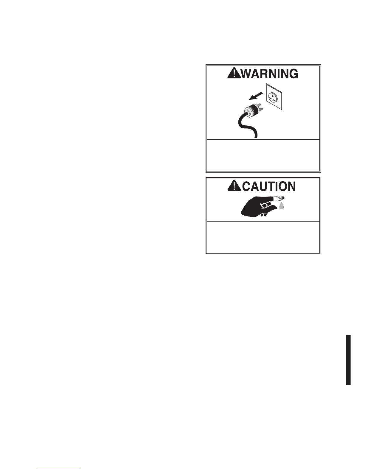
WARNING PLATES
This machine has warning symbols attached on it as shown below to ensure
proper and safe operation.
These symbols are used on the machine to indicate points or instances of
specific danger to operating personnel.
Make sure to memorize these symbols and bring them to the attention of others
as and when necessary. Do not remove safety symbols from the machine.

9
9
WARNING PLATES
This machine has warning symbols attached on it as shown below to ensure
proper and safe operation.
These symbols are used on the machine to indicate points or instances of
specific danger to operating personnel.
Make sure to memorize these symbols and bring them to the attention of others
as and when necessary. Do not remove safety symbols from the machine.

10
12
INSTALLAITON
SAFETY RULES FOR MACHINE LIFTING
1. Pay special attention to the balance of the machine while lifting.
2. Use a forklift with sufficient loading capacity to lift the machine.
3. Have another person help guide the way when lifting the machine.
4. The forks of forklift must protrude from under the machine underside.
5. The forklift must only be driven by an experienced forklift driver.
This is a heavy machine. Serious personal injury may occur if safe moving ethods are not used. To be
safe, get assistance and use power equipment to move the shipping crate and remove the machine from
the crate.
Although not required, we recommend that you mount your new machine to the floor.
Because this is an optional step and floor materials may vary, floor mounting hardware is not
included. Generally, you can either bolt your machine to the floor or mount it on machine
mounts. Both options are described below. Whichever option you choose, it is necessary to
level your machine with a precision level.
SELECTION OF LOCATION
Requirement of operating environment the operating temperature for this machine should be
between +5℃and +40℃,while the relative humidity should not exceed 50% at a maximum
temperature of +40℃.
Improper environment will affect the machine’ssafe operation, avoid the following working
area:
Avoid placing in area where the machine will rock or be uneven, thus preventing the machine
from falling or turning over. This will prevent injuries and undue wear on the machine.
Avoid placing in places where vibration may occur. Install the machine at the anticipated
place.
Whether there is any dust on the sliding surface or any defect. Clean it first to avoid setting off
sparks or causing an electrical shock.
Space allocation
Consider the largest size of workpiece that will be processed through this machine and
provide enough space around the machine for adequate operator material handing or the
installation of auxiliary equipment. With permanent installations, leave enough space around
11
FEATURES
Motor – 2HP, Single Phase 110/220 Volts.
Motor Speed –1725 RPM.
Motor Switch –Magetic control panel
Blade Speed –2300 , 3250 FPM.
Fully Balanced Cast Iron Wheels.
Table Size – 16” X 20” .
Table Material – Precision Ground Cast Iron.
Table Tilts – -5°~45°
Floor To Table Height- 36½"
Throat – 14½"
Cutting Height – 12''
Overall Height – 76”
Net Weight – 130 kg
Gross Weight – 165 kg
Packing Size- 75x58x195cm

11
12
INSTALLAITON
SAFETY RULES FOR MACHINE LIFTING
1. Pay special attention to the balance of the machine while lifting.
2. Use a forklift with sufficient loading capacity to lift the machine.
3. Have another person help guide the way when lifting the machine.
4. The forks of forklift must protrude from under the machine underside.
5. The forklift must only be driven by an experienced forklift driver.
This is a heavy machine. Serious personal injury may occur if safe moving ethods are not used. To be
safe, get assistance and use power equipment to move the shipping crate and remove the machine from
the crate.
Although not required, we recommend that you mount your new machine to the floor.
Because this is an optional step and floor materials may vary, floor mounting hardware is not
included. Generally, you can either bolt your machine to the floor or mount it on machine
mounts. Both options are described below. Whichever option you choose, it is necessary to
level your machine with a precision level.
SELECTION OF LOCATION
Requirement of operating environment the operating temperature for this machine should be
between +5℃and +40℃,while the relative humidity should not exceed 50% at a maximum
temperature of +40℃.
Improper environment will affect the machine’ssafe operation, avoid the following working
area:
Avoid placing in area where the machine will rock or be uneven, thus preventing the machine
from falling or turning over. This will prevent injuries and undue wear on the machine.
Avoid placing in places where vibration may occur. Install the machine at the anticipated
place.
Whether there is any dust on the sliding surface or any defect. Clean it first to avoid setting off
sparks or causing an electrical shock.
Space allocation
Consider the largest size of workpiece that will be processed through this machine and
provide enough space around the machine for adequate operator material handing or the
installation of auxiliary equipment. With permanent installations, leave enough space around
11
FEATURES
Motor – 2HP, Single Phase 110/220 Volts.
Motor Speed –1725 RPM.
Motor Switch –Magetic control panel
Blade Speed –2300 , 3250 FPM.
Fully Balanced Cast Iron Wheels.
Table Size – 16” X 20” .
Table Material – Precision Ground Cast Iron.
Table Tilts – -5°~45°
Floor To Table Height- 36½"
Throat – 14½"
Cutting Height – 12''
Overall Height – 76”
Net Weight – 130 kg
Gross Weight – 165 kg
Packing Size- 75x58x195cm

12
14
POWER SUPPLY REQUIREMENT
Insufficient voltage from factory power source may affect the power output of the motor and
the function of the controller.
It is important to connect this machine to the correct voltage in the factory power source.
Use only an independent power source.
3.7 CONNECT POWER SOURCE WIRES
1. Before connecting the power wires make sure the voltage between the machine and your
factory power source is the same.
2. Take out the electrical cover at the electrical control box outside.
3. Connect the power wires to the plug.
4. The machine must be properly grounded to prevent possible injury from electrical shock.
5. Connect the power wires from machine bed to the electrical control box according
connecter type.
6. Qualified electrical personnel should perform all electrical connections.
Grounding should be based on the local regulations.
13
the machine to open or remove doors/covers as required by the maintenance and service
described in this manual.
Electrical Installation
Place this machine near an existing power source. Make sure all power cords are protected
from traffic, material handling, moisture, chemicals, or other hazards. Make sure to leave
assess to a means of disconnection the power source or engaging a lockout/tagout device.
Lighting
Lighting around the machine must be adequate enough that operations can be performed
safely. Shadows, glare, or strobe effects that may distract or impede the operator must be
eliminated.
TRANSPORTATION
Carefully check over the machine whether it is damaged during transportation.
While moving the machine, be sure to note its weight distribution as well as its balance.
If the machine is damaged while being moved, please contact the manufacturer immediately.
The lifting of the machine is as easy as follows:
The machine can be lifted by a forklift.
Their forks should insert through the machine bottom.
Attention should be paid to the balance of the machine while lifting.

13
14
POWER SUPPLY REQUIREMENT
Insufficient voltage from factory power source may affect the power output of the motor and
the function of the controller.
It is important to connect this machine to the correct voltage in the factory power source.
Use only an independent power source.
3.7 CONNECT POWER SOURCE WIRES
1. Before connecting the power wires make sure the voltage between the machine and your
factory power source is the same.
2. Take out the electrical cover at the electrical control box outside.
3. Connect the power wires to the plug.
4. The machine must be properly grounded to prevent possible injury from electrical shock.
5. Connect the power wires from machine bed to the electrical control box according
connecter type.
6. Qualified electrical personnel should perform all electrical connections.
Grounding should be based on the local regulations.
13
the machine to open or remove doors/covers as required by the maintenance and service
described in this manual.
Electrical Installation
Place this machine near an existing power source. Make sure all power cords are protected
from traffic, material handling, moisture, chemicals, or other hazards. Make sure to leave
assess to a means of disconnection the power source or engaging a lockout/tagout device.
Lighting
Lighting around the machine must be adequate enough that operations can be performed
safely. Shadows, glare, or strobe effects that may distract or impede the operator must be
eliminated.
TRANSPORTATION
Carefully check over the machine whether it is damaged during transportation.
While moving the machine, be sure to note its weight distribution as well as its balance.
If the machine is damaged while being moved, please contact the manufacturer immediately.
The lifting of the machine is as easy as follows:
The machine can be lifted by a forklift.
Their forks should insert through the machine bottom.
Attention should be paid to the balance of the machine while lifting.

14
16
Tilting the table
The bandsaw table tilts up 45°
to the right or up to 10° to the
left. TO tilt the table(Fig.)
1. Loosen knob under the
table(Fig. A)&(Fig.,C).
2. Tilt table the desired angle
of degree, gauge under the
table.
3. Re-tighten knob.
C
15
TABLE ADJUSTMENT
Table assembly
1. Place table bracket on the
bandsaw so that the two bracket
pins can go into the holes on the
support.
2. Secure table bracket to
bandsaw body using the two hex
head bolt and flat washers(Fig.1)
3. Set table on bracket, insert
screw into bracket and secure with
knob
Adjusting to 90° table stop
1. Disconnect the machine from the power source.
2. Loosen the lock knobs (A) as
illustrated in (Fig.) tilt the
table towards the left until it
rests against the table stop
bolt.(Fig.,B)
3. Use a square, place on the
table against the blade. This
will allow you to verify the 90
degree to the table.
4. Turn table stop bolt to get the
90-degree angle; tighten
thelock knobs once completed. AB

15
16
Tilting the table
The bandsaw table tilts up 45°
to the right or up to 10° to the
left. TO tilt the table(Fig.)
1. Loosen knob under the
table(Fig. A)&(Fig.,C).
2. Tilt table the desired angle
of degree, gauge under the
table.
3. Re-tighten knob.
C
15
ADJUSTMENT
Table assembly
1. Place table bracket on the
bandsaw so that the two bracket
pins can go into the holes on the
support.
2. Secure table bracket to
bandsaw body using the two hex
head bolt and flat washers(Fig.1)
3. Set table on bracket, insert
screw into bracket and secure with
knob
Adjusting to 90° table stop
1. Disconnect the machine from the power source.
2. Loosen the lock knobs (A) as
illustrated in (Fig.) tilt the
table towards the left until it
rests against the table stop
bolt.(Fig.,B)
3. Use a square, place on the
table against the blade. This
will allow you to verify the 90
degree to the table.
4. Turn table stop bolt to get the
90-degree angle; tighten
thelock knobs once completed. AB

10
An adjustable table stop allows the table to easily return
to 90˚ after tilting.
To set the table stop so the table is 90˚ to the blade,
do these steps:
1. Make sure the blade is correctly tensioned as
described in the Blade Tensioning.
2. DISCONNECT BANDSAW FROM POWER!
3. Loosen the two table trunnion knobs.
4. Loosen the hex nut that locks the table stop bolt in
place.
5. Raise the upper blade guide assembly and place a 6"
machinist’s square or try-square on the table nextto
the side of the blade as illustrated inFigure 1.
Adjust the table stop bolt to raise or lower the table
until the table is 90˚ to the blade.
6. Secure the knobs and lock the table stop bolt by
tightening the hex nut against the casting. Ensure
that the bolt does not turn by holding it with anoth-
er wrench while tightening the hex nut.
Table Stop Adjustment
Blade
Table
Square
Figure 1. Squaring table to blade.
The pointer on the table tilt scale (Figure 2) must be
calibrated in order for the scale reading to be accurate.
To calibrate the pointer on the table tilt scale, do
these steps:
1. Make sure the blade is tensioned/tracking correctly
and that the table is 90˚ to the blade (this proce-
dure should be already completed with the Table
Stop Adjustment instructions).
2. Loosen the pointer screw.
3. Align the tip of the pointer with the 0˚ mark on the
table tilt scale.
4. Tighten the pointer screw.
Table Tilt Scale
Calibration
Figure 2. Table tilt scale.
Pointer
11
To ensure cutting accuracy when the table is first
installed, align the table so the miter slot is parallel to
the bandsaw blade. This procedure works best with the
largest blade that the machine accepts.
To align the miter slot parallel to the bandsaw blade,
do these steps:
1. Make sure the blade is correctly tracked and ten-
sioned.
2. DISCONNECT BANDSAW FROM POWER!
3. Loosen the trunnion bolts that secure the trunnions
to the table.
4. Place an accurate straightedge along the blade. The
straightedge should lightly touch both the front and
back of the blade (the flat part only) without touch-
ing the blade teeth.
5. Use a fine ruler to gauge the distance between the
straightedge and the miter slot. The distance you
measure should be the same at both the front and
back ends of the miter slot, as indicated by positions
"A" and "B" in Figure 3.
6. Adjust the table until the distance between the
blade and miter slot is equal at both ends.
7. Tighten the trunnion bolts.
Table Alignment
A
B
Miter Slot
Parallel
with Blade
when A = B
Straightedge
Figure 3. Checking if miter slot is
parallel to blade.
To align the fence parallel with the miter slot, do these
steps:
1. Mount the fence on the right-hand side of the blade,
at the edge of the miter slot, then lock it in place.
2. Loosen the two cap screws that mount the front rail
brackets to the table.
3. Shim between the front rail brackets and table to
make the fence parallel with the miter slot.
Tip: Shim stock works well for this, but small pieces
of paper can also work in a pinch.
4. Tighten the front rail mounting bolts.
Fence Alignment
NOTICE
Adjusting the fence parallel to the
miter slot does not guarantee straight
cuts. The miter slot may need to be
adjusted parallel to the blade. Refer to
the Table Alignment instructions.
16
13
SERVICE
When wheels are aligned, or coplanar, the bandsaw cuts
straighter, with much less vibration, heat, and blade wear
because the blade is automatically balanced on the
wheel. See Figure 5 to better understand coplanarity.
If your bandsaw develops tracking problems that can't be
fixed by adjusting the upper wheel tracking knobs, then
check the wheel alignment before taking any other steps.
Verifying Upper/Lower Wheels are Coplanar
1. DISCONNECT BANDSAW FROM POWER!
2. With the blade on and properly tensioned, hold
a straightedge or a self-made "coplanarity gauge"
(Figure 5) close to the center of both wheels. Make
sure the straightedge or gauge fully extends across
the wheels as shown in Figure 5.
—If the wheels are coplanar, the straightedge will
evenly touch the top and bottom of both wheels.
—If the wheels are not coplanar, place the straight-
edge on the lower wheel first (ensuring that it
touches both the top and bottom rim), then adjust
the upper wheel tracking knob to make the upper
wheel parallel with the lower wheel.
—If the straightedge does not touch both wheels
evenly, the upper wheel needs to be shimmed or
the lower wheel needs to be adjusted.
Shimming Upper Wheel
1. DISCONNECT BANDSAW FROM POWER!
2. Make sure the top wheel is adjusted parallel with
the bottom wheel.
3. With the straightedge touching both points of the
wheel that does not need to be adjusted, measure
the distance away from the incorrect wheel with a
fine ruler (see Figure 6).
4. Remove the blade from the saw, then remove the
wheel that needs to be shimmed.
5. Determine how many shim washers you need to com-
pensate for the distance measured in Step 3 and
place them on the wheel shaft.
6. Replace the wheel, the original washers, and the
securing nut.
Wheel Alignment
Figure 6. Measuring wheel difference.
Coplanar Parallel, Not
Coplanar
Not Parallel
Not Coplanar
Adjust
Tracking Knob
Gauge
Contacts Top
And Bottom of
Both Wheels
Coplanarity Gauge
Figure 5. Coplanar diagram.
12
Blade Changes
To replace the blade, do these steps:
1. DISCONNECT BANDSAW FROM POWER!
2. Release the tension lever.
3. Remove the table insert and the table pin. Adjust
the upper and lower guide blocks away from the
blade.
4. Open the upper and lower wheel covers and slide
the blade off both wheels.
5. Rotate the blade 90˚ and slide it through the slot in
the table.
6. Slide the new blade through the table slot, ensuring
that the teeth are pointing down toward the table.
If the teeth will not point downward in any orienta-
tion, the blade is inside-out. Put on heavy gloves,
remove the blade, and twist it rightside-out.
7. Slip the blade through the guides, and mount it over
the upper and lower wheels.
8. Apply tension.
9. Turn the tension knob until proper blade tension has
been reached according to the blade thickness
scale.
10. Check and adjust the tracking.
11. Adjust the upper/lower guide blocks and the support
bearings .
12. Close the wheel covers.
13. Replace the table insert and table pin, being sure
not to use excessive force when inserting the table
pin.
Always disconnect power to the
machine when changing blades.
Failure to do this may result in serious
personal injury.
All saw blades are dangerous and may
cause personal injury. To reduce the
risk of being injured, wear leather
gloves when handling saw blades.
17

13
When wheels are aligned, or coplanar, the bandsaw cuts
straighter, with much less vibration, heat, and blade wear
because the blade is automatically balanced on the
wheel. See Figure 5 to better understand coplanarity.
If your bandsaw develops tracking problems that can't be
fixed by adjusting the upper wheel tracking knobs, then
check the wheel alignment before taking any other steps.
Verifying Upper/Lower Wheels are Coplanar
1. DISCONNECT BANDSAW FROM POWER!
2. With the blade on and properly tensioned, hold
a straightedge or a self-made "coplanarity gauge"
(Figure 5) close to the center of both wheels. Make
sure the straightedge or gauge fully extends across
the wheels as shown in Figure 5.
— If the wheels are coplanar, the straightedge will
evenly touch the top and bottom of both wheels.
— If the wheels are not coplanar, place the straight-
edge on the lower wheel first (ensuring that it
touches both the top and bottom rim), then adjust
the upper wheel tracking knob to make the upper
wheel parallel with the lower wheel.
— If the straightedge does not touch both wheels
evenly, the upper wheel needs to be shimmed or
the lower wheel needs to be adjusted.
Shimming Upper Wheel
1. DISCONNECT BANDSAW FROM POWER!
2. Make sure the top wheel is adjusted parallel with
the bottom wheel.
3. With the straightedge touching both points of the
wheel that does not need to be adjusted, measure
the distance away from the incorrect wheel with a
fine ruler.
4. Remove the blade from the saw, then remove the
wheel that needs to be shimmed.
5. Determine how many shim washers you need to com-
pensate for the distance measured in Step 3 and
place them on the wheel shaft.
6. Replace the wheel, the original washers, and the
securing nut.
Wheel Alignment
Coplanar Parallel, Not
Coplanar
Not Parallel
Not Coplanar
Adjust
Tracking Knob
Gauge
Contacts Top
And Bottom of
Both Wheels
Coplanarity Gauge
Figure 5. Coplanar diagram.
12
Blade Changes
To replace the blade, do these steps:
1. DISCONNECT BANDSAW FROM POWER!
2. Release the tension lever.
3. Remove the table insert and the table pin. Adjust
the upper and lower guide blocks away from the
blade.
4. Open the upper and lower wheel covers and slide
the blade off both wheels.
5. Rotate the blade 90˚ and slide it through the slot in
the table.
6. Slide the new blade through the table slot, ensuring
that the teeth are pointing down toward the table.
If the teeth will not point downward in any orienta-
tion, the blade is inside-out. Put on heavy gloves,
remove the blade, and twist it rightside-out.
7. Slip the blade through the guides, and mount it over
the upper and lower wheels.
8. Apply tension.
9. Turn the tension knob until proper blade tension has
been reached according to the blade thickness scale
shown in Figure 4.
10. Check and adjust the tracking.
11. Adjust the upper/lower guide blocks and the support
bearings .
12. Close the wheel covers.
13. Replace the table insert and table pin, being sure
not to use excessive force when inserting the table
pin.
Figure 4. Tensioner adjustment.
Tension Scale
Always disconnect power to the
machinewhen changing blades.
Failureto do this may result in serious
personal injury.
All saw blades are dangerous and may
cause personalinjury.To reduce the
risk of being injured, wear leather
gloves when handling saw blades.
18
Table of contents
Other Stallion Saw manuals


