Magnum Industrial MI-91340 User manual

MODEL NO.: MI-91340
OPERATING MANUAL

IDENTIFICATION OF MAIN PARTS AND COMPONENTS
FRONT VIEW
REARVIEW
BLADE TENSION ADJUSTMENT KNOB
BLADE GUARD LOCK KNOB
UPPER BLADE GUIDE ASSEMBLY
BLADE GUARD
MITER GAUGE
TABLE ALIGNMENT PIN
DUST PORT
BASE CABINET
TABLE TILT LOCK KNOB
LOWER WHEEL COVER DOOR
ON/OFF SWITCH W/SAFETY KEY
UPPER WHEEL COVER DOOR
BLADE TRACKING ADJUSTMENT KNOB
BLADE TENSION INDICATOR
POWER CORD STORAGE BRACKETS
MOTOR PIVOT LOCKING LEVER

LIST OF CONTENTS
Once the parts have been removed from the packaging
, you should have the following items:
Carefully unpack and remove the unit and its components from its shipping container and check for missing or
damaged items as per the list of contents below.
NOTE: Please report any damaged or missing items to your GENERAL® INTERNATIONAL distributor immediately.
UNPACKING
ADDITIONAL REQUIREMENTS FOR SET UP
A
•Extra person for help with lifting
•Phillips screwdriver (regular and small)
•Flat head screwdriver
•10 mm wrench and 10 mm Hex socket
•12 mm wrench and 12 mm Hex socket
•13mm wrench and 13 mm Hex socket
•14 mm wrench and 14 mm Hex socket
•Feeler gauge set
•Combination square
N
T
U
V
W
X
Y
P
QR
S
G
D
E
F
HI
O
STAND ASSEMBLY
J
K
K
M
C
8
QTY
1WASDNAB-A
1TROPTSUD-C
4TLOBDAEHXEH-D
8REHSAWTALF-E
4TUNXEH-F
2BONKKCOL-G
H- MEDIUM HEX HEAD HEAD BOLT W/FLAT WASHER 2
1TUNXEH/WTLOBDAEHXEHGNOL-I
1EGUAGRETIM-J
1TEKCARBTLITELBAT-K
1ELBAT-L
1YEKNELLAMM3-M
61TLOBEGAIRRAC-N
61TUNEGNALF-O
8WERCSDAEHSPILLIHP-P
4TOOFGNILEVEL-Q
4TUNXEH-R
1REHSAWTALFDNATLOBXEH/WBONKROOD-S
1ETALPPOTDNATS-T
1YARTLOOTDNATS-U
1ROODDNATS-V
1LENAPRAERDNATS-W
1LENAPEDISTFELDNATS-X
1LENAPEDISTHGIRDNATS-Y

To avoid eye injury from blowing debris, wear safety goggles when blowing out
sawdust.
3. Keep the machine clean and free of sawdust. Frequently blow out or vacuum up the sawdust and wipe down
the machine occasionally with a damp rag.
Note: The wheels must always be kept clean. Dirt on the wheels will cause blade slippage.
4. Do not allow dirt, pitch or gum to build up on the ta e, guide/thrust bearings. Clean as needed with
gum and pitch remover.
Note: Do not immerse the bearings in the gum and pitch remover.
5. To prevent rust from forming on the unpainted cast iron of the table, and so that the wood slides easily while
cutting, apply a light coating of paste wax or use regular applications of any after-market surface protectant
or rust inhibitor.
REQUIRED MAINTENANCE
REPLACING THE BANDSAW BLADE
The blade should be replaced when worn out. Refer to the following symptoms to determine whether or not it is
time to replace the blade:
- It is not cutting as fast.
- It is not able to follow a cutting line as it used to.
REPLACING THE UPPER AND LOWER THRUST BEARINGS
1. Turn the tension knobAcounter-clockwise for
the blade to be loose enough to remove easily.
2. Remove the right hand side blade guard B by loosening
the two phillips head screws C, just enough
to slide it out.
3. Loosen the upper thumb screw D.
6. Use C-ring pliers G to remove the "C ring" H and
slide the bearing off the shaft I.
7. Install a new bearing on the mounting shaft
8. Re-install the C-ring.
9. Put the bearing and mounting shaft back in place,
re-install theAllen bolt and tighten the upper thumb
screw.
10. Re-install the blade-guard.
Note: After the upper thrust bearing have been changed, always
verify the lower thrust bearing. If needed, replace it proceeding
in the same way as with the upper thrust bearing.
4. Unscrew the upperAllen bolt using the supplied 3
mmAllen key E.
Note: Hold the micro adjust nut while unscrew-
ing the Allen bolt, E.
5. Remove the thrust bearing and mounting shaft F.

REMOVING / INSTALLING THE BLADE
Your bandsaw is designed to handle several blade widths ranging from 1/4” and 3/8” used for tight radius curves,
up to 1/2” and 3/4” for larger radius curves or for cutting thicker stock.
BLADE CLEARANCE
Note: When performing blade installation, removal, tensioning or tracking, maximum
clearance between the blade and both upper and lower blade guide assemblies is required to
minimize friction, which would be damaging to the blade.
Proceed as follows:
Move the upper guide blocks away from the blade:
1. Loosen the two set screwsAusing the supplied 3 mm
Allen key.
2. Pull back the 2 upper guide blocks B in their mounting
bracket C, as far away as possible from the blade.
3. Tighten the two set screwsAto lock the guide blocks in
position.
Move the upper thrust bearing back:
1. Loosen the upper thumb screw D.
2. Use the micro adjust nut E to move the thrust bearing F
back as far as possible behind the blade.
Move the lower guide blocks / thrust bearing away from the
blade:
1. Loosen the two set screws G using the supplied 3 mm
Allen key.
2. Pull back the 2 lower guide blocks H in their mounting
bracket I, as far away as possible from the blade.
3. Tighten the two set screws G to lock the guide blocks in
position.
4. Loosen the upper set screw J using the supplied 3 mm
Allen key.
5. Manually move the lower thrust bearing K back as far
as possible behind the blade.
To remove a blade:
1. Turn off the bandsaw and unplug the power cord.
2. Turn the tension knobAcounter-clockwise for
the blade to be loose enough to remove easily.
3. Remove the table alignment pin from the table slot B
and the red circular insert C from the center of the
table.
4. Remove the right hand side blade guard D by loosening
the two Phillips head screws E just enough to slide it
out

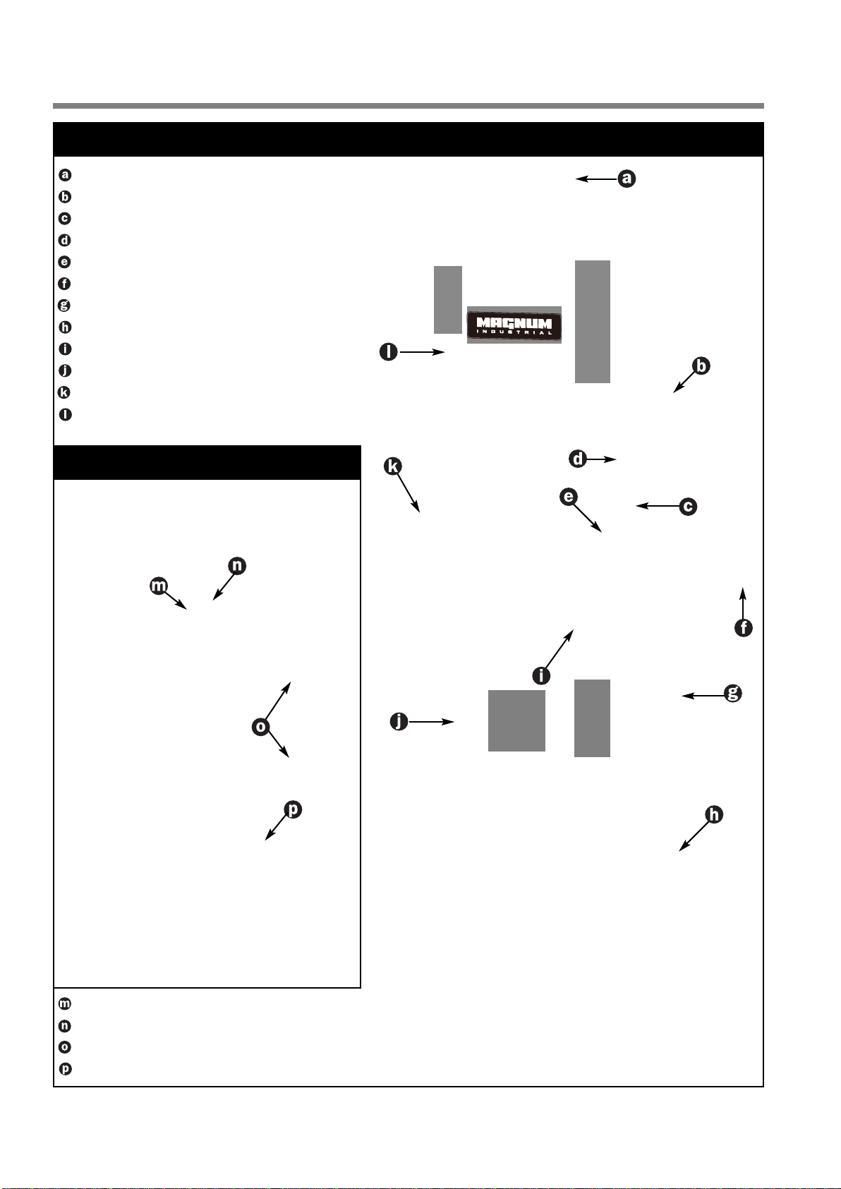
ADJUSTING THE BLADE GUARD FOR DEPTH OF CUT
The blade guard can be moved up or down to accommodate
the height of the work to be cut. To prevent the
blade (which is exible and which would not otherwise
be supported) from slipping out of position during cutting,
and to reduce risks of injuries, a minimum amount
of blade should be exposed.
The blade guard should be set 1/8” - 1/4” above
the workpiece A to prevent the blade from exing
out of position or o-line during cutting.
Adjust the height of the blade guard B to suit the thickness
of the workpiece as follows:
1. Make sure the bandsaw is turned off and the power cord is
disconnected from the power source.
2. Loosen the smaller lock knob C.
3. Move the blade guide assembly up or down D, then re-tighten
the lock knob C.
Note: The depth gauge E on the front of the blade
guard can be used as a reference but it is not
intended for high precision measurements.
ADJUSTING THE UPPER GUIDES BLOCKS AND THRUST BEARING
Note: Before adjusting the upper and lower blade guides and thrust bearings, make sure the
blade is tensioned and tracking properly. Adjust the upper and lower blade guides and thrust
bearings after each blade tension and tracking adjustment. Whenever the upper blade guide
and thrust bearing are adjusted, the lower blade guide and thrust bearing should also be
adjusted.
The blade guides blocks keep the blade from moving from side to side during cutting and must be snug but not touching the
blade in order to ensure accurate cuts. The space between each block and the blade must not exceed 0.02" (the thickness
of a sheet of paper). If less space is left, the blade will get stuck or jammed between both blocks. Too much friction will
cause blade to overheat and break. Also, the guide blocks must remain at least 1/32” behind the blade teeth to prevent
damage to the blade.
The thrust bearing keeps the blade from moving back and out of position when the work is being fed into the blade and
must be very close to the back of the blade to prevent damage to the blade during cutting.
Adjust the positioning of the upper blade guides blocks:
To avoid injury, make sure that the switch is in
the “OFF” position and that the power cord is
unplugged before performing any adjustments
on the bandsaw.
1. Loosen the two set screwsAusing the supplied 3 mm
Allen key.
2. Push the guide blocks B towards the blade.

3. Pinch a feeler gauge C between one of the guide
blocks and the blade D, and then tighten the set
screw E to set the gap between the guide block
and the blade.
4. Repeat step 3 for the other guide block on the
other side of the blade.
Adjust the positioning of the upper thrust bearing:
5. Loosen the lower thumb screw F.
6. Turn the micro lower adjust nut G to move the guide
block assembly in or out until the guide blocks are
at least 1/32” behind the blade teeth H. The guide
blocks must remain behind the blade teeth to prevent
damage to the blade.
7. Tighten the thumb screw F to lock the guide block
assembly in position.
1. Loosen the upper thumb screw J.
POSITIONING THE LOWER GUIDE BLOCKS AND THRUST BEARING
The lower blade guide blocks and thrust bearing perform the same function as the upper blade guide blocks and thrust
bearing except they do so after the blade has contacted the stock being cut.
1. Repeat steps 1 to 4 of section “Adjust the positioning of the upper blade guides blocks” with the lower blade
guide blocks.
2. Loosen the lower set screwAusing the supplied 3 mmAllen
key.
3. Manually move the guide block assembly in or out B until the
guide blocks are at least 1/32” behind the blade teeth.
4. Tighten the lower set screwAto lock the guide block
assembly in position.
5. Loosen the upper set screw C.
6. Manually move the thrust bearing D in or out until the bearing
is 1/64” behind the back edge of the blade, then tighten the
upper set screw C.
2. Turn the micro adjust nut K to move the thrust bearing
L in or out until the bearing is 1/64” behind the back edge
of the blade M, then tighten the upper thumb screw J.

CUTTING CURVES
• When cutting curves, carefully turn the workpiece so the blade follows without twisting. If the curve is so sharp that you
repeatedly back up and cut new kerf, use a narrower blade, or a blade with more set (teeth further apart).
When a blade has more set, the workpiece turns easier but the cut is rougher.
• When changing a cut, do not withdraw the workpiece from the blade. The blade may get drawn off the wheels.
• To change a cut, turn the workpiece and cut your way out through the waste material area.
• When cutting long curves, make relief cuts as you go along.
CUTTING CIRCLES
1.Adjust the blade guard assembly to 1/8" above the
workpiece.
2. Use both hands while feeding the work into the blade.
Hold the workpiece rmly against the table. Use gentle
pressure. Do not force the work.Allow the blade to cut.
3. The smallest diameter circle that can be cut is determined
by the width of the blade. For example, a 1/4"
wide blade will cut a minimum diameter of approximately
1-1/2" .
PERIODIC MAINTENANCE & LUBRICATION
Disconnect machine from power source, before performing any lubrication or maintenance.
LUBRICATION
Keep the rack and pinion A as well as the blade
tension adjustment screw B well greased and free
of dust or debris.
Clean and remove dust, debris, and old grease after
every10-15 hours of use. After cleaning, reapply
grease as needed.(Use any all purpose grease.)
The motor and all bearings are sealed and
permanently lubricated – no further lubrication is
required. No other part of this bandsaw needs
lubrication.
PERIODIC MAINTENANCE
Never operate the bandsaw with any damaged part. Replace a damaged part at the rst visible
signs of damage.
1. Inspect/test the ON/OFF switch before each use. Do not operate the bandsaw with a damaged
switch; replace a damaged switch immediately.
2. Periodically inspect the power cord/plug and the blade for damage.

ASSEMBLY INSTRUCTIONS
SERIOUS PERSONAL INJURY COULD OCCUR IF YOU CONNECT THE MACHINE TO THE
POWER SOURCE BEFORE YOU HAVE COMPLETED THE INSTALLATION AND ASSEMBLY
STEPS. DO NOT CONNECT THE MACHINE TO THE POWER SOURCE UNTIL INSTRUCTED TO
DO SO.
ASSEMBLE THE BASE CABINET
1. Thread a leveling footAwith a hex nut B on both
side panels as shown above. 2.Attach the left and right side panels to the tool
tray using 8 carriage bolts C and ange nuts D,
then tighten using a 12 mm open wrench.
3.Attach the top plate to the left and right side
panels using 4 carriage bolts C and ange nuts
D as shown above.
Note: The flanges of the top plate should fit
inside the cabinet E.
5.Attach the door knob G to the door using the
supplied hex head bolt H and lock washer I as
shown above.
6.Attach the door to the hinges on the right side
panel as shown using 4 Phillips head screws J.
Note: Hinges go behind side panel edge K.
4.Attach the rear panel to the top plate and tool
tray using 4 Phillips head screws F as shown
above.

INSTALL THE BANDSAW ONTO THE BASE
CABINET
The bandsaw mounts onto a base cabinet which provides storage
space for the miter gauge and replacementblades.
Important! Make sure all stand fasteners are rmly
tightened and that the stand cabinet is installed on
a solid, at and stable oor that is able to support
the weight of the bandsaw 191 LBS (87 kg)
The bandsaw is heavy. Do not over-exert. The help
of an assistant will be needed for the following
step.
Do not grip the bandsaw by the lower wheel cover
door when lifting. Keep hands away from blade at
all times.
1. Position the bandsaw over the four holes on top of the base
cabinet.
2. Using a 13 mm open end wrench and a 13 mm socket wrench,
secure the bandsaw to the stand as shown using the 4 hex head
bolts A, 8 at washers B and 4 hex nuts C.
Note: The hex nuts must be tightened from inside
the cabinet.
ATTACHING THE DUST PORT
The dust port A has a 2 –1/2" opening to accommodate
connection to a dust collector (not included). Install the
dust outlet on the right side of the bandsaw as follows:
1. Open the lower wheel cover door.
2. Using a 10 mm wrench, attach the dust port to the
edge of the door as shown using the hex bolts and
washers B already attached to the dust port.
ATTACHING THE TABLE-TILT BRACKET
The work table mounts on a bracket which allows
adjustment from at (0°) to any angle up to 45° to the
right. Adjustments can be made easily with the angle
scale and lock knobs.
1. Remove the two hex bolts and washers from the
lower wheel housing A.
2. Place the table-tilt bracket B on the lower wheel
housing as shown in C and align holes to the
threaded holes in the lower wheel housing (hole D
is not used).
3. Place washers on the two hex bolts E and F and
insert the bolts through the table-tilt bracket holes
and into the threaded holes in the lower wheel
housing.
4. Tighten loosely, using a 12 mm open end wrench
and 12 mm socket wrench.
5. Thread a nut onto the longer table-stop bolt D and
screw the bolt into the hole on the rear tab of the
table tilt bracket.
* Final tightening will be done after centering the
table opening with the blade.

ATTACHING THE TABLE
1. Remove the red insertAfrom the center of the
table and the table alignment pin B from the table
slot.
3. Carefully move the table into position over the
table-tilt bracket, guiding the saw blade through
the table slot D.
4. Rotate the table 1/4 turn counter-clockwise so
that the saw blade is now perpendicular to the
table slot E.
7. Make sure that the blade F is centered in the
table opening G. If the blade is not centered, slide
the table back or forward until the blade is
centered in the table opening. Then tighten the six
combination head bolts H using a 10 mm wrench
and the two hex bolts I and J using a 12 mm open
wrench and 12 mm socket wrench.
8. Re-install the red insert to the center of the table,
with the opening in the slot facing the rear of the
saw K.
9. Re-install the table alignment pin into the table
slot L.
5. Gently lower the table onto the bracket so the
long bolts C in the center of the trunnions pass
through the holes in the table-tilt bracket.
Note: If the long bolts have moved out of
position, have an assistant tap them into place
with a screw driver.
6. Thread the two lock knobs F onto the long bolts
now protruding from the underside of the tabletilt
bracket and tighten loosely.
2. Turn the table right side up. Verify that the long
bolts C in the center of each trunnion are pointing
down the holes in the table-tilt bracket.

RECOMMENDED ADJUSTMENTS
ADJUSTING THE 90º TABLE STOP AND RE-ALIGNING THE ANGLE POINTER
To ensure that your 90º cuts are square and that angled cuts are accurate with the angle indicator scale, the table
default position must be set to 90º to the blade and the angle indicator pointer must be set to read 0 when the table
is in the default (90º) position. To set the table-stop bolt:
1. Loosen the two lock knobsA. 2. Place a combination square B at on the table
with the heel of the square at against the saw
blade C.
3. Level the table until it is exactly 90° to the blade,
then tighten the lock knobsA.
4.Adjust the height of the table-stop bolt until it
touches the underside of the table D.
5. Turn the jam-nut E clockwise until it meets the
table tilt-bracket F and tighten it.
6. Loosen the lock knobs G and make sure the table
is resting on the table-stop bolt D.
7. Check the square and make sure the table is still
at 90° to the blade. If not, re-adjust the table-stop
bolt.
Never adjust the table angle while the bandsaw
is running. Turn o power rst.
1. Loosen the two lock knobs A.
2. Tilt the table until it is at the desired angle. (Refer
to the angle indicator under the bandsaw table.)
3. Tighten the lock knobs to lock the table in
position.
You will now be able to accurately return the table to the 90º position automatically without further
adjustments and scale reading for any angle other than 0 will also be accurate.
TILTING THE TABLE
The table can be tilted to any angle from 0° to 45° to the right, to allow for any type of bevel (or angle)
cutting. Refer to the table tilt angle indicator to set the angle of the table to the desired position.
8. With the table set to 90º and the stop bolt at the
correct height, make sure the table tilt angle
indicator pointer H is set to read 0º.
9. If the pointer needs to be adjusted, loosen the
screw I on the pointer of the front trunnion and
adjust the pointer H to the 0 point on the scale.
Then re-tighten the screw to secure the pointer in
place.

ADJUSTING BLADE TRACKING
Blade tracking means centering the blade on the wheelsA.
Ideally, the blade should stay relatively centered on both the
upper and lower wheels.
Due to natural variations in castings, blade thickness or density
and tire wear, absolute perfect centering alignment is
rarely attainable.Aslight misalignment of the blade on the
wheels is inevitable and as long as it is kept to a minimum
(following the steps listed below) will not hinder the performance
of the saw.
This misalignment is controlled and kept to a minimum by adjusting the tilt angle of the upper wheel.
When adjusting blade tracking to center the blade on the wheels and assuming that perfect centering is not attainable,
it is preferable to have the blade slightly off-center towards the front of the wheels rather than towards the rear
because the teeth on most bandsaw blades have alternating hook (one inner, one outer) – therefore if the blade is
centered too far back on the wheel (or if the blade tension is too tight), inner hooked teeth will dig into the wheel
tire and cause premature wear of the tire.
Nonetheless, to avoid having the blade come off of the wheels on it’s own during operation, the front edge of the
blades teeth should never be any closer than 3 mm (1/8”) from the front edge of the wheel B.
BLADE CLEARANCE
Note: As previously stated, when performing blade installation, removal, tensioning or
tracking, maximum clearance between the blade and both upper and lower bearing assemblies
is required to minimize friction, which would be damaging to the blade. Refer back and follow
the instructions for “blade clearance” before performing blade tracking adjustments.
To adjust the blade tracking:
1. Open the upper wheel cover door then rotate the wheel
slowly forward by hand. The blade should remain as
centered as possible on the wheel as it turnsA.
2. If the blade tracking must be adjusted, loosen thumb nut B,
then turn the tracking knob C, located on the rear of the
bandsaw:
a) Clockwise if the blade moves toward the front of the wheel.
This tilts the top of the wheel to the back and moves the
blade toward the center.
b) Counter-clockwise if the blade moves toward the back
edge. This tilts the top of the wheel to the front and moves
the blade toward the center.
Note: Turn the tracking knob in 1/2 turn
increments, recheck and adjust again as
needed.
3. Re-tighten thumb nut B

CHANGING SPEED SETTINGS
This model MI-91345 14" wood cutting bandsaw has 2 different speed settings; low and high.
- Low speed is to be used for cutting soft woods over 4" in height or hard woods over 2" in height.
- High speed is best for cutting soft woods under 4" in height or hard woods under 2" in height.
Note: If wood starts to burn at high speed, stop and change to the lower speed setting.
To change the speed setting:
1. Turn off power and disconnect the bandsaw from the power
source to avoid unintentional start-up of the bandsaw.
2. Open the lower wheel cover door.
3.At the back of the bandsaw, just above the motor, there is
a ratchet leverAfor loosening the tension on the drive
belt. When you pull it out, as inA, it disengages for resetting.
When you release it as in B, it engages the bolt for screwing
or unscrewing. (You can tell when it is engaged by the
orange indicater button B showing).
To loosen the drive belt, unscrew the bolt a few turns counterclockwise
then pull up on the capacitor cover of the motor C pivot the motor to
the left. This loosens the belt enough to move it between one set of
pulleys and the other.
4. To set the bandsaw speed to the slower setting; 1630 FPM
(495MPM), place the belt on the frontmost set of pulleys
as in D.
5. To set the bandsaw speed to the faster setting; 2730 FPM
(832MPM), place the belt on the rearmost set of pulleys
as in E.
6. Having repositioned the belt, push down rmly on the motor
capacitor cover to tighten the belt, then turn the ratchet
lever clockwise until it is tight and the motor does not
move.
OPERATING INSTRUCTIONS
CHECKLIST BEFORE STARTING
NOTE: Now that you have completed the four adjustment steps which are an essential part
of safe, accurate bandsaw operation, it would be a good idea to make yourself a checklist as
follows to ensure that each adjustment to the bandsaw is made in the proper order starting
with the general safety precaution:
1. Turn o the bandsaw and unplug the power cord.
2. Adjust blade tension.
3. Adjust blade tracking.
4. Adjust upper blade guides and thrust bearing.
5. Adjust lower blade guides and thrust bearing.
These additional safety measures should be be included in your checklist:
6. Make sure all the blade guards are in place.
7. Make sure the bandsaw table and work area in general are clean and free of sawdust and
debris.
These steps should always be followed when any adjustment is performed, the blade is
changed, or periodically as vibration
and normal wear and tear on the machine could throw these parts out of alignment.

REPLACING THE WHEEL TIRE
Wheel tires must be replaced if they get worn out or
damaged. (If it is worn out, the blade will not track
straight on the wheels.)
Use a at screwdriver to remove the tire from the
groove on the wheel, then install a new tire.
Note: When replacing the tires, stretch them
around the wheels but do not glue them on.
ADJUSTING/REPLACING THE LOWER WHEEL BRUSH
The lower wheel is equipped with a cleaning brush that prevents pitch and sawdust build up on the lower tire.
Any pitch and sawdust that builds up on the upper wheel tire should be removed with a stiff brush or scraped off
with a piece of wood.
Note: To avoid damaging the tire do not use a sharp knife or any kind of solvent to remove
pitch build up.
Verify that the brush keeps the lower wheel surface clean at all
times. With use and normal wear over time, the brush hairs will
soften and will not clean the surface of the wheel as well. You
then must lower the brush slightly. Proceed as follows:
1. Loosen the Phillips head screwA.
2. Slide the brush slightly down along the mounting hole
B of it’s mounting bracket, so that a fresh, stiffer part of
the hairs touches the wheel tire.
3. Tighten the screw to lock the brush in position.
REPLACING LOWER WHEEL MOTOR BELT
The lower wheel is driven by one belt mounted on either of the two pulleys powered by the motor. The belt’s tension
should be veried upon reception of the machine, then every 6 months. Slightly push on the belt with your nger.
The belt must not move more than 1/8". If the belt becomes too loose due to wear or if a breakage occurs, you
must replace it.
1. Turn off power and disconnect the bandsaw from the power source to avoid unintentional start-up.
2. Open the lower wheel cover door.
3. If needed, loosen the belt, proceeding as per step 3 in section “Changing speed settings”, on page 21.
4. Remove the belt from the groove in the pulleys and install a new one.
5. Having installed a new belt, push down rmly on the motor capacitor cover to tighten the belt, then turn the ratchet lever
clockwise until it is tight and the motor does not move.
6. Close the lower wheel cover door.

PART LIST FOR MI-91340

PART LIST FOR MI-91340
REF.NO. ITEM NO. DESCRIPTION SPECFICATION Q'TY
1 MI-91340-01 UPPER FRAME 1
2 MI-91340-02 STAR KNOB 5/16"*1-1/4" 1
3 MI-91340-03 HEX. NUT 3/16" 12
4 MI-91340-04 GUIDE POST (V TYPE) 1
5 MI-91340-05 POST SEAT Double Teeth) 1
6 MI-91340-06 THUMB SCREW M6*16L 1
7 MI-91340-07 BEARING SHAFT 2
8 MI-91340-08 BLADE GUARD 1
9 MI-91340-09 BEARING #6200ZZ 2
10 MI-91340-10 SET SCREW M6*10L 4
11 MI-91340-11 GUIDE BLOCK 4
12 MI-91340-12 ADJUSTING KNOB ASSEMBLY SK-62*M8 & 302L 1
13 MI-91340-13 LOGO PLATE 180*50 1
14 MI-91340-14 MICRO ADJUSTING NUT M6 2
15 MI-91340-15 SPRING 1
16 MI-91340-16 SLIDER 1
17 MI-91340-17 SQUARE NUT 3/8" 1
18 MI-91340-18 ADJUSTING KNOB 5/16"*2"L 1
19 MI-91340-19 UPPER WHEEL SHAFT HINGE 1
20 MI-91340-20 SPRING PIN Ø3*30L 1
21 MI-91340-21 STEEL PIN 2
22 MI-91340-22 UPPER WHEEL SHAFT 1
23 MI-91340-23 BEARING #6202ZZ 2
24 MI-91340-24 UPPER WHEEL 1
25 MI-91340-25 WHEEL PROTECTOR 2
26 MI-91340-26 HEX. NUT 1/2" 1
27 MI-91340-27 HEX. FIXTURE BOLT 3/8" 3
28 MI-91340-28 UPPER COVER INNER 1
29 MI-91340-29 UPPER DOOR 1
30 MI-91340-30 KNOB 3/8" 3
31 MI-91340-31 PIN 1/4"*16m/m 4
32 MI-91340-32 HEX. SCREW 3/4"*2-1/2" 1
33 MI-91340-33 FLAT WASHER 3/4"*46*3T 2
34 MI-91340-34 BASE 1
35 MI-91340-35 FLAT WASHER 1/4" 1
36 MI-91340-36 BLADE 93-1/2*3/8*0.65*6T 1
37 MI-91340-37 TABLE INSERT 1
38 MI-91340-38 TABLE PIN 1
39 MI-91340-39 TABLE 16"*16" 1
40 MI-91340-40 HEX. SCREW M10*50L 2
41 MI-91340-41 TRUNNION CLAMP SHOE 2
42 MI-91340-42 TRUNNION 2
43 MI-91340-43 HEX. SCREW 1/4"*5/8" 7

PART LIST FOR MI-91340
REF.NO. ITEM NO. DESCRIPTION SPECFICATION Q'TY
44 MI-91340-44 HEX. SCREW 5/16"*1-1/4'' 2
45 MI-91340-45 TRUNNION BRACKET 1
46 MI-91340-46 STAR KNOB M10 2
47 MI-91340-47 SPRING WASHER 1/4" 6
48 MI-91340-48 SCALE 1
49 MI-91340-49 HEX. SCREW 5/16"X3" 1
50 MI-91340-50 C RING S-10 2
51 MI-91340-51 PHILLIPS HEAD SCREW 3/16"*3/8" 2
52 MI-91340-52 HEX. NUT 5/16" 1
53 MI-91340-53 HEX. SCREW 1/4"*3/4" 2
54 MI-91340-54 FLAT WASHER 1/4"*16 2
55 MI-91340-55 LOWER GUIDE HOLDER 1
56 MI-91340-56 SET SCREW M6*10L 3
57 MI-91340-57 HINGE UPPER 1
58 MI-91340-58 PHILLIPS HEAD SCREW 3/16"*3/8" 2
59 MI-91340-59 PLATE 2
60 MI-91340-60 PHILLIPS HEAD SCREW /W WASHER 3/16"*3/8" 4
61 MI-91340-61 PHILLIPS HEAD SCREW M4*10L 1
62 MI-91340-62 SPRING WASHER 3/16" 16
63 MI-91340-63 PULLEY 7" Ø180 – Ø168 1
64 MI-91340-64 HEX. SCREW 5/16"*1-1/4" 4
65 MI-91340-65 C RING R34 2
66 MI-91340-66 BEARING 6204ZZ 2
67 MI-91340-67 LOWER WHEEL 1
68 MI-91340-68 SET SCREW M6*16L 2
69 MI-91340-69 LOWER DOOR 1
70 MI-91340-70 GUARD ABS 1
71 MI-91340-71 BEARING COVER 1
72 MI-91340-72 PHILLIPS HEAD SCREW 3/16"*3/8" 6
73 MI-91340-73 FLAT WASHER 5/16"*23 2
74 MI-91340-74 NAMEPLATE 1
75 MI-91340-75 GUARD STRONGER 1
76 MI-91340-76 CORD RETAINER 6N-4 2
77 MI-91340-77 POWER CORD 1
78 MI-91340-78 FLAT WASHER 5/16"*18*2T 8
79 MI-91340-79 HEX. SCREW 1/4"*1/4" 2
80 MI-91340-80 DUST CHUTE 1
81 MI-91340-81 DOUBLE ROUND KEY 5*5*30L 1
82 MI-91340-82 HEX. SCREW 1/2"*2-1/2" 1
83 MI-91340-83 FLAT WASHER 1/2"*28 1
84 MI-91340-84 MOTOR 1
85 MI-91340-85 DOUBLE ROUND KEY 5*5*60L 1
86 MI-91340-86 HEX. NUT 5/16" 4
87 MI-91340-87 SET SCREW M6*45L 2

PART LIST FOR MI-91340
REF.NO. ITEM NO. DESCRIPTION SPECFICATION Q'TY
88 MI-91340-88 MOTOR PULLEY 3" Ø50-Ø76 1
89 MI-91340-89 PHILLIPS HEAD SCREW /W WASHER 3/16"*3/8" 2
90 MI-91340-90 SAFTY SWITCH 4P HY18xx 1
91 MI-91340-91 TEETH WASHER M5 2
92 MI-91340-92 V BELT A-26 1
93 MI-91340-93 FLANGE NUT 3/8" 1
94 MI-91340-94 PHILLIPS HEAD SCREW /W WASHER 3/16"*3/8" 2
95 MI-91340-95 WARING LABEL 175*101.5 1
96 MI-91340-96 HANDEL M6*18L 1
97 MI-91340-97 FRAME COVER LOWER 1
98 MI-91340-98 FRAME COVER UPPER 1
99 MI-91340-99 WING NUT 5/16" 1
100 MI-91340-100 SPRING PIN Ø3X10L 1
101 MI-91340-101 DUST BRUSH 1
102 MI-91340-102 LOWER WHEEL SHAFT 1
103 MI-91340-103 POINTER 1
104 MI-91340-104 ANGLE SCALE 45∘1
105 MI-91340-105 LOCK NUT 1/2" 1
106 MI-91340-106 PHILLIPS HEAD SCREW /W WASHER 3/16"*1/4" 2
107 MI-91340-107 COPPER WASHER 2
108 MI-91340-108 HEX FIXTURE BOLT 2
109 MI-91340-109 FLAT WASHER 3/8"*19*2T 3
110 MI-91340-110 MITER GAUGE 1
111 MI-91340-111 Y TYPE GUIDE ACCESSORY 2
112 MI-91340-112 FLAT WASHER 3/16"*14 2
113 MI-91340-113 FLAT WASHER 1/4"*13*1.5T 6
114 MI-91340-114 SET SCREW 5/16*5/16" 1
115 MI-91340-115 SPRING 1
116 MI-91340-116 STEEL BALL 1/4" 1
117 MI-91340-117 SPRING WASHER 3/16" 3
118 MI-91340-118 BRUSH BRACKET 1
119 MI-91340-119 WARING LABEL 1
120 MI-91340-120 DOOR CLIP HEAD 3
121 MI-91340-121 PHILLIPS HEAD SCREW W/WASHER 3/16"*3/8" 1
122 MI-91340-122 FLAT WASHER 1/4"*16 2
123 MI-91340-123 BLADE GUARD LOWER 1
124 MI-91340-124 CLIP HEAD 3
125 MI-91340-125 PHILLIPS HEAD SCREW 3/16"*1/4" 3
126 MI-91340-126 ALLEN KEY 3MM 1
127 MI-91340-127 PHILLIPS HEAD SCREW /W WASHER 3/16"*3/8" 2
128 MI-91340-128 FLAT WASHER 3/16"*14 2
129 MI-91340-129 FLAT WASHER 5/16"*18 2
130 MI-91340-130 C RING S-20 1
131 MI-91340-131 PHILLIPS HEAD SCREW W/WASHER 3/16"*1/4" 12

PART LIST FOR MI-91340
REF.NO. ITEM NO. DESCRIPTION SPECFICATION Q'TY
132 MI-91340-132 C RING S-22 1
133 MI-91340-133 SPRING WASHER M5 1
134 MI-91340-134 PHILLIPS HEAD SCREW 3/16"*3/8" 1
135 MI-91340-135 HINGE LOWER 1
136 MI-91340-136 SPRING WASHER 3/4" 1
137 MI-91340-137 HEX. NUT 3/4" 1
138 MI-91340-138 FLAT WASHER 3/8"*27 1
139 MI-91340-139 HEX SCREW 3/8"*1-3/4"L 1
140 MI-91340-140 FLAT WASHER 3/8"*16 *2T 2
141 MI-91340-141 FLAT WASHER 3/8"*19 *2T 3
142 MI-91340-142 FLAT WASHER 3/8"*16 *2T 2
143 MI-91340-143 STAND 1
144 MI-91340-144 LABEL 1
Table of contents
Other Magnum Industrial Saw manuals

Magnum Industrial
Magnum Industrial MI-91500 User manual

Magnum Industrial
Magnum Industrial MI-51180 User manual

Magnum Industrial
Magnum Industrial MI-51100A User manual

Magnum Industrial
Magnum Industrial MI-91520 User manual

Magnum Industrial
Magnum Industrial MI-91400 Quick start guide

Magnum Industrial
Magnum Industrial MI-91703 User manual

Magnum Industrial
Magnum Industrial MI-93050 User manual

Magnum Industrial
Magnum Industrial MI-92300 User manual

Magnum Industrial
Magnum Industrial MI-92100 User manual

Magnum Industrial
Magnum Industrial MI-51350 User manual