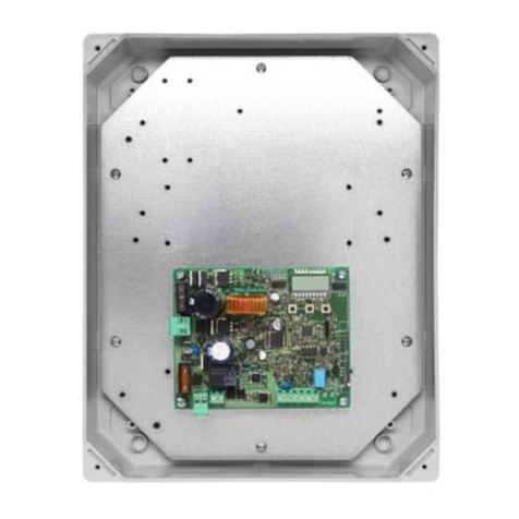
Standa 8SMC1-USBhF User manual

8SMC1-USBhF
1.5A Microstep Driver with USB Interface
User Manual
Note: Information in this manual is believed to be accurate and reliable. However no responsibility is assumed
for the consequences of its use or for any infringement of patents or other right of third parties which may
result from it use. Specifications are subject to change without notice.
Note: Windows are registered trademark of Microsoft Corporation, LabVieW and NI VISA is registered
trademark of National Instruments Inc. All other products and corporate names appearing in this manual may
or may not be registered or copyrights of their respective companies, and are used only for identification or
explanation and to the owner’s benefit, without intent to infringe.
1/14/2008 www.standa.lt Page 1 of 83

Index
1General information........................................................................................................................5
1.1 Features ...................................................................................................................................5
1.2 Description...............................................................................................................................5
1.3 Applications..............................................................................................................................6
1.4 Compatibility............................................................................................................................6
1.4.1 Connectivity .....................................................................................................................6
1.4.2 Stepper motors ...............................................................................................................6
1.5 Warranty ..................................................................................................................................6
2Functional description ....................................................................................................................7
2.1 Board overview .......................................................................................................................7
2.2 External connections ............................................................................................................10
2.2.1 Power..............................................................................................................................10
2.2.1.1 USB Powered logic mode.....................................................................................10
2.2.1.2 5V DC powered logic mode.................................................................................11
2.2.1.3 Single 7-12V DC power supply mode ................................................................11
2.2.1.4 Double power supply mode ................................................................................12
2.2.2 Stepper motor connection...........................................................................................12
2.2.3 Connection of external sensors ..................................................................................13
2.2.4 Limit switches................................................................................................................14
2.2.5 Emergency Stop switch................................................................................................15
2.2.6 Revolution sensor .........................................................................................................15
2.2.7 Encoder ..........................................................................................................................16
2.2.8 Synchronization Out .....................................................................................................18
2.2.9 Synchronization In........................................................................................................18
2.2.10 Manual control knobs...................................................................................................19
2.2.11 Local indication LEDs ...................................................................................................19
2.2.12 USB In/Out.....................................................................................................................20
3Specifications.................................................................................................................................21
3.1 Electrical.................................................................................................................................21
3.2 Motion.....................................................................................................................................21
3.3 Remote control......................................................................................................................21
3.4 Mechanical .............................................................................................................................22
3.5 Wiring diagram......................................................................................................................23
3.5.1 Wiring diagram for multi-purpose 40 pin connector ...............................................23
3.5.2 Wiring diagram for Stepper motor connector ..........................................................24
3.6 EMC.........................................................................................................................................24
4Installation .....................................................................................................................................25
4.1 Software installation.............................................................................................................25
4.1.1 SMCVieW installation....................................................................................................25
4.1.2 MicroSMC driver installation........................................................................................27
4.1.3 MicroSMC for WM installation .....................................................................................30
4.2 Hardware installation ...........................................................................................................34
4.2.1 Current sense resistors ................................................................................................34
4.3 First start on Windows XP ...................................................................................................35
4.4 First start on Windows Vista ...............................................................................................37
4.5 Switching between NI VISA and MicroSMC drivers on Windows XP ............................38
4.6 Switching between NI VISA and MicroSMC drivers on Windows Vista ........................40
1/14/2008 www.standa.lt Page 2 of 83

4.7 Known USB driver installation problems ...........................................................................44
5Application SMCVieW ...................................................................................................................46
5.1 General information..............................................................................................................46
5.2 Main screen............................................................................................................................46
5.2.1 General view..................................................................................................................46
5.2.2 Positioners and axes names........................................................................................47
5.2.3 Current and Destination positions..............................................................................47
5.2.4 Speed and precision .....................................................................................................48
5.2.5 Status and power..........................................................................................................48
5.2.6 Position slider ................................................................................................................48
5.2.7 Reset and standoff .......................................................................................................49
5.3 Main menu .............................................................................................................................49
5.4 Setup ......................................................................................................................................50
5.4.1 Buttons ...........................................................................................................................50
5.4.2 Positioner .......................................................................................................................50
5.4.3 Positioner -> Picture ....................................................................................................51
5.4.4 Positioner -> Wiring .....................................................................................................51
5.4.5 Controller identifier.......................................................................................................52
5.4.6 Power management .....................................................................................................52
5.4.7 Manual control...............................................................................................................53
5.4.8 Manual control -> Acceleration Curve.......................................................................54
5.4.9 Reset and Standoff.......................................................................................................54
5.4.10 Limit switches................................................................................................................55
5.4.11 Revolution sensor .........................................................................................................55
5.4.12 Encoder ..........................................................................................................................56
5.4.13 Synchronization.............................................................................................................57
5.4.14 Calibration......................................................................................................................58
5.4.15 Backlash compensation................................................................................................59
5.4.16 Acceleration ...................................................................................................................60
5.4.17 Safety..............................................................................................................................60
6VI’s library......................................................................................................................................62
6.1 General information..............................................................................................................62
6.1.1 Find Devices (uSMC) ....................................................................................................63
6.1.2 Initialize All Structures .................................................................................................63
6.1.3 Set Current Position (uSMC) .......................................................................................63
6.1.4 Set Mode (uSMC)..........................................................................................................63
6.1.5 Set Parameters (uSMC) ...............................................................................................63
6.1.6 Save Parameters to Flash (uSMC)..............................................................................63
6.1.7 Get Serial (uSMC) .........................................................................................................63
6.1.8 Get State (uSMC)..........................................................................................................63
6.1.9 Get Version (uSMC)......................................................................................................64
6.1.10 Start (uSMC)..................................................................................................................64
6.1.11 Stop (uSMC) ..................................................................................................................64
6.1.12 Load Profile (uSMC)......................................................................................................64
6.1.13 Update Speed Ctl (uSMC)............................................................................................64
6.2 Structures...............................................................................................................................64
6.2.1 Mode ...............................................................................................................................64
6.2.2 Parameters.....................................................................................................................65
6.2.3 State................................................................................................................................67
6.2.4 StartPlus .........................................................................................................................67
1/14/2008 www.standa.lt Page 3 of 83

6.2.5 Position...........................................................................................................................69
6.3 Examples................................................................................................................................69
7Dynamic link library USMCDLL.dll for Win2000/XP .................................................................70
7.1 New version information......................................................................................................70
7.2 General information..............................................................................................................70
7.3 File list ....................................................................................................................................70
7.4 MicroSMC.exe ........................................................................................................................71
7.5 Functions................................................................................................................................71
7.5.1 General information......................................................................................................71
7.5.2 Functions list..................................................................................................................71
7.5.3 USMC_Init ......................................................................................................................72
7.5.4 USMC_GetState.............................................................................................................72
7.5.5 USMC_SaveParametersToFlash ..................................................................................73
7.5.6 USMC_GetMode ............................................................................................................73
7.5.7 USMC_SetMode.............................................................................................................74
7.5.8 USMC_GetParameters ..................................................................................................74
7.5.9 USMC_SetParameters ..................................................................................................75
7.5.10 USMC_GetStartParameters..........................................................................................75
7.5.11 USMC_Start....................................................................................................................76
7.5.12 USMC_Stop ....................................................................................................................76
7.5.13 USMC_SetCurrentPosition ...........................................................................................77
7.5.14 USMC_GetEncoderState...............................................................................................78
7.5.15 USMC_GetLastErr..........................................................................................................78
7.5.16 USMC_Close...................................................................................................................79
7.6 Structures...............................................................................................................................79
7.6.1 USMC_Devices...............................................................................................................79
7.6.2 USMC_Parameters ........................................................................................................79
7.6.3 USMC_StartParameters................................................................................................80
7.6.4 USMC_Mode...................................................................................................................80
7.6.5 USMC_State ...................................................................................................................81
7.6.6 USMC_EncoderState.....................................................................................................81
7.7 Examples................................................................................................................................81
7.7.1 C++ example ................................................................................................................81
8Dynamic link library USMCDLL.dll for WM ................................................................................82
8.1 General information..............................................................................................................82
8.2 File list ....................................................................................................................................82
8.2.1 Host PC files...................................................................................................................82
8.2.2 Mobile device files.........................................................................................................82
8.3 Functions................................................................................................................................83
8.4 Test Applications...................................................................................................................83
8.5 Examples................................................................................................................................83
8.5.1 C++ example ................................................................................................................83
1/14/2008 www.standa.lt Page 4 of 83

1General information
1.1 Features
Electrical
Average current per phase of stepping motor up to 1.5A
Short circuit, overcurrent, overvoltage and temperature protections
Screw mounted and easy to change current sense resistors
Multi-purpose 40 pin connector for embedded applications
A number of additional connectors (15 pin D-Sub, USB type A, 2x USB type B, DC input) for
stand alone applications
Different ways of power supply, including single power, dual power and USB power (last for
8SMC1-USBhF logic only)
Motion
Resolution: full step, 1/2, 1/4,
1/8
Speed up to 5000 steps/s
Programmable speed and trip
points
Programmable accel and decel
ramps
Soft start/stop mode
Synchronization I/O
Control
Two knobs and three LEDs for
manual control and local
indication
Two programmable limit
switches and emergency stop
switch
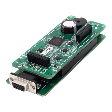
Figure 1. 8SMC1-USBhF
Quadrature encoder or
revolution sensor support
Remote control via USB 1.1
interface (up to 12 Mbps)
Embedded 3-port USB Hub, two USB ports are free for other USB device connections
Graphical user interface for Windows 2000/XP/Vista
Drivers and dynamic link library for Windows 2000/XP/Vista/Mobile host programming
Set of virtual instruments for National Instruments LabVieW
1.2 Description
The 8SMC1-USBhF controller is designed to drive one bipolar stepping motor by local
and/or remote means. Local control and indication are implemented by two knobs and three
LEDs. Remote control and monitoring are implemented via USB interface from PC. Inputs for
two limit switches, emergency switch and revolution sensor are provided.
The 8SMC1-USBhF incorporates PWM chopper type sinusoidal micro step bipolar
stepping motor driver, fully integrated mixed-signal System-on-a-Chip MCU, USB controller
1/14/2008 www.standa.lt Page 5 of 83

and 3-port USB hub on one board. Rated current for each stepping motor is set by selection
of two current sense resistors. The latter are screw mounted and easy to change. Sufficient
set of resistors is supplied with 8SMC1-USBhF. Controller features include built in over
temperature, over voltage, short circuit and reverse supply protections. There is a potential
of 40% current reduction in hold mode. In order to improve the high speed performance and
to reduce heating separate supply for logic and stepping motor can be used. Logic of 8SMC1-
USBhF can be powered by three different ways: directly from USB, from external +5V DC
power supply, from external 7-12V power supply. Emergency stop switch for unconditional
stepping motor power down is available. It may be utilized when safety is necessary. There
are two ways of communication to 8SMC1-USBhF board: by multi-purpose 40 pin connector
(convenient for embedded applications) or by a number of special additional connectors (15
pin D-Sub for stepping motor, USB type A as USB input, 2x USB type B as USB outputs, DC
input for stepper motor power supply). Embedded 3-port USB hub allows cascading of the
8SMC1-USBhF boards: it possible to connect 8SMC1-USBhF board to each of two free
downstream USB ports on another 8SMC1-USBhF board. Thus, it is possible to connect up to
30 devices per USB host controller in tree-like structure without any additional USB hubs.
The built-in powerful MCU on the 8SMC1-USBhF allows the user, via USB interface, to
control parameters such as position, acceleration/deceleration ramps, velocity, direction,
resolution, drive current, etc., to form simple or complex motions. Most of all commands are
executed on-the-fly. All parameters can be saved on PC or in MCU flash memory. The
8SMC1-USBhF has a variety of built-in functions, including local control, programmable limit
switch inputs, homing algorithm, quadrature encoder or revolution sensor support, additional
input/output for synchronization.
Thus 8SMC1-USBhF is compact, all-in-one, low cost microstep stepping motor driver
with high functionality and modern USB interface.
1.3 Applications
Controller can be used to drive any motorizes devices if their stepper motor parameters
match specifications for 8SMC1-USBhF.
1.4 Compatibility
1.4.1 Connectivity
Controller is designed to work with IBM AT compatible computer systems (with
Pentium or better processors) with Microsoft Windows 2000/XP/Vista operation systems or
mobile devices with Microsoft Windows Mobile 5.0 and higher. Only presence a USB host port
on your host device is necessary.
1.4.2 Stepper motors
Controller can operate with stepper motors according to the technical specification and
wiring requirements. Maximum allowable average phase current is 1.5A, rated voltage is 40V.
1.5 Warranty
Producer warrants the controller card 8SMC1-USBhF for the period of 1 year from the
date of sale.
1/14/2008 www.standa.lt Page 6 of 83

2Functional description
2.1 Board overview
Appearance of the 8SMC1-USBhF printed circuit board is shown on Figure 2.
Figure 2. Appearance of 8SMC1-USBhF printed circuit board
Power driver
- Sinusoidal micro step bipolar stepping motor driver. It
controls the stepper motor.
Warning: The Power driver IC fin (rear) is electrically connected to the rear of the
chip. When current flows to the fin, the Power driver IC malfunctions. If there is any
possibility of a voltage being generated between the ground of the 8SMC1-USBhF and the
fin, either ground the fin or insulate it.
Warning: There are appreciable power dissipation on Power driver (up to 6 W
depending on input voltage and rated current of stepper motor). Appropriate heatsink must
be used to maintain temperature range. Heating the Power driver over 85 oC is forbidden!
USB hub
- This chip provides one upstream port and three
downstream ports in compliance with the USB version 1.1 specification. Ports support both
full-speed and low-speed devices by automatically setting the flow rate according to the
speed of the device attached to the ports. Upstream port is wired to
USB In
and
P1
connectors and used for connections with computer or higher USB hub. One of downstream
ports is wired to
MCU
.
MCU
- Full Speed USB, 16K ISP FLASH Microcontroller. This chip
provide interface between computer and stepper motor. It keeps all current data about
stepper motor state and sends it to computer on demand.
1/14/2008 www.standa.lt Page 7 of 83

USB Out
- Two USB type A connectors are placed on the rear of
8SMC1-USBhF printed circuit board. It allows the connection of other USB devices or lower
USB hubs.
JP1
- Enable/Disable Emergency stop switch jumper, see Figure
3
and Figure 4.
Figure 3. Emergency stop switch Enabled Figure 4. Emergency stop switch Disabled
USB In
- USB type B connector is placed on the front of 8SMC1-
USBhF printed circuit board. It is used for connections with computer or higher USB hub.
Stepper motor connector
- This 15 pin D-Sub (female) connector is used for
connection of 8SMC1-USBhF device to stepper motor. All additional wiring (limit switches,
emergency limit switch, revolution sensor and corresponding power supply) is included in this
connector too. Dimensions of stepper motor connector see on Figure 5. For more information
see 2.2.2.
Figure 5. Stepper motor connector: dimensions and pinout
Current sense resistors
- Pair of current sense resistors is necessary to keep correct
rated current on windings of stepper motor. Resistors are screw mounted and easy to
change. Sufficient set of resistors is supplied with 8SMC1-USBhF.
Warning: Current sense resistors must be chosen for every stepper motor according to
its rated current and connection diagram. For more details see 4.2.1. of User Manual. Wrong
current sense resistors can cause the malfunction of 8SMC1-USBhF or damage stepper
motor.
Voltage regulator
- It is used for supply board logic when external 7-12V
power supply for logic is used (for more details see 2.2.1).
Warning: There is some power dissipation on Voltage regulator (up to 0.5 W
depending on input voltage). Appropriate heatsink may be required. Heating the Voltage
regulator over 85 oC is forbidden!
JP2
- Board logic power supply jumper. A way of logic power
supply is determined by this jumper. There are three different ways: directly from USB (as
1/14/2008 www.standa.lt Page 8 of 83

shown on Figure 6), from external +5V stabilized DC power supply (as shown on Figure 7),
from external 7-12V unstabilized DC power supply (as shown on Figure 8).
Figure 6. USB
powered board logic
Figure 7. Board logic powered
by 5V DC power supply
Figure 8. Board logic powered
by 7-12V power supply
Note: If you want to change the power logic jumper position make the following steps:
Turn the power of 8SMC1-USBhF board OFF, unplug the USB In connector, change the JP2
position, turn the power of 8SMC1-USBhF board ON and plug USB In connector back.
Don’t change the JP2 position when USB cable is plugged because it can entail
some mistakes in USB root hub operation.
Connector P1
- Multi-purpose 40 pin connector. All other connectors (USB
In, USB Out, Stepper motor connector and Power In) are duplicated here. This connector is
designed for embedded applications. Only one standard ribbon cable required for all
connections by P1. Connector P1 Pin assignment is shown on Figure 9. Dimensions are
shown on Figure 10.
Figure 9. Connector P1. Pinout
Figure 10. Connector P1. Dimensions.
Note: Some specific contacts (LEDs and knobs for manual control, for example) are only
on connector P1.
Power In
- Low-voltage power socket. 7-40V power input for stepper
motor only or 7-12V power input for stepper motor and board logic. Operating mode is
determined by JP2 and Connector P1.
1/14/2008 www.standa.lt Page 9 of 83

Figure 11. Power In connector. Dimensions. Figure 12. Power In connector. Pinout.
Dimensions are shown on Figure 11. Contacts appointment is shown on Figure 12.
Outside contact has 6,3 mm diameter. It is Ground. Central contact has a 2,0 mm diameter.
It is a positive contact for 7-40V stabilized DC power supply connection.
2.2 External connections
2.2.1 Power
8SMC1-USBhF board allows several different ways of power supply connections. They are
shown on Table 1.
Stepper motor supply
Powered by 7-12V DC Powered by 7-40V DC
USB Powered logic modeUSB powered , for details see 2.2.1.1
5V DC powered logic modePowered by 5V DC , for details see 2.2.1.2
Logic
supply Single 7-12V DC power
supply mode, for details
see
Double power supply
mode, for details seePowered by 7-12V DC
2.2.1.3 2.2.1.4
Table 1. 8SMC1-USBhF power supply modes
Warning: 8SMC1-USBhF power supply must never exceed 40V. Power driver can be
damaged if such exceeding happened.
Note: Exact current consumption from external 7-40V DC power supply for stepper motor
supplying purposes depends on stepper motor rated current and voltage. It is recommended
that rated current and voltage loading of this DC power supply exceed the stepper motor
rated current and voltage. It is true for all ways of power supply connection.
Let’s examine this table more accurately.
2.2.1.1 USB Powered logic mode
In this case logic of 8SMC1-USBhF board is powered by USB; stepper motor is powered
by external 7-40V stabilized DC power supply. Connection diagram for Power In is shown on
Figure 12, for multi-purpose 40 pin connector P1 on Figure 13. Correct position of board logic
power supply jumper (JP2) is shown on Figure 6.
1/14/2008 www.standa.lt Page 10 of 83

Figure 13. Connection of 7-40V stabilized DC power supply to P2 connector
Note: In this mode 8SMC1-USBhF requires 80 mA from USB. Make sure that feeding USB
hub can provide this current.
Note: Almost all active USB hubs (include USB root hubs) provide 500 mA power supply
that is sufficient for five 8SMC1-USBhF devices.
2.2.1.2 5V DC powered logic mode
In this case logic of 8SMC1-USBhF board is powered by external stabilized +5V DC
power supply; stepper motor is powered by external 7-40V stabilized DC power supply.
Correct position of board logic power supply jumper (JP2) is shown on Figure 7. Connection
diagram for multi-purpose 40 pin connector P1 is shown on Figure 14.
Figure 14. Power supply connection to P2 connector in +5V DC powered logic mode
Note: In this mode 8SMC1-USBhF requires 80 mA from external stabilized +5V DC power
supply. Make sure that external stabilized +5V DC power supply can provide this current.
2.2.1.3 Single 7-12V DC power supply mode
In this case logic of 8SMC1-USBhF board and stepper motor is powered by single 7-12V
DC power supply. Correct position of board logic power supply jumper (JP2) is shown on
Figure 8. Connection diagram for powering through multi-purpose 40 pin connector P1 is
shown on Figure 15. Connection diagram for powering through Power In connector is shown
on Figure 12. In the last case pins 1 and 3 of multi-purpose 40 pin connector P1 must be
connected together by jumper or other way as shown on Figure 16.
1/14/2008 www.standa.lt Page 11 of 83

Figure 15. Power supply connection to P2 connector in single 7-12V DC power supply mode
Figure 16. Pin 1 and 3 connection in single 7-12V DC power supply mode
Warning: If a single power supply mode is used, make sure that input voltage is not
exceeding 12V. Otherwise the overheating of the Voltage regulator may happen. Heating the
Voltage regulator over 85 oC is forbidden!
2.2.1.4 Double power supply mode
In this case logic of 8SMC1-USBhF board is powered by external 7-12V DC power
supply; stepper motor is powered by external 7-40V stabilized DC power supply. Correct
position of board logic power supply jumper (JP2) is shown on Figure 8. Connection diagram
for multi-purpose 40 pin connector P1 is shown on Figure 17.
Figure 17. Power supply connection to P2 connector in double power supply mode
2.2.2 Stepper motor connection
There are two ways of stepper motor connections: by Stepper Motor Connector (see
Figure 19) or by multi-purpose 40 pin connector P1 (see Figure 18).
Figure 18. Stepper Motor Connection to multi-purpose 40 pin connector P1
1/14/2008 www.standa.lt Page 12 of 83

Figure 19. Stepper Motor Connection to Stepper Motor Connector
Warning: Make sure that there are no contact between stepping motor phase windings
and 8SMC1-USBhF ground. Power driver will be damaged obligatory if such grounding
present.
Warning: You must never connect to, or disconnect from the 8SMC1-USBhF any
stepping motors while the controller keeps currents in the motor windings. Power driver can
be damaged if such reconnection happened.
2.2.3 Connection of external sensors
All external sensors (limit switches, emergency limit switch, revolution sensor and knobs)
are connected to 8SMC1-USBhF by the same way. There are several different possibilities of
connection for every sensor. Farther we examine these possibilities more accurately.
Electrically external sensors may be a dry contact type or phototransistor based. All
inputs have an internal weak pull up to 3.3V. Open circuit correspond to high level on input,
closed to ground circuit correspond to low level on input. Controller inputs are marked on
Figure 20, Figure 21, Figure 22, Figure 23 and Figure 24 as XX.
Note: Be careful with optocouples. Makes sure that voltage drop on phototransistor
exceed 2.5V in off state and do not exceed 0.5V in on state. It is important for correct work
of 8SMC1-USBhF input 3.3V logic.
The pattern of phototransistor based external sensor connection to multi-purpose 40
pin connector P1 is shown on Figure 20, to Stepper motor connector - on Figure 21. One
optocouple can be connected to Stepper motor connector by simple way that illustrated on
Figure 22. No external current-limiting resistors are required. Revolution sensor (see 2.2.6)
is connected by this way usually. The pattern of dry contact type external sensor
connection to multi-purpose 40 pin connector P1 is shown on Figure 23, to Stepper motor
connector is shown on Figure 24.
1/14/2008 www.standa.lt Page 13 of 83

Figure 20. Pattern of optocouple connection to multi-purpose 40 pin connector P1
Figure 21. Pattern of optocouple connection to Stepper motor connector (Method 1)
Figure 22. Pattern of optocouple connection to Stepper motor connector (Method 2)
Figure 23. Pattern of dry contact connection to multi-purpose 40 pin connector P1
Figure 24. Pattern of dry contact connection to Stepper motor connector
2.2.4 Limit switches
Two limit switches can be used: Limit switch 1 and Limit switch 2. These contacts are
used for determination of limits in translational stages, for determination a null position in
rotational stages, etc. It can be programmed as normally opened or closed contact. It can be
enabled or disabled by software (see 5.4.10). Also it is possible to swap limit switches by the
software. Limit switches are connected to 8SMC1-USBhF according to 2.2.3. Controller inputs
for each limit switch are shown on Table 2.
1/14/2008 www.standa.lt Page 14 of 83

Pin number on
External sensor Stepper motor connector Multi-purpose 40 pin connector P1
Limit switch 1 9 20
Limit switch 2 8 17
Table 2. Connection of Limit switches
2.2.5 Emergency Stop switch
Emergency stop switch is used for unconditional stepping motor power down. It can stop
stepper motor forcedly if it is impossible to do by software in consequence of program error.
This sensor is connected directly to power down circuit of Power driver. Emergency stop
switch must be a dry break contact. There is no possibility to control this switch by software,
only monitoring is possible. If Emergency stop switch is not used, set emergency stop jumper
in Off position (see Figure 4), otherwise in On position (see Figure 3).
Note: If Emergency stop switch is not used but emergency stop jumper set in On position
then stepper motor will be de-energized and Ext. off indicator will lighting up (see. 5.2.5).
For correct working set the jumper in Off position (see Figure 4).
Connection diagram to multi-purpose 40 pin connector P1 is shown on Figure 25, to
Stepper motor connector is shown on Figure 26.
Figure 25. Connection Emergency Stop switch to multi-purpose 40 pin connector P1
Figure 26. Connection Emergency Stop switch to Stepper motor connector
2.2.6 Revolution sensor
Revolution sensor is intended for stepper motor stall detection. 8SMC1-USBhF can
receive data about the real position of stepper motor shaft from Revolution sensor. Latter is
an external sensor (see 2.2.3) that joins directly to stepper motor shaft and change electrical
state several times per stepper motor shaft revolution.
Usually Revolution sensor is a small disk with narrow axial slit. Disk mounts directly on
stepper motor shaft. Optocouple is used as an external sensor. Optocouple’s emitter and
detector are set near the slit of the disk, by different sides. When slit is positioned on emitter
and detector optocouple is opened (optocouple output signal is low). If slit closes emitter
from detector optocouple is closed (optocouple output signal is high).
Examine how the Revolution sensor works more accurately by the example of SMCVieW
application (see chapter 5). When Revolution sensor is enabled and stepper motor is moving,
controller counts tics (one full step is equal to 64 tics) which it gives to stepper motor and
compare this number of pulses with the value Tics per revolution (see 5.4.11). If the
difference is greater than ErrorVal, Revolution sensor error flag is setting up, indicator RT
1/14/2008 www.standa.lt Page 15 of 83

error is lighting up (see 5.2.5) and stepper motor stops if Stop driver if error is detected
checkbox is marked or continue moving in other way. If Revolution sensor error flag is
setting up, it remains up until it will be reset by Reset error status button.
When revolution sensor is enabled error value is accumulated for all movements that
happened (for right direction and left direction separately) and Revolution sensor error flag
will be set if accumulated error value exceeds ErrorVal. It provides accuracy about
ErrorVal/64 steps for all movements when revolution sensor is enabled. Configuration of
Revolution sensor is possible by software (for example, see 5.4.11).
Controller inputs for Revolution sensor is shown on Table 3.
Pin number on
External sensor Stepper motor connector Multi-purpose 40 pin connector P1
Revolution sensor 12 18
Table 3. Connection of Revolution sensor
2.2.7 Encoder
Encoder is a sensor of mechanical motion. Quadrature encoder is intended for direct
measurement of stepper motor shaft position. It translates shaft angle into two shifted
electrical signal on CH A and CH B outputs (see Figure 27). Mechanical action of optical
quadrature encoder is illustrated on Figure 28. Two optocouples are used. Emitter and
detector are set near the disk, by different sides. When slit is positioned on emitter and
detector then optocouple is opened (optocouple output signal is low). If slit closes emitter
from detector then optocouple is closed (optocouple output signal is high). Optocouple
signals usually are shifted by half of encoder cycle (see Figure 27).
The main characteristic of quadrature encoder is a number of cycles per revolution
(CPR). Most common encoders have 100-1000 CPR. Each cycle can be decoded into 1, 2 or 4
codes, referred to as X1, X2 or X4 resolution multiplication. This controller used X2 resolution
multiplication.
Connection diagram of encoder to multi-purpose 40 pin connector P1 is shown on Figure
30, to Stepper motor connector is shown on Figure 29.
Figure 27. Electrical signal on CH A and CH B outputs of quadrature encoder
1/14/2008 www.standa.lt Page 16 of 83

Figure 28. Optical quadrature encoder mechanical alignment
Figure 29. Encoder connection to Stepper motor connector
Figure 30. Encoder connection to multi-purpose 40 pin connector P1
Note: Encoder share one input on board with revolution sensor and one input with
synchronization in. Therefore makes sure that revolution sensor and synchronization input
are disconnected from corresponding devices before using the quadrature encoder.
Note: Usually encoder module outputs are open collector with internal pull-up resistors.
When driving a cable, they will provide good high-to-low transition times. But low-to-high
times will stretch out in proportion to the cable length and capacitance. If a cable driver is
not used, you can add a pull-up resistor R=1-5K Ohm (see Figure 29, Figure 30) to +5 Volts
on each output to improve these rise times.
Note: For correct work of encoder at high speed it is necessary to use special version of
8SMC1-USBhF controller board. Ask this option your local dealer.
1/14/2008 www.standa.lt Page 17 of 83

2.2.8 Synchronization Out
8SMC1-USBhF can serve as an external synchronization for other devices. It can produce
TTL output pulse every Nsteps, where Nis controlled by software. It is usually used for
starting some repeated action like a routine measurement.
Synchronization output sends a TTL signal. Maximum output high level current is 5 mA.
Active state is high. Duration is programmable (see 5.4.13).
Connection diagram to multi-purpose 40 pin connector P1 is shown on Figure 31, to
Stepper motor connector is shown on Figure 32.
Figure 31. Synchronization output on multi-purpose 40 pin connector P1
Figure 32. Synchronization output on Stepper motor connector
Note: It is possible to use synchronization output as general purpose digital output. Use
USMC_SetMode() function (see Chapter 0) or Set Mode (uSMC) VI (see Chapter 6), or
SMCVieW application (see Chapter 5) for control it.
2.2.9 Synchronization In
8SMC1-USBhF can work in pulse triggering mode. In this case controller waits
synchronization pulse then executes predefined movement. 8SMC1-USBhF can shift stepper
motor by predefined number of steps only after first synchronization pulse or on every
synchronization pulse. It is usually used for starting predefined movement after each
measurement by synchronization pulse from measuring instrument. Wide range of devices
may use as a synchronization pulse generator. For example, synchronization outputs of other
8SMC1-USBhF may be used as a synchronization pulse generator.
Synchronization input receives TTL signal. Required input current is 1 mA. Active state is
high.
Connection diagram to multi-purpose 40 pin connector P1 is shown on Figure 33, to
Stepper motor connector is shown on Figure 34.
Note: When synchronization input mode enabled, press Start button in SMCVieW (see
5.2.3) or execute Set Mode (uSMC).vi in VI’s library (see 6.1.4), or run USMC_Start in
USMCDLL.dll (see 7.5.11). Then controller starts waiting input synchronization pulse.
Figure 33. Synchronization input on multi-purpose 40 pin connector P1
1/14/2008 www.standa.lt Page 18 of 83

Figure 34. Synchronization input of Stepper motor connector
2.2.10 Manual control knobs
Manual control is possible on 8SMC1-USBhF. There are inputs for two knobs: "Up” and
“Down”. Knob "Up” is intended for moving positioner "Up” (step counter in 8SMC1-USBhF is
incremented), Knob "Down” is intended for moving positioner "Down” (step counter in
8SMC1-USBhF is decremented).
Knobs are usually used for manual precise positioning of stage, for example in
calibrating. Another common application of knobs – control of stepper motors without
computer.
When knob is pushed positioner makes one step (or microstep, depends on current
resolution). If knob stays pushed during Tbto1 (see 5.4.8 for more information) stepper motor
starts rotation with Vbp1 speed. If knob stays pushed during Tbto1+Tbto2 stepper motor
increases speed up to Vbp2. If knob stays pushed during Tbto1+Tbto2+Tbto3 stepper motor
increases speed up to Vbp3. If knob stays pushed during Tbto1+Tbto2+Tbto3+Tbto4 stepper
motor increases speed up to Vbp4. If knob is released stepper motor stops rotation
immediately.
If two knobs are pushed and held during Reset timeout (see 5.4.8) then 8SMC1-
USBhF resets and shifts to null position (in ticks).
All speeds and timeouts are programmable.
Knobs are connected to 8SMC1-USBhF according to 2.2.3. Controller inputs for each
knob are shown on Table 4.
Pin number on
External sensor Stepper motor connector Multi-purpose 40 pin connector P1
Knob Up - 15
Knob Down - 16
Table 4. Connection of knobs
2.2.11 Local indication LEDs
Local indication is possible on 8SMC1-USBhF. There are outputs for three LEDs: "Up”,
“Down” and “Status”. LED "Up” blinks when stepper motor is moving "Up” (step counter in
8SMC1-USBhF is incremented) and light if Limit switch 1 is reached (or Limit switch 2, if
Swap Limit switches option is enabled). LED "Down” blinks when stepper motor is moving
"Down” (step counter in 8SMC1-USBhF is decremented) and light if Limit switch 2 is reached
(or Limit switch 1, if Swap Limit switches option is enabled). For more information about
Limit switches see 2.2.4. LED "Status” blinks when 8SMC1-USBhF is powered and works
properly but USB connection to 8SMC1-USBhF software driver on computer is unavailable.
LED "Status” light when 8SMC1-USBhF works properly and USB connection to 8SMC1-USBhF
software driver is established.
1/14/2008 www.standa.lt Page 19 of 83

Output current for LED is limited by 10 mA. Any LEDs with rated current 5-10 mA may
be used for local indication. LEDs wiring on Multi-purpose 40 pin connector P1 is shown on
Figure 35.
Figure 35. LED wiring on Multi-purpose 40 pin connector P1
2.2.12 USB In/Out
There are two ways of communication to 8SMC1-USBhF board: by multi-purpose 40 pin
connector (convenient for embedded applications) or by special USB In and USB Out
connectors (see 2.1).
USB In (USB type B connector) is used for connection with computer or higher USB
hub. Embedded 3-port USB hub allows cascading of the 8SMC1-USBhF boards. USB Out (two
USB type A connectors) allow the connection of other USB devices or lower USB hubs to this
8SMC1-USBhF board.
Caution: Use only operable USB cables! Defective USB cable may be a cause of 8SMC1-
USBhF malfunction.
USB pins on multi-purpose 40 pin connector may be useful for embedded multi-axis
applications. No bulky USB connectors are necessary. Only one ribbon cable is used.
Pinout of USB ports on multi-purpose 40 pin connector P1is shown on Table 5.
Pin number on Multi-purpose 40 pin connector P1
Pin description USB In USB Out 1 USB Out 2
D+ 37 33 29
D- 38 34 30
GND 39 35 31
+5V 40 36 32
Table 5. USB ports pinout on Multi-purpose 40 pin connector P1
1/14/2008 www.standa.lt Page 20 of 83
Other manuals for 8SMC1-USBhF
1
Table of contents
Other Standa Controllers manuals
Popular Controllers manuals by other brands

LEGRAND
LEGRAND Wattstopper LMJA-8125-SM installation instructions
IAI
IAI ROBO Cylinder RCS4-TA4C instruction manual
Kramer
Kramer FC-28 user manual
Leviton
Leviton miniZ mZb00-102 user guide

Precision Digital Corporation
Precision Digital Corporation ProtEX-MAX PD8-6210 instruction manual
Grozone Control
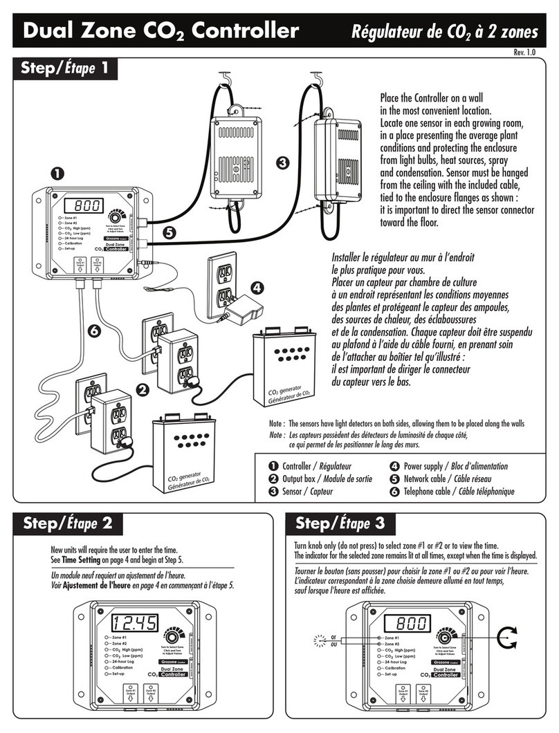
Grozone Control Dual Zone CO2 Controller manual
