manuals.online logo
Brands
  1. Home
  2. •
  3. Brands
  4. •
  5. Standard Horizon
  6. •
  7. Microphone
  8. •
  9. Standard Horizon RAM4 User manual

Standard Horizon RAM4 User manual

Front and Rear Panel
①Power/VOL knob
Press and hold this knob to turn the transceiver and the remote mic ON or OFF.
Adjusts the speaker volume level.
②DIAL/ENT knob
While the normal screen is displayed, rotate the DIAL/ENT knob to select your desired channel. While the MENU
screen is displayed, rotate the knob to select your desired menu item.
②①
③
④
⑤
⑥
⑦
⑧
⑨
⑩
⑪
⑫
⑦
⑬
⑭
⑮
⑯
SSM-70H
Remote Station Microphone RAM4
The RAM4 (SSM-70H)allows you to remotely control all functions of the enabled Standard Horizon
xed mount VHF radio. The full dot matrix display and programmable keys make operation simple and
fast. Additional features include turning the radio ON/OFF and all DSC functions including Distress.
The RAM4 (SSM-70H) can be extended up to 70 feet using the optional CT-100 (23 feet) extension
cable. The RAM4 (SSM-70H) is backed by an industry leading 3-years waterproof warranty.
Owner’s Manual
The details of the installation and operation of the RAM4 (SSM-70H)is included in the owner’s
manual of the compatible xed mount radio, or it can be downloaded at www.standardhorizon.com.
Secondary uSe
Press this knob to enter a selection in the MENU.
③SQL key (Squelch control)
Press this key to activate the squelch adjustment mode. Press the CH▲ or CH▼ key to adjust the squelch level.
④PTT (Push-To-Talk)switch
Push this switch to enable the transmitter.
⑤CLEAR/ key
Press this key to cancel a menu selection. Press and hold this key to activate the key lock function.
Press and hold this key again to deactivate the key lock function.
⑥Microphone
The internal microphone transmits your voice reducing background noise using Clear Voice Noise Reduction
Technology.
Note: Position your mouth about 1/2” (1.5 cm)away from the microphone hole and speak in a normal voice.
⑦◄/►key
Press these keys to switch the function of soft keys.
Secondary uSe
While the MENU screen is displayed, press the key to slide the on-screen menu to the right/left side.
⑧MENU key
Press this key to access the MENU.
⑨CH▼/CH▲ key
These keys are used to change the operating channel.
Press the key momentarily, the channel increases/decreases one step. Holding the key, the channel increases/
decreases continuously.
Secondary uSe
While the MENU screen is displayed, press the key to slide the on-screen menu upward/downward.
⑩ Display
Full dot matrix display, 222 by 162 pixels.
⑪Soft keys
These three programmable keys can be customized in the setup menu to quickly access advanced functions of the radio.
⑫ Strobe LED
When the [STROBE] soft key is pressed, the Strobe LED will light or ash repeatedly.
From MENU → SETUP → CONFIGURATION → STROBE LED, you can select one option from “CONTINUOUS”,
“SOS”, “BLINK 1”, “BLINK 2” and “BLINK 3”.
⑬16/S key
Pressing this key immediately recalls channel 16 from any channel location. Holding down this key recalls the SUB
channel (The default setting is channel 9). Pressing this key again reverts to the previous selected working channel.
⑭Speaker
The internal speaker is located here.
⑮DATA jack
Use the micro USB type B jack for RAM4 (SSM-70H) rmware updates.
Note: When the DATA jack is securely covered with rubber cap, the SSM-70H meets the waterproong performance.
⑯DISTRESS key
This key is used to send a DSC distress call.
Included Accessories and replacement part numbers
(1) 23 Feet Routing Cable (S8101512)
(2) Rubber Cap (RA052520A)
(3) Mounting Bracket (RA052510A)& Screws (U24312020 x 4 pcs)
(4) Microphone Hanger (RA0458800)& Screws (U40412220 x 2 pcs)
(5) Ferrite Cores (L9190212 x 2 pcs)
(6) Operating Manual
(1)
(2)
(3) (4) (5)
Safety Precautions (Be Sure to Read)
Be sure to read the safety precautions of Operating Manual of the compatible transceiver to use
this product safely.
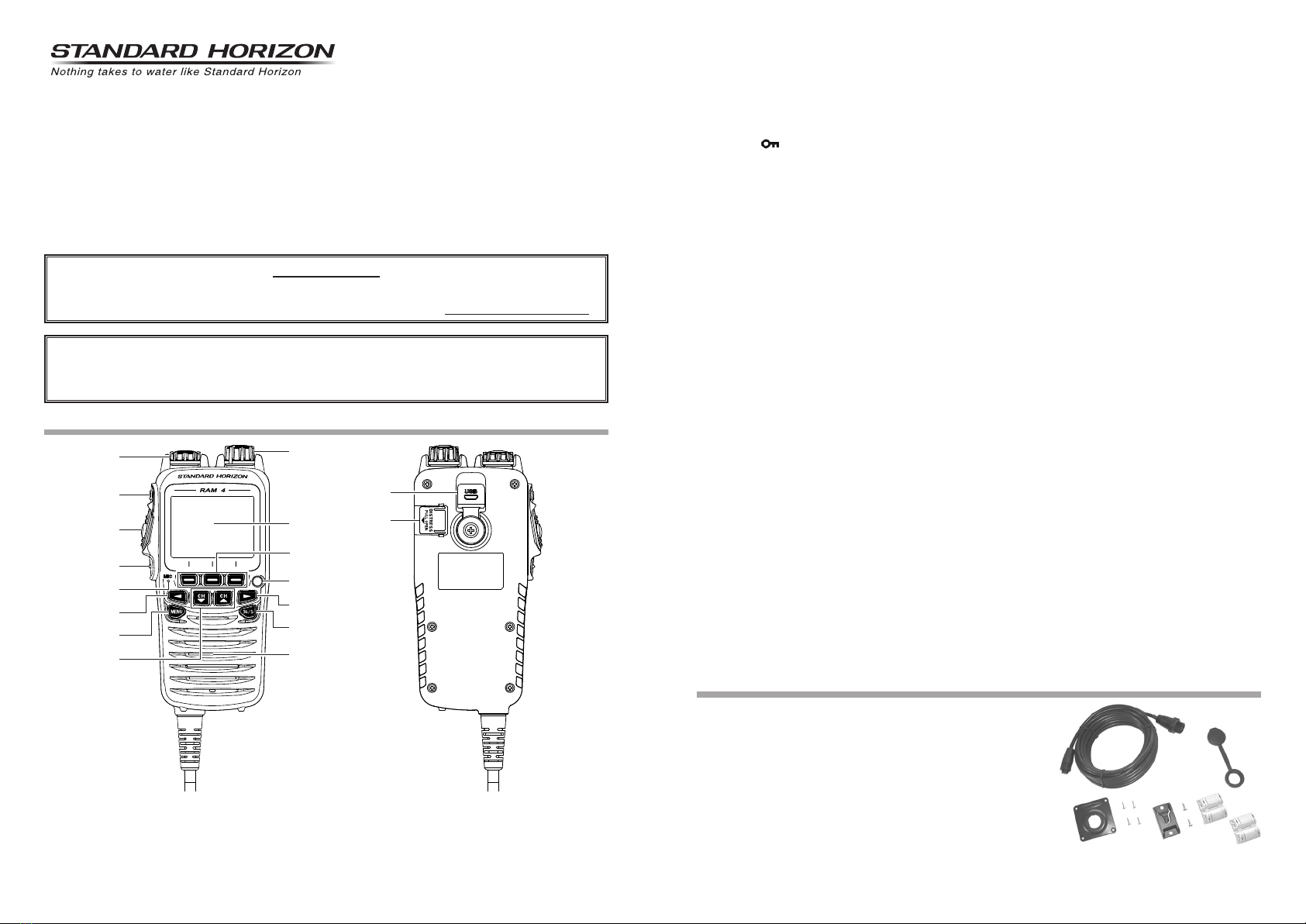
Optional Accessories
(1) CT-100 23 Feet Extension Cable
(2) MLS-300 External Loud Speaker
(3) MLS-310 10W Amplied External Speaker
Conguration Setup
SSM-70H operation is same as the enabled radio. This makes operation of the radio and SSM-70H
microphone similar and much easier. The only difference is that the following two items are added to
CONFIGURATION SETUP:
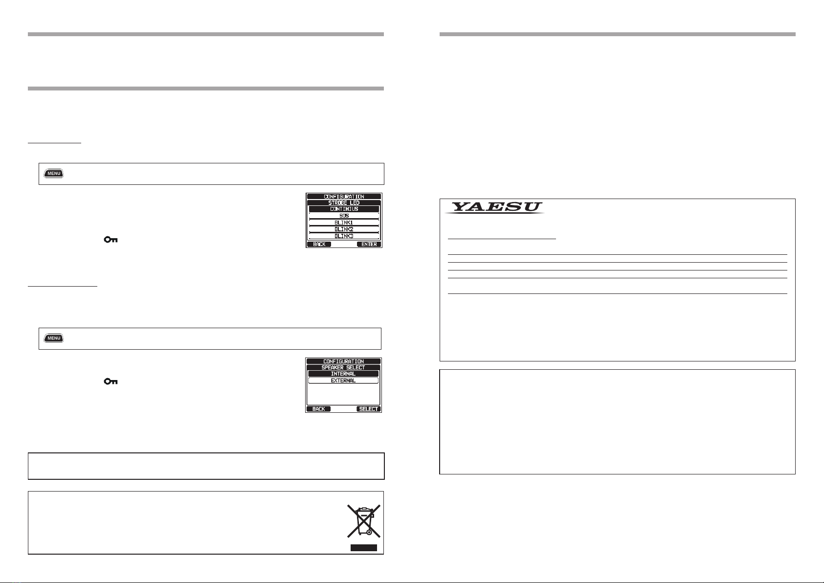
Strobe LED
When the [STROBE] soft key is pressed, the Strobe LED will light and ash repeatedly.
1. []  “SETUP” “CONFIGURATION” “STROBE LED”
2. Rotate the DIAL/ENT knob to select the desired setting. The available
Strobe settings are: “CONTONIOUS” (default setting), “SOS”, “BLINK 1”,
“BLINK 2”, or “BLINK 3”.
3. Press the [ENTER] soft key to store the selected setting.
4. Press the CLEAR/ key to return to radio operation.
5. When the [STROBE] soft key is pressed, the Strobe LED will light or ash
repeatedly.
Speaker Select
The SSM-70H microphone can drive either the internal speaker or the external speaker. When
connecting an external speaker, follow the procedure below to mute the SSM-70H speaker and enable
the external speaker that is connected to the wires on the SSM-70H routing cable.
1. [ ]  “SETUP” “CONFIGURATION” “SPEAKER SELECT”
2. Rotate the DIAL/ENT knob to select “INTERNAL” or “EXTERNAL”, then
press the [SELECT] soft key.
3. Press the CLEAR/ key to return to radio operation.
YAESU MUSEN CO., LTD.
Tennozu Parkside Building
2-5-8 Higashi-Shinagawa, Shinagawa-ku, Tokyo 140-0002 Japan
YAESU USA
6125 Phyllis Drive, Cypress, CA 90630, U.S.A.
YAESU UK
Unit 12, Sun Valley Business Park, Winnall Close
Winchester, Hampshire, SO23 0LB, U.K.
1904L-BS
This equipment has been tested and found to comply with the limits for a Class B digital device, pursuant to Part
15 of the FCC Rules. These limits are designed to provide reasonable protection against harmful interference in a
residential installation. This equipment generates, uses and can radiate radio frequency energy and, if not installed
and used in accordance with the instructions, may cause harmful interference to radio communications. However,
there is no guarantee that interference will not occur in a particular installation.
If this equipment does cause harmful interference to radio or television reception, which can be determined by
turning the equipment off and on, the user is encouraged to try to correct the interference by one or more of the
following measures:
• Reorient or relocate the receiving antenna.
• Increase the separation between the equipment and receiver.
• Connect the equipment into an outlet on a circuit different from that to which the receiver is connected.
• Consult the dealer or an experienced radio/TV technician for help.
Declaration of Conformity
Type of Equipment: Remote Station Microphone
Brand Name: STANDARD HORIZON
Model Number: SSM-70H
Manufacturer: YAESU MUSEN CO., LTD.
Address of Manufacturer: Tennozu Parkside Building, 2-5-8 Higashi-Shinagawa,
Shinagawa-ku,Tokyo 140-0002 Japan
This device complies with part 15 of the FCC Rules. Operation is subject to the following two conditions; (1)this
device may not cause harmful interference, and (2) this device must accept any interference received, including
interference that may cause undesired operation.
The technical documentation as required by the Conformity Assessment procedures is kept at the following address:
Company: Yaesu U.S.A.
Address: 6125 Phyllis Drive, Cypress, CA 90630, U.S.A.
Telephone: (714) 827-7600
Changes or modifications to this device not expressly approved by YAESU MUSEN could void the user’s
authorization to operate this device.
Specications
Supply voltage ....................................................................... 13.8 VDC (Supplied from the transceiver)
Current consumption ................................................................ 400 mA @VOL Max. (Internal Speaker)
550 mA @VOL Max. (External Speaker)
200 mA @AF Mute
Operating Temperature ................................................................... –4 °F to +140 °F (–20 °C to +60 °C)
MIC. Sensitivity (Typical)........................................................ 130 mVrms @ 1 kHz Tone with 94 dB(A)
MIC. Impedance ....................................................................................................................... 2 k ohms
AF output ................................................................ 2.0 W @ 8 ohms for 10 % THD (Internal Speaker)
2.4 W @ 4 ohms for 10 % THD (External Speaker)
Display Size (Approx)........................................................................................ 1.7” x 1.2” (44 x 32 mm)
Display Resolution ........................................................................................................... 222 x 162 dots
Case Size ................................................................................... 2.5” x 5.3” x 1.3” (63 x 135 x 32.5 mm)
Weight (Approx)............................................................................................................. 13.05 oz (370 g)
Disposal of Electrical and Electronic Equipment
Products with the symbol (crossed-out wheeled bin)cannot be disposed of as household waste.
Electronic and Electrical Equipment should be recycled at a facility capable of handling these
items and their waste byproducts.
Please contact a local equipment supplier representative or service center for information about
the waste collection system in your country.
*EBA28X101*
EBA28X101
Printed in Japan

This manual suits for next models

1

Other Standard Horizon Microphone manuals

Standard Horizon RAM3 User manual

Standard Horizon

Standard Horizon RAM3 User manual

Standard Horizon RAM3+ User manual

Standard Horizon

Standard Horizon RAM3+ User manual

Standard Horizon RAM4 SSM-70H Instruction Manual

Standard Horizon

Standard Horizon RAM4 SSM-70H Instruction Manual

Standard Horizon SSM-71H User manual

Standard Horizon

Standard Horizon SSM-71H User manual

Standard Horizon RAM4X User manual

Standard Horizon

Standard Horizon RAM4X User manual

Standard Horizon RAM4 User manual

Standard Horizon

Standard Horizon RAM4 User manual

Standard Horizon RAM3 User manual

Standard Horizon

Standard Horizon RAM3 User manual

Popular Microphone manuals by other brands

Sony ECM PC50 operating instructions

Sony

Sony ECM PC50 operating instructions

Shure Easyflex EZG-SE Series user guide

Shure

Shure Easyflex EZG-SE Series user guide

Phenyx PTM-11 owner's manual

Phenyx

Phenyx PTM-11 owner's manual

Neumann.Berlin KM 54 datasheet

Neumann.Berlin

Neumann.Berlin KM 54 datasheet

Component Solution Services Verity SM05J manual

Component Solution Services

Component Solution Services Verity SM05J manual

TONOR TW822 instruction manual

TONOR

TONOR TW822 instruction manual

Behringer ULTRALINK ULM100USB manual

Behringer

Behringer ULTRALINK ULM100USB manual

Dictaphone PowerMic installation guide

Dictaphone

Dictaphone PowerMic installation guide

Audio Technica M3 Setup and operation

Audio Technica

Audio Technica M3 Setup and operation

JTS KA-8TH/1 manual

JTS

JTS KA-8TH/1 manual

Omnitronic MIC 77H quick start guide

Omnitronic

Omnitronic MIC 77H quick start guide

STUDIO PROJECTS LSM user manual

STUDIO PROJECTS

STUDIO PROJECTS LSM user manual

Shure PGA27 user guide

Shure

Shure PGA27 user guide

Shure MV7 user guide

Shure

Shure MV7 user guide

Somogyi home MVN01 instruction manual

Somogyi

Somogyi home MVN01 instruction manual

BRUEL & KJAER 4952 Notes for users

BRUEL & KJAER

BRUEL & KJAER 4952 Notes for users

American Audio WR 90E user guide

American Audio

American Audio WR 90E user guide

Telex Series 750 Technical data

Telex

Telex Series 750 Technical data

manuals.online logo
manuals.online logoBrands
  • About & Mission
  • Contact us
  • Privacy Policy
  • Terms and Conditions

Copyright 2025 Manuals.Online. All Rights Reserved.