Standfast TRAM TR-01 User manual

TR-06-M-002 Rev C
TRAM Safety System
TRAM Safety SystemTRAM Safety System
TRAM Safety System
Technical Manual
Technical ManualTechnical Manual
Technical Manual
TR
TRTR
TR-
--
-01, 02
01, 02 01, 02
01, 02
Standard and Fixed Base TRAMs
Standard and Fixed Base TRAMsStandard and Fixed Base TRAMs
Standard and Fixed Base TRAMs
TR
TRTR
TR-
--
-00
0000
00-
--
-01, 02, 03, 04
01, 02, 03, 0401, 02, 03, 04
01, 02, 03, 04
Standard, xtended, and Rotating Arms
Standard, xtended, and Rotating ArmsStandard, xtended, and Rotating Arms
Standard, xtended, and Rotating Arms

- 2 –
TR-06-M-002 Rev D 2019
Disclaimer and Copyright Notice
Disclaimer and Copyright NoticeDisclaimer and Copyright Notice
Disclaimer and Copyright Notice
1. The purpose of this Manual is to provide information about the Standfast TRAM Safety System. It is not
exhaustive in its coverage of rights or obligations nor is it legal advice.
2. This Manual has no legal status or legal effect whatsoever. Any reference to systems to prevent falls is for
guidance only. Readers of this Manual should seek appropriate guidance from the appropriate Regulatory
Authority as well as obtain appropriate legal advice in respect of the application of the legislation and
regulation in respect of the safety system.
3. This Manual may be affected by changes to Legislation or Regulation. Standfast nterprises Pty Ltd and
Standfast Corporation Pty Ltd (Standfast) accepts no responsibility for the accuracy, completeness or
currency of the material included in this Manual.
4. Users of this Manual are encouraged to obtain professional advice on the relevant Legislation and
Regulations and to exercise their own skill and care in relation to any material contained in this Manual.
5. Standfast disclaims all liability or responsibility for any loss or damages arising out of any use, or reliance
on, this Manual.
6. This Manual is copyright. You may use and reproduce this material in an unaltered form only for your
personal non-commercial use or non-commercial use within your organisation. Apart from any use
permitted under the Copyright Act 1968, all other rights are reserved. Requests for other types of use
should be directed to Standfast.
7. TRAM is a trademark of Standfast nterprises Pty Ltd.

- 3 –
TR-06-M-002 Rev D 2019
1
11
1R ADING TH DOCUM NTATION
R ADING TH DOCUM NTATIONR ADING TH DOCUM NTATION
R ADING TH DOCUM NTATION
1.1
1.11.1
1.1 LIT RATUR INFORMATION
LIT RATUR INFORMATIONLIT RATUR INFORMATION
LIT RATUR INFORMATION
This manual contains safety information and instructions for operation and maintenance of the Standfast TRAM
System. This Manual should be stored in an area where it is accessible to those responsible for maintenance of
the equipment.
The information, specifications, and illustrations in this publication are provided based on information available at
the time of writing. Continued improvement and advancement of product design may have caused changes to
your TRAM System, which are not included in this Manual.
Some photographs or illustrations in this Manual show details or attachments that may be different from your
TRAM system:
•Subassemblies, guards or covers may have been removed for illustrative purposes.
•The specifications, torques, pressures, measurements, adjustments, illustrations, and other items can
change at any time.
Important!
Important! Important!
Important! These changes can affect the service given to the product.
Whenever a question arises regarding your TRAM System or this Manual, and before starting any job, please
consult your Standfast TRAM dealer to obtain the complete and most current information available.
1.2
1.21.2
1.2 AL RTS US D IN THIS MANUAL
AL RTS US D IN THIS MANUALAL RTS US D IN THIS MANUAL
AL RTS US D IN THIS MANUAL
Please read the list below of alerts used in this manual. These alerts are used to indicate important instructions.
Be sure to obey these instructions.
Alert
AlertAlert
Alert
Meaning
MeaningMeaning
Meaning
Indicates a warning
warningwarning
warning concerning an operation or hazard
that may lead to death or injury to persons if not
performed correctly or with due care. Always pay
attention to these warnings.
Important
ImportantImportant
Important!
!!
!
Indicates a
restriction or important information. Be certain
to read these items to avoid improper use or damage to
the equipment.
Note
NoteNote
Note!
!!
!
Indicates additional information or explanation. Be certain
to read these items.

- 4 –
TR-06-M-002 Rev D 2019
2
22
2IMPORTANT SAF TY INFORMATION
IMPORTANT SAF TY INFORMATIONIMPORTANT SAF TY INFORMATION
IMPORTANT SAF TY INFORMATION
2.1
2.12.1
2.1 G N RAL
G N RALG N RAL
G N RAL
The purpose of the TRAM Safety System is to protect the user from a fall from height. If the system is not properly
used, maintained or repaired, it may no longer protect against a fall from height.
Failure to follow the instructions or heed the warnings contained in this manual could result in injury or death.
Improper operation, maintenance or repair of this product can be dangerous and could result in injury or death.
All work must comply with the safety regulations of the jurisdiction in which the TRAM System is installed and
operated, including industry Codes of Practice and Standards.
No one should make any alterations or additions to the equipment. Any repair shall only be carried out in
accordance with authorized procedures.
The TRAM shall not be used outside its limitations as described in this Manual, or for any purpose other than that
for which it is intended.
Most accidents involving product operation, maintenance and repair are caused by failure to observe basic safety
rules or precautions. An accident can often be avoided by recognizing potentially hazardous situations before an
accident occurs.
Standfast Corporation cannot anticipate every possible circumstance that might involve a potential hazard. The
warnings in this publication and on the product are therefore not all inclusive. If a tool, procedure, work method
or operating technique not specifically recommended by Standfast Corporation is used, you must satisfy yourself
that it is safe for you and others. You should also ensure that the product will not be damaged or made unsafe by
the operation, lubrication, maintenance or repair procedures you choose.
All inspection, maintenance, servicing and repair work on the TRA System shall be
carried out by a Competent Person
Competent PersonCompetent Person
Competent Person.
A Competent Person
Competent PersonCompetent Person
Competent Person is defined as a person:
•who is knowledgeable of recommendations and instructions on the TRA
System issued by Standfast (including the information contained in this
manual)
•who has the necessary training, skills and tools to perform the work properly,
•who can identify existing and predictable defects and hazards in any
component of the TRA safety system and related equipment used in the
work environment,
•who is authorised to take prompt corrective action to eliminate or control
hazards, and has the skills and resources to do so,
•who is familiar with relevant guidelines and national and international safety
regulations.
*Your Standfast TRAM Dealer is authorised to carry out all inspection, maintenance, servicing and repair
work on the TRAM System
Your Standfast TRAM Dealer may also be contacted to authorise a Competent Person.

- 5 –
TR-06-M-002 Rev D 2019
2.2
2.22.2
2.2 SAF TY SIGNS AND LAB LS
SAF TY SIGNS AND LAB LSSAF TY SIGNS AND LAB LS
SAF TY SIGNS AND LAB LS
Safety precautions and warnings are provided in this manual and on the product. If these hazard warnings are not
heeded the product may not protect you or others from bodily injury or death.
The TRAM system is permanently marked or labelled to indicate its purpose, correct use, limitations and other
relevant information aimed at reducing the incidence of misuse or misfitting of the equipment.
Make sure that all safety signs can be read. Clean or replace these if illegible. When cleaning the labels use a
cloth, water and soap. Do not use solvents, gasoline, etc to clean safety signs.
Contact your Standfast TRAM Dealer to organise replacement signs and labels.
2.3
2.32.3
2.3 SAF WORKING AT H IGHTS
SAF WORKING AT H IGHTSSAF WORKING AT H IGHTS
SAF WORKING AT H IGHTS
The operation and maintenance of the TRAM must comply with the safety Legislation and Regulations of the
jurisdiction in which it is used.
Users of the TRAM System must be properly trained and competent. Further enquiries regarding training
materials and courses should be directed to your Standfast TRAM Dealer or by email to: info@standfastcorp.eu
The TRAM restraint belt must only be used when the TRAM system is used as a total restraint system. The TRAM
restraint belt must not be used if there is a risk of free fall.
Total restraint means that there is no risk of fall as the user is prevented from reaching a fall edge. This is achieved
through combination of anchor point location and lanyard length.
2.4
2.42.4
2.4
FALL ARR ST
FALL ARR STFALL ARR ST
FALL ARR ST
It is essential for safety that if the TRAM
It is essential for safety that if the TRAMIt is essential for safety that if the TRAM
It is essential for safety that if the TRAM
System
SystemSystem
System
is used as a fall
is used as a fallis used as a fall
is used as a fall-
--
-arrest system a full body harness and energy
arrest system a full body harness and energy arrest system a full body harness and energy
arrest system a full body harness and energy
absorber should be used
absorber should be usedabsorber should be used
absorber should be used.
The TRAM Belt described in this Manual is for use in total restraint and must NOT be used in fall arrest.
The TRAM Belt described in this Manual is for use in total restraint and must NOT be used in fall arrest.The TRAM Belt described in this Manual is for use in total restraint and must NOT be used in fall arrest.
The TRAM Belt described in this Manual is for use in total restraint and must NOT be used in fall arrest.
In fall arrest applications, the TRAM System should always be positioned, and the work carried out in such a way,
as to minimise both the potential for falls and potential fall distance.
When the TRAM system is used as a fall-arrest system consideration should be given as to how any necessary
rescue could be safely achieved.
The operator should ensure that when the TRAM is used as a fall-arrest system that the distance required or
necessary to arrest the fall of a falling worker does not exceed the distance available on site.
If the TRAM has been used to arrest a fall it should be not used again until it is confirmed in writing by a
competent person that it is acceptable to do so.
2.5
2.52.5
2.5 PR
PRPR
PR -
--
-US CH CK
US CH CKUS CH CK
US CH CK
Users must carry out a Pre-Use Check of the equipment, as per the instructions in this Manual, to ensure that it is
in a serviceable condition and operates correctly before use.

- 6 –
TR-06-M-002 Rev D 2019
It is essential for safety that equipment is withdrawn from use immediately should any doubt arise about its
condition for safe use.
2.6
2.62.6
2.6 S RVICING
S RVICINGS RVICING
S RVICING
Servicing should be carried out at regular intervals as described in this Manual.
Services should only be conducted by a Competent Person and strictly in accordance with servicing procedures.
quipment Records of Periodic and Overhaul Services must be maintained and be available to the user.
2.7
2.72.7
2.7 INSTALLATION
INSTALLATIONINSTALLATION
INSTALLATION
Anyone installing the TRAM system must read, understand and strictly adhere to the instructions and safety
information in this manual and any Installation Instructions for the TRAM Safety system.
The installer must verify the adequacy of anchor point(s) either by calculation or by carrying out a test in a sample
of the material in compliance with the specifications of the appropriate Standards.
2.8
2.82.8
2.8 MAINT NANC & R PAIR
MAINT NANC & R PAIRMAINT NANC & R PAIR
MAINT NANC & R PAIR
Attach a DO NOT OP RAT or similar warning tag to start switch or controls before performing maintenance or
repairing the TRAM, if it is a vehicular installation. When appropriate, attach tags at the engine and at each user’s
position and disconnect starting controls. nsure any protective locks, controls or inhibitors are in the applied
position before commencing work.
Some installations will require the use of fall protection equipment during removal and installation of the TRAM
system. A service platform or walkway is recommended.
It is the responsibility of the owner to ensure that access is achieved in accordance with local regulations and
standards.
Wear a hard hat, protective glasses, hearing protection, gloves and other protective equipment as required by job
conditions.
Do not wear loose clothing or jewellery that can catch on controls or other parts of the TRAM.
Use caution when removing springs. Gradually loosen (do not remove) the last bolts or nuts located at opposite
ends of any spring energy device, until all elastic energy is dissipated, before completely removing the fasteners.
Do not carry out hot work on the TRAM device without first consulting your Standfast TRAM Dealer. Your TRAM
contains plastic components that may not function correctly in the event that hot work is carried out on the
TRAM.
Compressed air can cause personal injury. When using compressed air for cleaning, wear a protective face shield,
protective clothing and protective shoes. The maximum air pressure must be below 200 kPa (30 psi) for cleaning
purposes.
Wear eye protection at all times when cleaning the TRAM system with hot and/or pressurised water. Pressurised
water could cause debris and/or hot water to be blown at the worker and result in personal injury.

- 7 –
TR-06-M-002 Rev D 2019
scaping fluid under pressure, even a pin-hole size leak, can penetrate body tissue, causing serious injury or
possible death. If fluid is injected into your skin, it must be treated by a doctor familiar with this type of injury
immediately.
The TRAM System and replacement parts (e.g. brake pads) shipped from the factory are asbestos free.
Support equipment and attachments correctly when working beneath them.
Do not allow unauthorized personnel on or around the TRAM when it is being serviced.
Do not attempt repairs you do not understand.
The list of warnings above is not exhaustive. It is the responsibility of the user or maintenance personal performing
the work to identify, mitigate and prevent all hazards while preforming the work.

- 8 –
TR-06-M-002 Rev D 2019
3.
3.3.
3. CONT NTS
CONT NTSCONT NTS
CONT NTS
Contents
1
11
1
READING THE DOCU ENTATION
READING THE DOCU ENTATIONREADING THE DOCU ENTATION
READING THE DOCU ENTATION................................................................................................ 3
1.1 LIT RATUR INFORMATION.................................................................................................................3
1.2 AL RTS US D IN THIS MANUAL........................................................................................................3
2
22
2
I PORTANT SAFETY INFOR ATION
I PORTANT SAFETY INFOR ATIONI PORTANT SAFETY INFOR ATION
I PORTANT SAFETY INFOR ATION ............................................................................................4
2.1 G N RAL.........................................................................................................................................4
2.2 SAF TY SIGNS AND LAB LS..............................................................................................................5
2.3 SAF WORKING AT H IGHTS ............................................................................................................5
2.4 FALL ARR ST ...................................................................................................................................5
2.5 PR -US CH CK...............................................................................................................................5
2.6 S RVICING.......................................................................................................................................6
2.7 INSTALLATION.................................................................................................................................6
2.8 MAINT NANC & R PAIR.................................................................................................................6
3.
3.3.
3.
CONTENTS
CONTENTSCONTENTS
CONTENTS .................................................................................................................................8
4
44
4
INTRODUCTION
INTRODUCTIONINTRODUCTION
INTRODUCTION........................................................................................................................ 10
4.1 SAF TY..........................................................................................................................................10
4.2 COMPLIANC TO WORKPLAC SAF TY LAWS.................................................................................10
4.3 CUSTOM R S RVIC ......................................................................................................................10
5
55
5
DESCRIPTION OF EQUIP ENT
DESCRIPTION OF EQUIP ENTDESCRIPTION OF EQUIP ENT
DESCRIPTION OF EQUIP ENT................................................................................................... 11
5.1 TRAM SYST M D SCRIPTION..........................................................................................................11
5.2 TRAM UNIT D SCRIPTION ..............................................................................................................12
5.2.1
TRA odel (Base) Types.............................................................................................................................. 12
5.2.2
TRA Option (Arm) Types ............................................................................................................................. 12
5.3 TRAM UNIT NUMB RING SYST M...................................................................................................13
5.4 L FT AND RIGHT HAND CONFIGUATION........................................................................................14
5.5 F ATUR S & CONTROLS ................................................................................................................14
5.6 TRAM UNIT LAB LING....................................................................................................................18
5.7 TRAM B LT LAB L..........................................................................................................................19
5.8 TRAM INSTALLATION PLAT ..........................................................................................................20
6
66
6
OPERATION
OPERATIONOPERATION
OPERATION .............................................................................................................................. 21
6.1 G N RAL OP RATION ...................................................................................................................21
6.2 OP RATING TH ROTARY JOINT (TR-00-03 & 04 TRAM OPTIONS (ARMS) ONLY) .............................25
6.3 OP RATING TH BRAK OV RRID .................................................................................................25
7
77
7
INSPECTION &
INSPECTION & INSPECTION &
INSPECTION & AINTENANCE
AINTENANCEAINTENANCE
AINTENANCE.................................................................................................. 26
7.1 INSP CTION & MAINT NANC ACTIVITI S & SCH DUL .................................................................26
7.2 MAINT NANC R CORDS ..............................................................................................................28
8
88
8
TRA CLEANING PROCEDURES
TRA CLEANING PROCEDURESTRA CLEANING PROCEDURES
TRA CLEANING PROCEDURES................................................................................................. 29
8.1 TRAM Belt Cleaning Procedure .......................................................................................................29
8.2 TRAM D VIC CL ANING PROC DUR ...........................................................................................29
8.3 TRAM INSTALLATION CL ANING PROC DUR ................................................................................29

- 9 –
TR-06-M-002 Rev D 2019
9
99
9
SERVICING INSTRUCTIONS
SERVICING INSTRUCTIONSSERVICING INSTRUCTIONS
SERVICING INSTRUCTIONS ....................................................................................................... 31
9.1 FAST N R TORQU S TTINGS........................................................................................................32
9.2 THR ADLOCKING ADH SIV ..........................................................................................................32
9.3 S RVICING TH TRAM B LT............................................................................................................33
9.3.1
PERIODIC SERVICE – TRA BELT ................................................................................................................... 33
9.3.2
OVERHAUL SERVICE – TRA BELT................................................................................................................. 34
9.4 S RVICING TH TRAM ARM............................................................................................................35
9.4.1
PERIODIC SERVICE – TRA AR ................................................................................................................... 35
9.4.2
OVERHAUL SERVICE – TRA AR ................................................................................................................. 38
9.4.3
CLUTCH PIN ADJUST ENT PROCEDURE ....................................................................................................... 39
9.5 S RVICING TH TRAM TROLL Y......................................................................................................43
9.5.1
PERIODIC SERVICE – TRA TROLLEY............................................................................................................. 44
9.5.2
OVERHAUL SERVICE – TRA TROLLEY .......................................................................................................... 45
9.5.3
Vertical ‘PLAY’ IN THE TRA AR .................................................................................................................. 45
9.5.4
PROCEDURE: ADJUST ENT OF THE TRA WHEEL SET .................................................................................. 45
9.5.5
PROCEDURE: REPLACE ENT OF THE TRA WHEEL SET TR-40-07 ................................................................. 48
9.6 S RVICING TH TRAM BRAK SYST M ............................................................................................48
9.6.1
PERIODIC SERVICE – TRA BRAKE SYSTE ................................................................................................... 51
9.6.2
OVERHAUL SERVICE – TRA BRAKE SYSTE ................................................................................................. 52
9.6.3
BRAKE ADJUST ENT PROCEDURE................................................................................................................. 53
9.6.4
PROCEDURE: REPLACE ENT OF THE TYPE I BRAKE CABLE WITH THE TYPE II ................................................. 56
9.6.5
PROCEDURE: TO REPLACE THE TYPE II BRAKE CABLE..................................................................................... 64
S RVICING TH TRAM INSTALLATION .......................................................................................................67
9.6.6
PERIODIC SERVICE – TRA INSTALLATION.................................................................................................... 67
9.6.7
OVERHAUL SERVICE – TRA INSTALLATION ................................................................................................. 68
10
1010
10
REPAIRS TO THE TRA SYSTE
REPAIRS TO THE TRA SYSTEREPAIRS TO THE TRA SYSTE
REPAIRS TO THE TRA SYSTE ............................................................................................. 69
10.1 DAMAG TO TH TRAM SYST M....................................................................................................69
10.2 TH R PAIR PROC SS ....................................................................................................................69
10.3 V RIFICATION OF R PAIRS.............................................................................................................69
11
1111
11
REPLACE ENT & SPARE PARTS
REPLACE ENT & SPARE PARTSREPLACE ENT & SPARE PARTS
REPLACE ENT & SPARE PARTS ................................................................................................. 70
11.1 ORD RING PARTS..........................................................................................................................70
11.2 SPAR PARTS LIST..........................................................................................................................70
12
1212
12
RECERTIFICATION OF THE TRA SYSTE
RECERTIFICATION OF THE TRA SYSTERECERTIFICATION OF THE TRA SYSTE
RECERTIFICATION OF THE TRA SYSTE .................................................................................. 71
13
1313
13
SPECIFICATIONS
SPECIFICATIONSSPECIFICATIONS
SPECIFICATIONS .................................................................................................................... 72
APPENDIX A
APPENDIX A APPENDIX A
APPENDIX A –
––
–
TRA PRE
TRA PRETRA PRE
TRA PRE-
--
-USE CHECK PROCEDURE
USE CHECK PROCEDUREUSE CHECK PROCEDURE
USE CHECK PROCEDURE .......................................................................... 73
APPENDIX B
APPENDIX B APPENDIX B
APPENDIX B –
––
–
TRA SERVICE TOOLBOX LIST
TRA SERVICE TOOLBOX LISTTRA SERVICE TOOLBOX LIST
TRA SERVICE TOOLBOX LIST ................................................................................... 74
APPENDIX C
APPENDIX C APPENDIX C
APPENDIX C -
--
-
EQUIP ENT RECORD
EQUIP ENT RECORDEQUIP ENT RECORD
EQUIP ENT RECORD ................................................................................................ 75

- 10 –
TR-06-M-002 Rev D 2019
4
44
4INTRODUCTION
INTRODUCTIONINTRODUCTION
INTRODUCTION
4.1
4.14.1
4.1 SAF TY
SAF TYSAF TY
SAF TY
The “Important Safety Information” section lists basic safety precautions. In addition, this section identifies
hazardous situations, which are identified within the text by the highlighted warning symbol. Read and understand
the basic precautions listed in the “Important Safety Information” section before using or performing maintenance
or repair of this product.
4.2
4.24.2
4.2 COMPLIANC TO WORKPLAC SAF TY LAWS
COMPLIANC TO WORKPLAC SAF TY LAWS COMPLIANC TO WORKPLAC SAF TY LAWS
COMPLIANC TO WORKPLAC SAF TY LAWS
The use and maintenance of the TRAM Safety System must comply with the Workplace Safety Legislation and
Regulations of the jurisdiction in which the TRAM System is used.
The TRAM System have been tested to the specifications of, and are compliant with:
• ANSI Z359 as both a fall restraint (w/ belt) or arrest (w/ harness) device.
• N 795 Type D anchor point
• AS/NZS 1891.2
4.3
4.34.3
4.3 CUSTOM R S RVIC
CUSTOM R S RVICCUSTOM R S RVIC
CUSTOM R S RVIC
Your satisfaction is a primary concern to Standfast and its dealers. When a problem arises concerning the sale,
operation or service of your TRAM System, please contact the Standfast TRAM Dealer in your area.
The Standfast TRAM Dealer nearest to you can be located by consulting the website: www.standfastcorp.eu
Standfast may be contacted directly by email or phone by consulting the website: www.standfastcorp.eu

- 11 –
TR-06-M-002 Rev D 2019
5
55
5D SCRIPTION OF QUIPM NT
D SCRIPTION OF QUIPM NTD SCRIPTION OF QUIPM NT
D SCRIPTION OF QUIPM NT
This chapter describes the different base and arm types of the TRAM family of products and provides the names
and location of major components and describes their functions.
5.1
5.15.1
5.1 TRAM SYST M D SCRIPTION
TRAM SYST M D SCRIPTIONTRAM SYST M D SCRIPTION
TRAM SYST M D SCRIPTION
The TRAM Safety System described in this publication is a total restraint height safety system. It is designed for
various industrial, mining, defence, transport, and domestic height safety applications to provide the user with an
ideal system of mobility, stability and restraint.
The TRAM (Safety) System consists of three components: the TRAM
TRAMTRAM
TRAM
Unit
UnitUnit
Unit, the TRAM Belt
TRAM BeltTRAM Belt
TRAM Belt/Harness
/Harness/Harness
/Harness and the TRAM
TRAM TRAM
TRAM
Rail
RailRail
Rail.
Figure 5.1 The TRAM Safety System
The TRAM
TRAMTRAM
TRAM
Unit
UnitUnit
Unit (or TRAM D
TRAM DTRAM D
TRAM Device
eviceevice
evice) is a mobile anchor point and handhold that is either fixed or moves along a
TRAM Rail. For inspection, maintenance and repair purposes, the TRAM Unit is classified into two assemblies –
the TRAM Model (Base) and the TRAM Option (Arm). The TRAM Model (Base) is further divided in two
subassemblies, the TRAM Trolley and the TRAM Brake System.
The TRAM Belt
TRAM BeltTRAM Belt
TRAM Belt is a restraint belt that is worn by the user and attached to the TRAM by two lanyards. (May also
but used with a full body harness in Fall Arrest situations)
The TRAM
TRAM TRAM
TRAM Rail
RailRail
Rail consists of the fixed rail and/or the mounting hardware which attaches the rail or TRAM Unit to the
structure or vehicle to which the TRAM System is fitted.
TRAM
Belt
TRAM
Trolley
TRAM Brake
System
TRAM Installation
TRAM Unit
TRAM Option (Arm)

- 12 –
TR-06-M-002 Rev D 2019
5.2
5.25.2
5.2 TRAM UNIT
TRAM UNIT TRAM UNIT
TRAM UNIT D SCRIPTION
D SCRIPTIOND SCRIPTION
D SCRIPTION
The TRAM Safety System is designed to be both interchangeable and flexible. Most TRAM Options (Arms) can be
fitted either to a TR-01 Standard TRAM or TR-02 Fixed Base TRAM while the TR-03 Rotating Base TRAM has
purpose-built TRAM Options (Arms). All of these TRAM Options (Arms) can be installed in either a Right- or Left-
Hand configuration.
5.2.1
5.2.15.2.1
5.2.1 TRAM
TRAMTRAM
TRAM
Model
ModelModel
Model
(
((
(Base
BaseBase
Base)
))
)
Types
TypesTypes
Types
TR-01 TR-02 TR-03
Standard TRAM Fixed Base TRAM Rotating Base TRAM
5.2.2
5.2.25.2.2
5.2.2 TRAM
TRAM TRAM
TRAM Option (
Option (Option (
Option (Arm
ArmArm
Arm)
))
)
Types
TypesTypes
Types
TR-00-01 TR-00-02 TR-00-03
Standard Arm xtended Arm Rotating Arm
TR-00-04 TR-00-30 T12-00-31 xtended Rotating Arm Std. Rotating
Base Arm Shortened Rotating
Base Arm

- 13 –
TR-06-M-002 Rev D 2019
5.3
5.35.3
5.3 TRAM UNIT NUMB RING SYST M
TRAM UNIT NUMB RING SYST MTRAM UNIT NUMB RING SYST M
TRAM UNIT NUMB RING SYST M
Complete TRAM units are numbered with a designation which is a combination of the TRAM Model (Base) and
TRAM Option (Arm) numbers followed by a Left- or Right-Hand indication where applicable.
TR
TRTR
TR-
--
-01
0101
01-
--
-02
0202
02-
--
-RH
RHRH
RH
TR
TRTR
TR-
--
-02
0202
02-
--
-03
0303
03
TR
TRTR
TR-
--
-03
0303
03-
--
-30
3030
30-
--
-LH
LHLH
LH
TRAM Right Handed
Standard Base
Extended Arm
- 14 –
TR-06-M-002 Rev D 2019
5.4
5.45.4
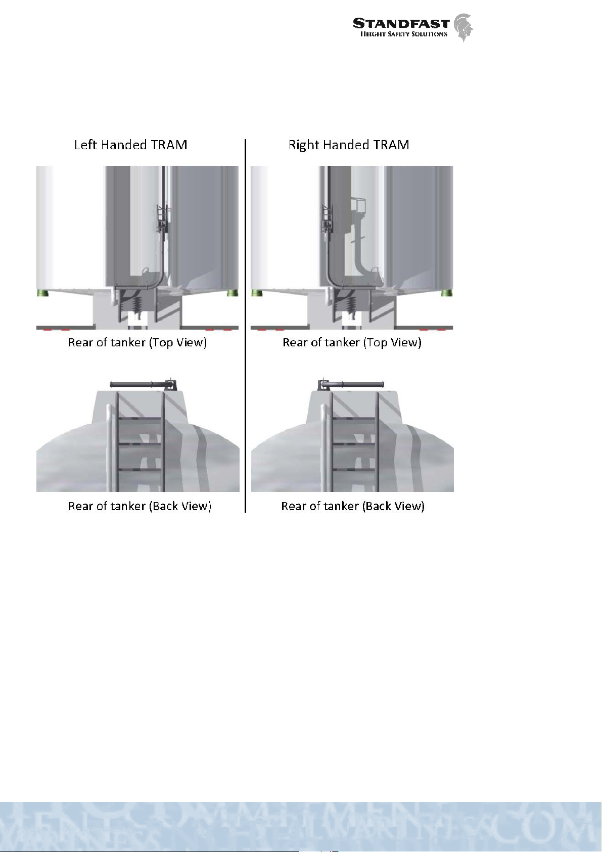
5.4 L FT AND RIGHT HAND CONFIGUATION
L FT AND RIGHT HAND CONFIGUATIONL FT AND RIGHT HAND CONFIGUATION
L FT AND RIGHT HAND CONFIGUATION
Whether a TRAM is Left or Right-handed is determined by the direction the end of the arm is pointing when
facing it from the entry point.
5.5
5.55.5
5.5 F ATUR S & CONTROLS
F ATUR S & CONTROLSF ATUR S & CONTROLS
F ATUR S & CONTROLS
Refer to Figures 5.3 and 5.4 to identify the features and control components of the TRAM System. Figure 5.3
illustrates a TR-01-03 Standard TRAM Rotating Arm. Figure 5.4 illustrates a TR-03-30 Rotating Base TRAM
Standard Rotating Base Arm. Not all controls are present on all units, however all controls on TRAM family
products are illustrated in the figures below.

- 15 –
TR-06-M-002 Rev D 2019
Figure 5.3 Features and Controls of the TRAM System – TR-01-03
(Also applies to TR-01-01&02 units excluding Rotating Joint)
Belt
Lanyard
Rotating Joint
Lever
Attachment Ring
Double Action Snap Hook
Brake Lever
Clutch Lever
Rotating Joint
Gas Strut
Brake Override
Lever
Rail

- 16 –
TR-06-M-002 Rev D 2019
Figure 5.4 Features and Controls of the TRAM System – TR-03-30-LH
Rotary Joint
Rotary JointRotary Joint
Rotary Joint (Install on TRAM Options (Arms) TR-00-03&04 only)
The Rotary Joint allows the horizontal segment of the Arm to rotate relative to the TRAM base. By activating the
Rotary Joint Lever, the Arm can be rotated through 180 degrees, in 90 degree increments. This is illustrated in
Figure 5.3. The joint can be adjusted to allow rotation to any three compass points. * If 270° rotation is needed
inform your TRAM dealer.
0° position 90° position 180° position
Attachment Ring
Brake Lever
Clutch Lever
Lanyard
Gas Strut
Rotating Joint
Release Lever
Brake Override
Lever
Double Action
Snap Hook
- 17 –
TR-06-M-002 Rev D 2019
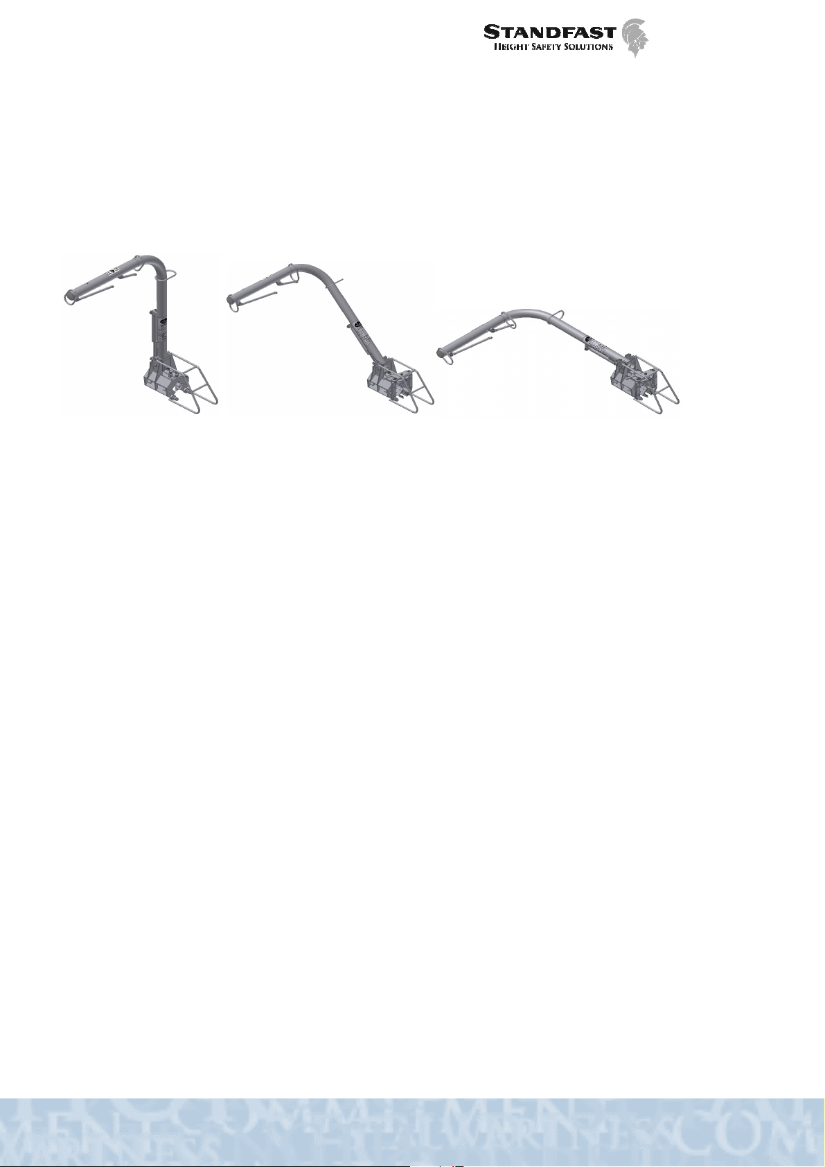
Figure 5.3 Rotating Arm Positions (TR-00-03 & TR-00-04 Series ONLY)
Clutch Lever
Clutch LeverClutch Lever
Clutch Lever
The pivoting movement of the TRAM Arm is controlled by the Clutch lever. Activating the lever allows the user to
pivot the TRAM Arm between vertical and horizontal positions. The arm position can be locked into either the
horizontal, 45 degree or the vertical position and will lock in place in position when the pivot clutch lever is
released. See Figure 5.4.
Figure 5.5 TRAM Arm positions
Brake
BrakeBrake
Brake
Lever
LeverLever
Lever
In its normal position, the Brake system is locked and the TRAM Device is locked in its location on the TRAM rail.
Activating the Brake lever releases the TRAM Device from its locked position and allows it to move along the rail
with the user. Releasing the Brake lever locks the brake system and TRAM onto the rail.
Rotating Base
Rotating Base Rotating Base
Rotating Base Joint
JointJoint
Joint
Lever
LeverLever
Lever
The rotation of the TRAM Arm around the vertical axis of the base is controlled by the Rotating Base Release
Lever. Activating the lever releases a pin which allows the TRAM Option (Arm) to rotate. Once the lever is
released a spring reengages the pin locking the TRAM Arm in place.
Attachment Rings
Attachment RingsAttachment Rings
Attachment Rings
Attachment Rings are anchor points provided on the TRAM Arm for attachment of the Lanyards via the Double-
action Hooks.
Double
DoubleDouble
Double-
--
-A
AA
Action Hooks
ction Hooksction Hooks
ction Hooks
The Double-action Hooks are attached to the end of the lanyards and are used to attach the user to the TRAM
Arm via the Attachment rings.
TRAM
TRAM TRAM
TRAM Belt
BeltBelt
Belt
The TRAM Belt is a purpose designed restraint belt with two lanyards that attach to the TRAM with double action
hooks. The Belt is fixed around the user’s waist using a quick lock and release buckle mechanism and must be
fastened when the Belt is in use
For available TRAM Belt sizes please contact your dealer.
- 18 –
TR-06-M-002 Rev D 2019
Lanyard
LanyardLanyard
Lanyards
ss
s
The lanyards are of fixed length and allow the user to move and work while attached to the TRAM Arm.
Brake Override
Brake OverrideBrake Override
Brake Override
Foot
FootFoot
Foot
Lever
LeverLever
Lever
In its normal position, the Brake system is locked and the TRAM Device is fixed in its location on the TRAM rail. In
the event that the Brake lever fails to function, the Brake override foot-lever may be used to unlock the TRAM
Device from its fixed location, allowing it to move along the rail with the user.
Rail
RailRail
Rail
& Fixtures
& Fixtures& Fixtures
& Fixtures
The Rail provides a path for the TRAM Device to move along. Rail fixtures hold the rail in position and are
designed to comply with Design Strength requirements of legislation. Rail fixtures provide the interface between
the Rail and the structure to which the TRAM is to be fixed.
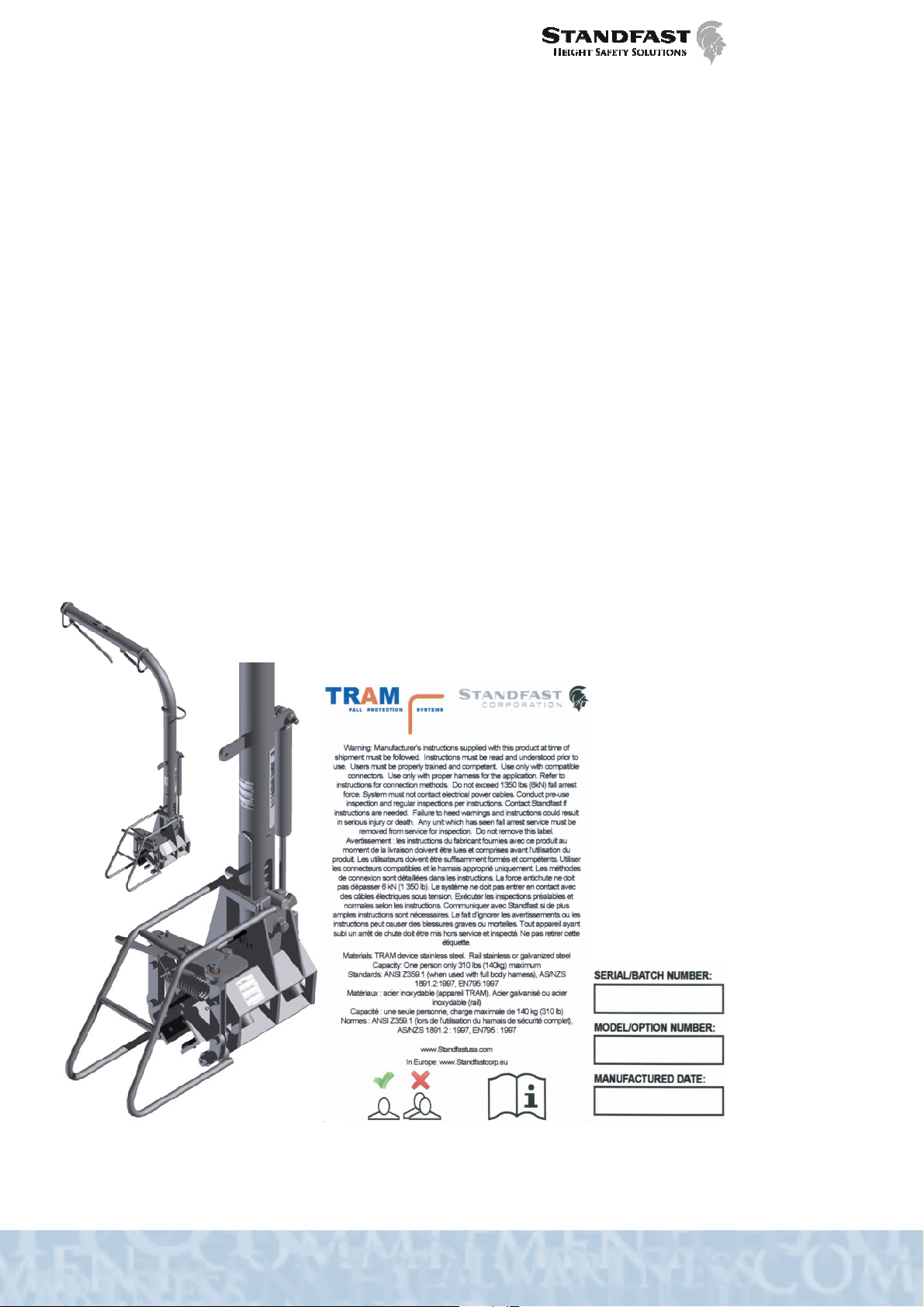
5.6
5.65.6
5.6 TRAM UNIT LAB LING
TRAM UNIT LAB LINGTRAM UNIT LAB LING
TRAM UNIT LAB LING
The TRAM Unit is supplied with the labels illustrated in Figure 5.2.1 below. The labels are usually affixed in the
locations shown but not in all cases. The labels contains important information about the TRAM system including
the type of TRAM Product, a unique serial number, a date of manufacture and a statement of compliance to
legislation.
Important!
Important!Important!
Important! The TRAM Labels are permanently attached to your TRAM system and should not be removed or
modified in any way.
Important!
Important!Important!
Important! The TRAM Labels may vary in design and content subject to Workplace Safety Legislation and
Regulations of the jurisdiction in which the TRAM System is used
Figure 5.2.1 TRAM Unit label locations

- 19 –
TR-06-M-002 Rev D 2019
5.7
5.75.7
5.7 TRAM B LT LAB L
TRAM B LT LAB LTRAM B LT LAB L
TRAM B LT LAB L
The TRAM Belt is supplied with an information label sown into the belt material and illustrated in Figure 5.3.1
below. The label contains important information about the TRAM Belt including a description of the product,
product identification, serial number, date of manufacture and date to be taken out of service, a statement of
compliance to legislation and a pictogram.
Important!
Important!Important!
Important! The TRAM Belt label is permanently attached to your TRAM Belt and should not be removed or
modified in any way.
Important!
Important!Important!
Important! The Installation Plate may vary in design and content subject to Workplace Safety Legislation and
Regulations of the jurisdiction in which the TRAM System is used
Figure 5.3.1 TRAM Belt Label

- 20 –
TR-06-M-002 Rev D 2019
5.8
5.85.8
5.8 TRAM INSTALLATION PLAT
TRAM INSTALLATION PLATTRAM INSTALLATION PLAT
TRAM INSTALLATION PLAT
The TRAM Installation Plate is an information plate affixed in a visible location at the TRAM Installation (the
anchorage point). This plate should be clearly visible to the user before the user is in a position to operate the
TRAM System. The plate contains important information about the TRAM Installation including the installer’s
identification, the installation serial number, the date of installation, a statement of compliance to legislation and a
pictogram. Please note that an installation plate is not required in all jurisdictions.
Important!
Important!Important!
Important! The TRAM Installation Plate is permanently attached to your TRAM Installation and should not be
removed or modified in any way.
Important!
Important!Important!
Important! The Installation Plate may vary in design and content subject to Workplace Safety Legislation and
Regulations of the jurisdiction in which the TRAM System is used
Figure 5.4.1 TRAM Installation Plate
This manual suits for next models
5
Table of contents
Other Standfast Safety Equipment manuals


