manuals.online logo
Brands
  1. Home
  2. •
  3. Brands
  4. •
  5. ABB
  6. •
  7. Safety Equipment
  8. •
  9. ABB Thomas & Betts RH Series User manual

ABB Thomas & Betts RH Series User manual

Tel: (888) 552-6467 Fax: (800) 316-4515 www.tnb.com 02/15 750.1593 Rev. B
1/4
Pictogram Sign for Hazardous Locations
IMPORTANT SAFEGUARDS
When using electrical equipment, basic safety precautions should
always be followed including the following:
READ AND FOLLOW ALL SAFETY
INSTRUCTIONS
1. Servicing of this equipment should be performed by qualified service
personnel.
2. Make sure the area is clear of all HAZARDS before installing or ser-
vicing the unit.
3. Turn off electrical power before and during installation and mainte-
nance.
4. Before conducting maintenance, turn off the unit and wait for it to
cool.
5. Do not install where the marked operating temperatures (T-Code)
exceed the ignition temperature of the hazardous atmosphere.
6. Do not operate in ambient temperatures above those indicated on
the rating labels.
7. Keep tightly closed when in operation.
8. Do not use outdoors.
9. Do not let the power cords touch hot surfaces.
10. Do not mount near gas or electric heaters.
11. Usecautionwhen handling batteries. Battery acid can cause burns to
the skin and eyes. If acid is spilled on the skin or eyes, flush acid
with fresh water and contact a physician immediatly. Avoid possible
shorting.
12. Equipment should be mounted in locations and at heights where it
will not readily be subjected to tampering by unauthorized personnel.
13. The use of accessory equipment not recommended by the manufac-
turer may cause an unsafe condition.
14. Do not use this equipment for other than intended use.
15. Unit to be installed only as per configuration described in this instruc-
tion manual.
SAVE THESE INSTRUCTIONS
Installation Instructions
1. Turn off AC power.
WARNING:
Risk of Shock.
Disconnect Power before Installation.
Figure 1
*
*
Part List
1. Tamper-proof screws
2. Tamper-proof screws with
o-ring
3. Lens
4. Pictogram panels
5. Opal diffuser
6. Frame
7. Frame insert
8. Frame insert mounting
screws
9. Backplate (single face sign)
10. Backplate tamper-proof
screws
11. Lock-nuts
12. Junction box gasket
13. Junction box screws
14. junction box Cover
15. Nipple
16. Juction box
17. Hub
Figure 2
*Note: Install o-rings on the screws between the lens and the frame.
Tel: (888) 552-6467 Fax: (800) 316-4515 www.tnb.com
Pictogram Sign for Hazardous Locations
2/4
02/15 750.1593 Rev. B
Ceiling Mount (Figure 1)
a. Remove junction box assembly from carton. Remove junction
box cover from junction box assembly and retain securement
screw.
b. Install junction box and route ACcircuit wires into the junctionbox
and leave 6” of wire length.
c. Remove lens, two pictogram panels and the opal diffuser on the
front of the unit (use the supplied bit to remove the tamper-proof
screws).
d. In order to access the knockouts of the frame, remove the 4
screw(s) holding the frame insert to the frame and separate them
(see Figure 2).
e. Ensure that the retaining screw is accessible (see Figure 1, Part
No. 13). Usethe screws fromthe junction boxto secure thecover
to the junction box.
f. Remove the left knockout on top of the frame. Determine which
holes in the frame will be used for mounting (see Figure 1).
Support frame with two blocks of wood, maximum one inch apart.
Strike knockouts with a hammer and screwdriver. Clear holes of
burrs to allow proper assembly of nipple/wire assembly.
g. Thread nipple/wire assembly into the frame.
h. Secure junction box cover to the frame using the provided nut.
i. Reassemble the frame insert inside the frame.
Wall Mount (Single Face Model Only)
a. Remove junction box assembly from carton. Remove junction
box cover from junction box assembly, install hub on junction box
and retain securement screw.
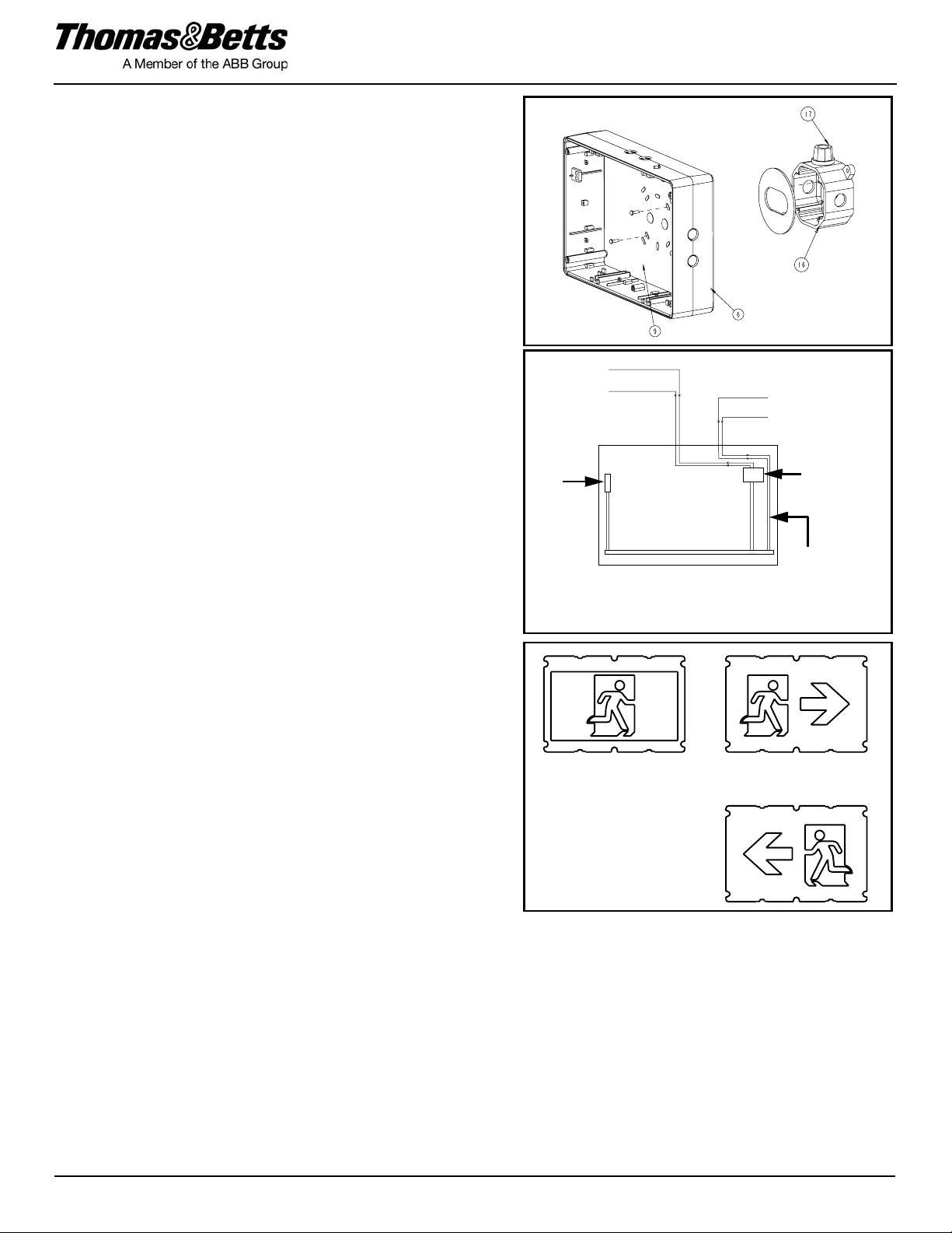
b. Remove the backplate (9) from the packaging. Determine the
proper knockouts to remove for mounting to the junction box (see
Figure 3).
c. Support area around knockouts with two blocks of wood. Strike
knockouts from the inside with a hammer and a screwdriver.
d. Reinstall the backplate to the frame using the 6 tamper-proof
screws (use the supplied bit).
2. Electrical connections: Connect one end to the leads inside the
enclosure and the other end to AC line voltage inside the junction
box. Connect the white lead to neutral and the purple lead to AC line
voltage (the input is universal ). (See Figure 4). Connect the
ground(green wire) to the junction box.
Optional: For AC models with DC remote power, one end connects
to the LED-STRIP leads inside theenclosure and the other endto the
DC input inside the junction box. Connect the redlead to the positive
and the blue lead to the negative of the remote DC input
(see Figure 4).
For ceiling mount: Mount the frame and junction box cover
assembly to junction box by using the provided securement screw.
For wall mount: Attach the frame (6) to the junction box, using the
junction box supplied screws. Install 2 stem washers to ensure
bonding.
3. Select the desired pictogram panel and install it with the opal diffuser
behind. The pictogram panel without arrow shall be installed facing
right (see Figure 5).
4. Install the lens by using the 6 tamper-proof screws.The o-ring has to
be installed on the center screws between the lens and the frame as
shown in figure 1.
The tamper-proof screws should be equally torqued to
approximately 10 - 15 in-lbs (1.1 - 1.7 N-m).
5. Energize AC. Sign will illuminate.
Figure 3
Figure 4
(Diagnostic models)
Purple- AC
White - Neutral Red + DC
Blue - DC
Battery
(Self-Powered
Transformer
DC wires for remote
DC supply
(Ac/DC models only)
only)
Primary wire connections must be isolated from charger.
Figure 5
pictogram panel with arrow
pictogram panel
Install the panel with Flip the panel
the person going to the right for arrow left (below)
Tel: (888) 552-6467 Fax: (800) 316-4515 www.tnb.com
Pictogram Sign for Hazardous Locations
3/4
02/15 750.1593 Rev. B
Manual Testing (Self-Powered Models)
Operate the magnetic “test switch” by holding the provided magnet
underneath the unit where indicated on the frame. The AC pilot lamp will
go out, the legend will flicker, but remain lit. Remove the magnet. The
AC pilot light will turn on, the legend will flicker but remain lit.
Automatic testing and diagnostics
A built in micro-controller will self-test the unitand identify displayfailures
of the uniton a monthly basis andidentifies as wellas displays failuresof
the electrical components: battery, battery charger and LEDs.
Self-test
The self-test is performed every 30 days for 1 minute, every 6
months for 30 minutes, and annually for 90 minutes.
Diagnostic function
The diagnostic function uses a bi-color pilot LED indicator. Service is
required if the LED turns red indicating that an alarm condition is
detected (see Figure 6).
Maintenance (All Models)
None required. For battery-operated units: if AC supply to the unit is to
be disconnected for 2 months or more, the battery must be
disconnected.
Note(Nickel-Cadmium) batteries are shipped discharged and may
require 10 minutes of connection to AC supply before start-up test
procedure, and 96 hours to reach full charge.
o Green Steady On AC On
-o Green One Blink In Test
o Red Steady On Battery Disconnect
-o Red One Blink Battery Failure
o-o Red Two Blinks Charger Failure
o-o-o-o Red Four Blinks LED Strip Failure
Figure 6
Diagnostic
indicator
AC Pilot light/
Tel: (888) 552-6467 Fax: (800) 316-4515 www.tnb.com
Pictogram Sign for Hazardous Locations
4/4
02/15 750.1593 Rev. B
Double Face Installation
Conversion from single-face to double-face sign.
1. Turn off AC power.
2. Remove backplate by unscrewing the six tamper-proof screws
holding the backplate to the frame (see Figure 7).
3. Install the four backpanel retention screws (see Figure 8).
Note: The four screws may already be installed.
4. Select the desired pictogram panel and install it with the opal diffuser
behind. The pictogram panel without arrow shall be installed facing
right (see Figure 5). Snap the top edges under the two top retention
screws and then snap the bottom edges under the two bottom
retention screws (see Figure 9).
5. Install the lens by using the 6 tamper-proof screws.The o-ring has to
be installed on the center screws between the lens and the frame as
shown in figure 10.
The tamper-proof screws should be equally torqued to
approximately 10 - 15 in-lbs (1.1 - 1.7 N-m).
6. Energize AC. Sign will illuminate.
WARNING:
Risk of Shock.
Disconnect Power before Installation.
Figure 7
Backplate
screws
tamper-proof
*Note: O-rings outside
.
Figure 8
Backpanel retention
screws
Figure 9
Snap opal panel
and pictogram panel
under these
screws.
Figure 10
*Note: O-rings inside
.
*
*

This manual suits for next models

1

Other ABB Safety Equipment manuals

ABB jokab safety Smile 11EA Tina User manual

ABB

ABB jokab safety Smile 11EA Tina User manual

ABB RD344 User manual

ABB

ABB RD344 User manual

ABB Stanilite Exit LED edgelit Quickfit User manual

ABB

ABB Stanilite Exit LED edgelit Quickfit User manual

ABB Welcome User manual

ABB

ABB Welcome User manual

ABB Nexus RF User manual

ABB

ABB Nexus RF User manual

ABB Tina 1A User manual

ABB

ABB Tina 1A User manual

ABB XT230RS/DALI Manual

ABB

ABB XT230RS/DALI Manual

ABB Stanilite Platinum exit LED Quickfit User manual

ABB

ABB Stanilite Platinum exit LED Quickfit User manual

ABB Jokab Safety Safeball JSTD1 User manual

ABB

ABB Jokab Safety Safeball JSTD1 User manual

ABB INCA 1EC Tina User manual

ABB

ABB INCA 1EC Tina User manual

ABB SafeMove2 Instructions for use

ABB

ABB SafeMove2 Instructions for use

ABB XT230H/DALI Manual

ABB

ABB XT230H/DALI Manual

ABB Stanilite Spitfire Standard User manual

ABB

ABB Stanilite Spitfire Standard User manual

ABB HD5-S User manual

ABB

ABB HD5-S User manual

ABB Stanilite Platinum Spitfire LED weatherproof User manual

ABB

ABB Stanilite Platinum Spitfire LED weatherproof User manual

ABB JSM D23C User manual

ABB

ABB JSM D23C User manual

ABB PrimEvo XT100E Manual

ABB

ABB PrimEvo XT100E Manual

Popular Safety Equipment manuals by other brands

MS3C MS3C-300TSB manual

MS3C

MS3C MS3C-300TSB manual

KAPPLER Zytron User information

KAPPLER

KAPPLER Zytron User information

BUCKINGHAM MFG BuckSqueeze 483 Series Instructions & warnings

BUCKINGHAM MFG

BUCKINGHAM MFG BuckSqueeze 483 Series Instructions & warnings

CAMP BLIN KIT manual

CAMP

CAMP BLIN KIT manual

Thomashilfen Octopus Assembly and instructions for use

Thomashilfen

Thomashilfen Octopus Assembly and instructions for use

Petzl PITAGOR manual

Petzl

Petzl PITAGOR manual

OCENCO M-20.2 Instruction booklet

OCENCO

OCENCO M-20.2 Instruction booklet

J4C BSR KIT J4C 20 Assembly instructions

J4C

J4C BSR KIT J4C 20 Assembly instructions

LAHTI PRO L4051001 User instructions

LAHTI PRO

LAHTI PRO L4051001 User instructions

DELTA PLUS FREEWAY HV User instructions

DELTA PLUS

DELTA PLUS FREEWAY HV User instructions

EDELRID BICOLOR manual

EDELRID

EDELRID BICOLOR manual

FrontLine RORS01 instruction manual

FrontLine

FrontLine RORS01 instruction manual

STI STI-7554 instruction manual

STI

STI STI-7554 instruction manual

Omron F3SP-U1P-TGR user manual

Omron

Omron F3SP-U1P-TGR user manual

Spinlock deckware Series manual

Spinlock

Spinlock deckware Series manual

Singing rock W2001 quick start guide

Singing rock

Singing rock W2001 quick start guide

Guardian Non-Shock Lanyard instruction manual

Guardian

Guardian Non-Shock Lanyard instruction manual

TOOLCRAFT 1435431 operating instructions

TOOLCRAFT

TOOLCRAFT 1435431 operating instructions

manuals.online logo
manuals.online logoBrands
  • About & Mission
  • Contact us
  • Privacy Policy
  • Terms and Conditions

Copyright 2025 Manuals.Online. All Rights Reserved.