Standfast TRAM TR-6-ST Series User manual

SEC
STAL
SEC
STAL
SEC
STAL
COMMITMENT
SECURITY
SECURITY
ANCHO
STALWARTNESS DURABLE
SUPPORT
STAY
REINFORCE
STALWARTNE
COMMITMENT
SECURITY
SECURITY
RELIABLE
FASTENER
GRIP
ANCHOR
ANCHOR
STALWARTNESS DURABLE
STRENGTH
POWER
SUPPORT
STAY
REINFORCE
STAY
STALWARTNESS
COMM
SECURITY
SE
RELIA
FAST
GRIP
AN
ANCHOR
STALWARTNESS
ST
SUPPO
STAY
R
COMMITMENT
SECURITY
SECURITY
RELIABLE
FASTENER
GRIP
ANCHO
ANCHOR
STALWARTNESS DURABLE
STRENGTH
POWER
SUPPORT
STAY
REINFORCE
STAY
STALWARTNE
COMMITMENT
SECURITY
SECURITY
RELIABLE
FASTENER
GRIP
ANCHOR
ANCHOR
STALWARTNESS DURABLE
STRENGTH
POWER
SUPPORT
STAY
REINFORCE
STAY
STALWARTNESS
COMM
SECURITY
SE
RELIA
FAST
GRIP
AN
ANCHOR
STALWARTNESS
ST
SUPPO
STAY
R
RELIABLE
FASTENER
GRIP
ANCHOR
STRENGTH
POWER
STAY
SECURI
STALWARTNES
SU
SECURI
G
STALWARTNES
SU
SECURI
G
STALWARTNES
SU
G
COMMITMENT
CURITY
SECURITY
ANCHOR
WARTNESS DURABLE
SUPPORT
STAY
REINFORCE
STALWARTNESS
COMMITMENT
RITY
SECURITY
RELIABLE
FASTENER
GRIP
ANCHOR
ANCHOR
SS DURABLE
STRENGTH
POWER
UPPORT
STAY
REINFORCE
STAY
STALWARTNESS
COMMITMENT
SECURITY
SECURITY
RELIABLE
FASTENER
GRIP
ANCHOR
ANCHOR
STALWARTNESS DURABLE
STRENGTH
POWER
SUPPORT
STAY
REINFORCE
STAY
STALWARTNESS
COMMITMENT
CURITY
SECURITY
RELIABLE
FASTENER
GRIP
ANCHOR
ANCHOR
WARTNESS DURABLE
STRENGTH
POWER
SUPPORT
STAY
REINFORCE
STAY
STALWARTNESS
COMMITMENT
RITY
SECURITY
RELIABLE
FASTENER
GRIP
ANCHOR
ANCHOR
SS DURABLE
STRENGTH
POWER
UPPORT
STAY
REINFORCE
STAY
STALWARTNESS
COMMITMENT
SECURITY
SECURITY
RELIABLE
FASTENER
GRIP
ANCHOR
ANCHOR
STALWARTNESS DURABLE
STRENGTH
POWER
SUPPORT
STAY
REINFORCE
STAY
STALWARTNESS
RELIABLE
FASTENER
GRIP
ANCHOR
STRENGTH
POWER
STAY
COMMITMENT
SECURITY
SECURITY
RELIABLE
ANCHOR
STALWARTNESS DURABLE
SUPPORT
STAY
REINFORCE
STAY
STALWARTNESS
COMMITMENT
SECURITY
SECURITY
RELIABLE
FASTENER
GRIP
ANCHOR
ANCHOR
STALWARTNESS DURABLE
STRENGTH
POWER
SUPPORT
STAY
REINFORCE
STAY
STALWARTNESS
COMMITMENT
SECURITY
SECURITY
RELIABLE
FASTENER
GRIP
ANCHOR
ANCHOR
STALWARTNESS DURABLE
STRENGTH
POWER
SUPPORT
STAY
REINFORCE
STAY
STALWARTNESS
FASTENER
GRIP
ANCHOR
STRENGTH
POWER
STAY
NT
TY
ER
OR
BLE
H
CE
TAY
NESS
NT
TY
ER
OR
BLE
H
CE
TAY
NESS
NT
TY
ER
OR
BLE
H
CE
TAY
NESS
MITMENT
CURITY
BLE
CHOR
DURABLE
RT
EINFORCE
STAY
TALWARTNESS
MITMENT
CURITY
BLE
TENER
CHOR
DURABLE
RENGTH
POWER
RT
EINFORCE
STAY
TALWARTNESS
MITMENT
CURITY
BLE
TENER
CHOR
DURABLE
RENGTH
POWER
RT
EINFORCE
STAY
TALWARTNESS
TENER
RENGTH
POWER
STAY
traMTM safety system
Technical manual
TR-6-ST Series – Standard TRAM
TR-6-RAT Series – Rotating Arm TRAM

Standfast Corporation Pty Ltd
ABN 49 108 256 917
PO Box 1224 Milton BC
Queensland 4064 Australia
Telephone +61 7 3369 9800
Facsimile +61 7 3369 9844
Email [email protected]
Website www.standfastcorp.com
DISCLAIMER AND COPYRIGHT NOTICE
1. The purpose of this Manual is to provide information about the Standfast TRAM Safety
System. It is not exhaustive in its coverage of rights or obligations nor is it legal advice.
2. This Manual has no legal status or legal effect whatsoever. Any reference to systems to
prevent falls is for guidance only. Readers of this Manual should seek appropriate guidance
from the appropriate Regulatory Authority as well as obtain appropriate legal advice in respect
of the application of the legislation and regulation in respect of the safety system.
3. This Manual may be affected by changes to Legislation or Regulation. Standfast
Enterprises Pty Ltd and Standfast Corporation Pty Ltd (Standfast) accepts no responsibility
for the accuracy, completeness or currency of the material included in this Manual.
4. Users of this Manual are encouraged to obtain professional advice on the relevant
Legislation and Regulations and to exercise their own skill and care in relation to any
material contained in this Manual.
5. Standfast disclaims any and all liability or responsibility for any loss or damages arising
out any use, or reliance on, this Manual.
6. This Manual is copyright. You may use and reproduce this material in an unaltered form
only for your personal non-commercial use or non-commercial use within your organisation.
Apart from any use permitted under the Copyright Act 1968, all other rights are reser ved.
Requests for other types of use should be directed to Standfast.
7. TRAM is a trademark of Standfast Enterprises Pty Ltd.
2TRAM SAFETY SYSTEM TECHNICAL MANUAL

1 READING THE DOCUMENTATION
1.1 LITERATURE INFORMATION
This manual contains safety information and instructions for operation and maintenance of
the Standfast TRAM System. This Manual should be stored in an area where it is accessible
to those responsible for maintenance of the equipment.
The information, specifications, and illustrations in this publication are provided on the basis of
information available at the time of writing. Continued improvement and advancement of product
design may have caused changes to your TRAM System, which are not included in this Manual.
Some photographs or illustrations in this Manual show details or attachments that may be
different from your TRAM system:
• Subassemblies, guards or covers may have been removed for illustrative purposes.
• The specifications, torques, pressures, measurements, adjustments, illustrations, and
other items can change at any time.
Important! These changes can affect the ser vice given to the product.
Whenever a question arises regarding your TRAM System or this Manual, and before starting
any job, please consult your Standfast TRAM dealer to obtain the complete and most current
information available.
1.2 ALERTS USED IN THIS MANUAL
Please read the list below of alerts used in this manual. These alerts are used to indicate
important instructions. Be sure to obey these instructions.
TRAM SAFETY SYSTEM TECHNICAL MANUAL 3
ALERT MEANING
Indicates a warning concerning an operation or hazard that
may lead to death or injury to persons if not per formed
correctly or with due care. Always pay attention to these warnings.
Indicates a restriction or important information.
Important! Be certain to read these items to avoid improper
use or damage to the equipment.
Note! Indicates additional information or explanation.
Be certain to read these items. WEIGHT

2 IMPORTANT SAFETY INFORMATION
2.1 GENERAL
The purpose of the TRAM Safety System is to protect the user from a fall from height. If the
system is not properly used, maintained or repaired, it may no longer protect against a fall
from height.
Failure to follow the instructions or heed the warnings contained in this manual could result
in injury or death. Improper operation, maintenance or repair of this product can be dangerous
and could result in injury or death.
All inspection, maintenance, servicing and repair work on the TRAM System shall be
carried out by a Competent Person.
A Competent Person is defined as a person:
• who is knowledgeable of recommendations and instructions on the TRAM System
issued by Standfast (including information contained in this manual)
• who is authorised* by Standfast to carry out inspection, maintenance, servicing and
repair work,
• who has the necessary training, skills and tools to per form the work properly,
• who is capable of identifying existing and predictable defects and hazards in any
component of the TRAM safety system and related equipment used in the work
environment,
• who is authorised to take prompt corrective action to eliminate or control hazards,
and has the skills and resources to do so,
• who is familiar with relevant guidelines and national and international safety
regulations.
*Your Standfast TRAM Dealer is authorised to carry out all inspection, maintenance,
servicing and repair work on the TRAM System. Your Standfast TRAM Dealer may also
be contacted to authorise a Competent Person.
All work must comply with the safety regulations of the jurisdiction in which the TRAM System
is installed and operated, including industry Codes of Practice and Standards.
No one should make any alterations or additions to the equipment. Any repair shall only be
carried out in accordance with authorized procedures.
The TRAM shall not be used outside its limitations as described in this Manual, or for any
purpose other than that for which it is intended.
Most accidents involving product operation, maintenance and repair are caused by failure to
observe basic safety rules or precautions. An accident can often be avoided by recognizing
potentially hazardous situations before an accident occurs.
Standfast Corporation cannot anticipate every possible circumstance that might involve a
potential hazard. The warnings in this publication and on the product are therefore not all
inclusive. If a tool, procedure, work method or operating technique not specifically
recommended by Standfast Corporation is used, you must satisfy yourself that it is safe for
you and others. You should also ensure that the product will not be damaged or made unsafe
by the operation, lubrication, maintenance or repair procedures you choose.
4TRAM SAFETY SYSTEM TECHNICAL MANUAL

2.2 SAFETY SIGNS AND LABELS
Safety precautions and warnings are provided in this manual and on the product. If these hazard
warnings are not heeded the product may not protect you or others from bodily injury or death.
The TRAM system is permanently marked or labelled to indicate its purpose, correct use,
limitations and other relevant information aimed at reducing the incidence or misuse or
misfitting of the equipment.
Make sure that all safety signs can be read. Clean or replace these if illegible. When cleaning the
labels use a cloth, water and soap. Do not use solvents, gasoline, etc to clean safety signs.
Contact your Standfast TRAM Dealer to organise replacement signs and labels.
2.3 SAFE WORKING AT HEIGHTS
The operation and maintenance of the TRAM must comply with the safety Legislation and
Regulations of the jurisdiction in which it is used.
Users of the TRAM System must be properly trained and competent. Further enquiries
regarding training materials and courses should be directed to your Standfast TRAM Dealer or
The TRAM restraint belt must only be used when the TRAM system is used as a total restraint
system. The TRAM restraint belt must not be used if there is a risk of free fall.
Total restraint means that there is no risk of fall as the user is prevented from reaching a fall
edge. This is achieved through combination of anchor point and lanyard length.
2.4 FALL ARREST
It is essential for safety that if the TRAM System is used as a fall-arrest system a full body
harness and energy absorber should be used.
The TRAM Belt described in this Manual is for use in total restraint and must NOT be used
in fall arrest.
In fall arrest applications, the TRAM System should always be positioned, and the work carried
out in such a way, as to minimise both the potential for falls and potential fall distance.
When the TRAM system is used as a fall-arrest system consideration should be given as to
how any necessary rescue could be safely achieved.
The operator should ensure that when the TRAM is used as a fall-arrest system that the
distance required or necessary to arrest the fall of a falling worker does not exceed the
distance available on site.
If the TRAM has been used to arrest a fall it should be not used again until confirmed in writing
by a competent person that it is acceptable to do so.
TRAM SAFETY SYSTEM TECHNICAL MANUAL 5

2.5 PRE-USE CHECK
Users must carry out a Pre-Use Check of the equipment, as per the instructions in this
Manual, to ensure that it is in a serviceable condition and operates correctly before use.
It is essential for safety that equipment is withdrawn from use immediately should any doubt
arise about its condition for safe use.
2.6 SERVICING
Servicing should be carried out at regular intervals as described in this Manual.
Services should only be conducted by a Competent Person and strictly in accordance with
servicing procedures.
Equipment Records of Periodic and Overhaul Services must be maintained and be available
to the user.
2.7 INSTALLATION
Anyone installing the TRAM system must read, understand and strictly adhere to the
instructions and safety information in this manual and any Installation Instructions for the
TRAM Safety system.
The installer must verify the adequacy of anchor point(s) either by calculation or by carrying
out a test in a sample of the material in compliance with the specifications of the appropriate
Standards.
2.8 MAINTENANCE & REPAIR
Attach a DO NOT OPERATE or similar warning tag to start switch or controls before per forming
maintenance or repairing the TRAM, if it is a vehicular installation. When appropriate, attach
tags at the engine and at each user’s position and disconnect starting controls. Ensure any
protective locks, controls or inhibitors are in the applied position before commencing work.
Some installations will require the use of fall protection equipment during removal and
installation of the TRAM system. A service platform or walkway is recommended.
It is the responsibility of the owner to ensure that access is achieved in accordance with local
regulations and standards.
Wear a hard hat, protective glasses, hearing protection, gloves and other protective equipment
as required by job conditions.
Do not wear loose clothing or jewellery that can catch on controls or other parts of the TRAM.
Use caution when removing springs. Gradually loosen (do not remove) the last bolts or nuts
located at opposite ends of any spring energy device, until all elastic energy is dissipated,
before completely removing the fasteners.
Do not carry out hot work on the TRAM device without first consulting your Standfast TRAM
Dealer. Your TRAM contains plastic components that may not function correctly in the event
that hot work is carried out on the TRAM.
6TRAM SAFETY SYSTEM TECHNICAL MANUAL

Compressed air can cause personal injury. When using compressed air for cleaning, wear a
protective face shield, protective clothing and protective shoes. The maximum air pressure
must be below 200 kPa (30 psi) for cleaning purposes.
Wear eye protection at all times when cleaning the TRAM system with hot and/or pressurised
water. Pressurised water could cause debris and/or hot water to be blown at the worker and
result in personal injury.
Escaping fluid under pressure, even a pin-hole size leak, can penetrate body tissue, causing
serious injury or possible death. It fluid is injected into your skin, it must be treated by a doctor
familiar with this type of injury immediately.
The TRAM System and replacement parts (brake pads) shipped from the factory are
asbestos free.
Support equipment and attachments correctly when working beneath them.
Do not allow unauthorized personnel on or around the TRAM when it is being serviced.
Do not attempt repairs you do not understand.
TRAM SAFETY SYSTEM TECHNICAL MANUAL 7

3 CONTENTS
1 Reading the documentation 3
1.1 Literature Information 3
1.2 Alerts used in this Manual 3
2 Important Safety Information 4
2.1 General 4
2.2 Safety Signs and Labels 5
2.3 Safe Working at Heights 5
2.4 Fall Arrest 5
2.5 Pre-Use Check 6
2.6 Servicing 6
2.7 Installation 6
2.8 Maintenance & Repair 6
3 Contents 8
4 Introduction 10
4.1 TRAM System Description 10
4.2 Safety 11
4.3 Compliance to Workplace Safety Laws 11
4.4 Customer Service 11
5 Description of Equipment 12
5.1 Features & Controls 12
5.2 TRAM Device Identification Plate 15
5.3 TRAM Belt Label 16
5.4 TRAM Installation Plate 17
6 Operation 18
6.1 General Operation 18
6.2 Operating the Rotary Joint (TR-6-RAT Series only) 22
6.3 Operating the Brake Override 22
7 Inspection & Maintenance 23
7.1 Inspection & Maintenance Activities & Schedule 23
7.2 Maintenance Records 25
8 TRAM Cleaning Procedures 26
8.1 TRAM Belt Cleaning Procedure 26
8.2 TRAM Device Cleaning Procedure 26
8.3 TRAM Installation Cleaning Procedure 27
9 Servicing Instructions 28
9.1 Fastener Torque Settings 29
9.2 Threadlocking Adhesive 29
9.3 Servicing the TRAM Belt 29
9.3.1 Periodic Service – TRAM Belt 30
9.3.2 Overhaul Service – TRAM Belt 31
8TRAM SAFETY SYSTEM TECHNICAL MANUAL

9.4 Servicing the TRAM Arm 31
9.4.1 Periodic Service – TRAM Arm 31
9.4.2 Overhaul Service – TRAM Arm 33
9.4.3 Latch Pin Adjustment Procedure 35
9.5 Servicing the TRAM Trolley 39
9.5.1 Periodic Service – TRAM Trolley 39
9.5.2 Overhaul Service – TRAM Trolley 41
9.5.3 ‘Play’ in the TRAM Arm 41
9.5.4 Procedure: Adjustment of the TRAM Wheel Set 41
9.5.4.1 Adjustment of Wheel position 43
9.5.5 Procedure: Replacement of the TRAM Wheel Set 43
9.6 Servicing the TRAM Brake System 44
9.6.1 Periodic Service – TRAM Brake System 46
9.6.2 Overhaul Service – TRAM Brake System 47
9.6.3 Brake Adjustment Procedure 48
9.6.3.1 TYPE I Brake System Adjustment 49
9.6.3.2 TYPE II Brake System Adjustment 49
9.6.4 Procedure: Replacement of the TYPE I Brake Cable
with the TYPE II Brake Cable 50
9.6.5 Procedure: To Replace the TYPE II Brake Cable 57
9.7 Servicing the TRAM Installation 60
9.7.1 Periodic Service – TRAM Installation 60
9.7.2 Overhaul Service – TRAM Installation 61
10 Repairs to the TRAM System 62
10.1 Damage to the TRAM System 62
10.2 The Repair Process 62
10.3 Verification of Repairs 62
11 Replacement & Spare Parts 63
11.1 Ordering Parts 63
11.2 Spare Parts List 63
12 Recertification of the TRAM System 64
13 Guidelines for Installation of the TRAM System 65
14 Specifications 66
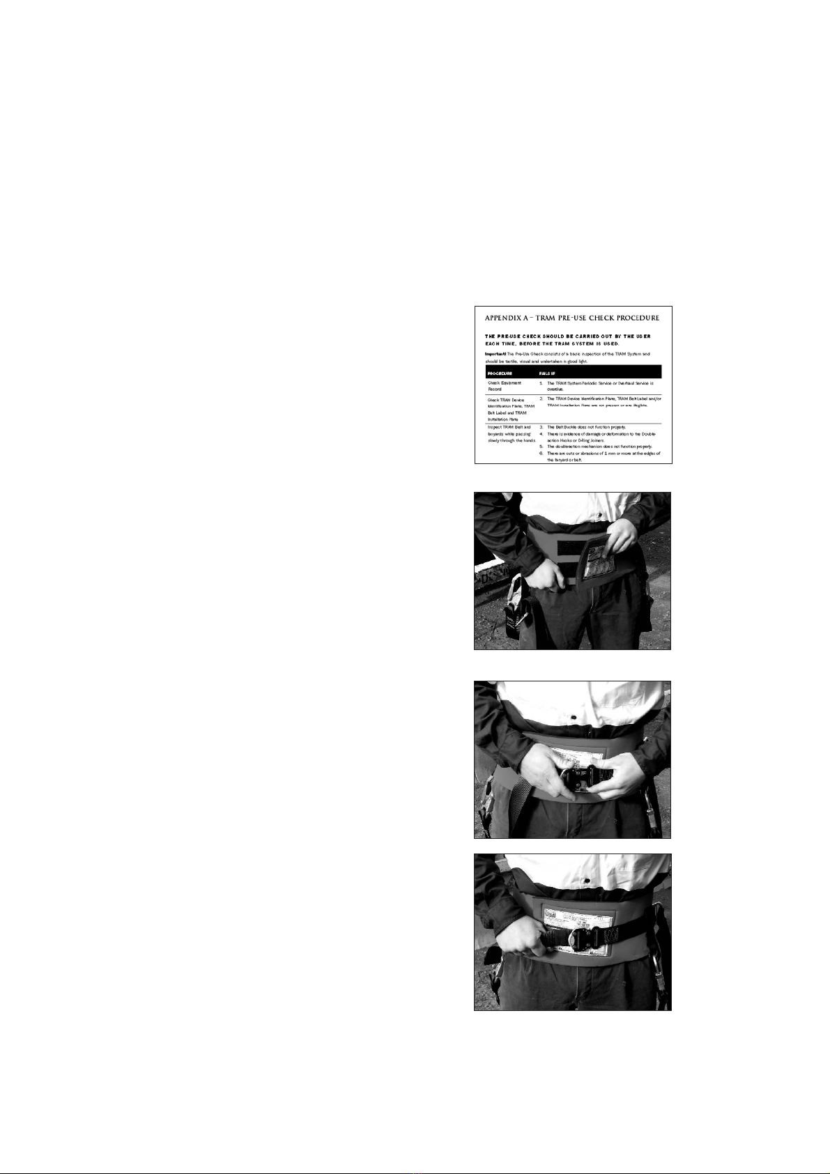
Appendix A TRAM Pre-Use Check Procedure 67
Appendix B TRAM Service Toolbox List 68
Appendix C Equipment Record 69
TRAM SAFETY SYSTEM TECHNICAL MANUAL 9
4 INTRODUCTION
4.1 TRAM SYSTEM DESCRIPTION
The TRAM Safety System described in this publication is a total restraint height safety system.
It is designed for various industrial, mining, defence, transport and domestic height safety
applications to provide the user with an ideal system of mobility, stability and restraint.
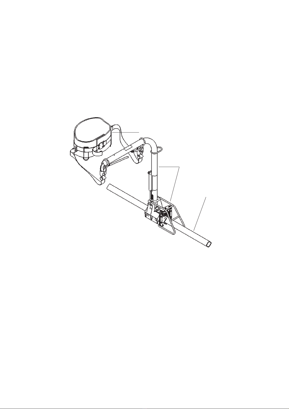
The TRAM (Safety) System consists of three components; the TRAM, the TRAM Belt and the
TRAM Installation.
Figure 4.1 The TRAM Safety System
The TRAM (or TRAM device) is a mobile anchor point that moves along the fixed rail.
For inspection, maintenance and repair purposes, the TRAM is classified into three
subassemblies – the TRAM Arm, the TRAM Trolley and the TRAM Brake System.
The TRAM Belt is a restraint belt that is worn by the user and attached to the TRAM by
two lanyards.
The TRAM Installation consists of the fixed rail and the mounting hardware which attaches
the fixed rail to the structure or vehicle to which the TRAM System is fitted.
10 TRAM SAFETY SYSTEM TECHNICAL MANUAL
TRAM Belt
TRAM
TRAM Installation

4.2 SAFETY
The “Important Safety Information” section lists basic safety precautions. In addition, this
section identifies hazardous situations, which are identified within the text by the highlighted
warning symbol. Read and understand the basic precautions listed in the “Important Safety
Information” section before using or performing maintenance or repair of this product.
4.3 COMPLIANCE TO WORKPLACE SAFETY LAWS
The use and maintenance of the TRAM Safety System must comply with the Workplace Safety
Legislation and Regulations of the jurisdiction in which the TRAM System is used.
The TRAM and the TRAM Rail have been tested to the specifications of, and are compliant with:
EN 795:1997 Protection against falls from a height – Anchor devices – Requirements and
testing (Class D anchor device employing a horizontal rigid anchor rail)
The TRAM Belt has been tested to and is compliant with:
EN 358:2000 Personal protective equipment for work positioning and prevention of falls
from a height – Belts for work positioning and restraint and work positioning lanyards
(Waist belt intended for restraint)
4.4 CUSTOMER SERVICE
Your satisfaction is a primary concern to Standfast Corporation and its dealers. When a
problem arises concerning the sale, operation or service of your TRAM System, please contact
the Standfast TRAM Dealer in your area.
The Standfast TRAM Dealer nearest to you can be located by consulting the website:
www.standfastcorp.com.
Standfast Corporation may be contacted directly by email or phone by consulting the website:
www.standfastcorp.com, or in writing to:
The Customer Service Manager
Standfast Corporation
PO Box 1224,
Milton BC, Queensland
Australia, 4064
TRAM SAFETY SYSTEM TECHNICAL MANUAL 11

5 DESCRIPTION OF EQUIPMENT
This chapter provides the names and location of major components of the TRAM Safety
System, and also describes their functions.
5.1 FEATURES & CONTROLS
Refer to Figures 5.1 and 5.2 to identify the features and control components of the TRAM
System. Figure 5.1 illustrates a TRAM in the TR-6-ST Series of products and is also termed
the “Standard TRAM”. Figure 5.2 illustrates the TR-6-RAT Series of products and consists of
a Standard TRAM with a rotary joint incorporated into the TRAM Arm. This type of TRAM is
termed the Rotating Arm TRAM.
Figure 5.1 Features and Controls of the TRAM System – TR-6-ST Series
Figure 5.2 Features and Controls of the TRAM System (with Rotary Joint fitted) – TR-6-RAT Series
12 TRAM SAFETY SYSTEM TECHNICAL MANUAL
Attachment Ring
TRAM Belt
Rail
Lanyard
Clutch Lever
Brake Lever
Attachment Ring
Arm
Brake Override
Double-action Hooks
Attachment Ring
TRAM Belt
Rail
Lanyard
Clutch Lever
Brake Lever
Attachment Ring
Arm
Brake Override
Double-action Hooks
Rotary Joint Lever
Rotary Joint
Arm
The TRAM Arm provides a handhold that moves with the user and also supports the
Attachment Rings which are anchor points for the restraint belt. A Rotary Joint is fitted to the
TRAM Arm as part of the TR-6-RAT Series.
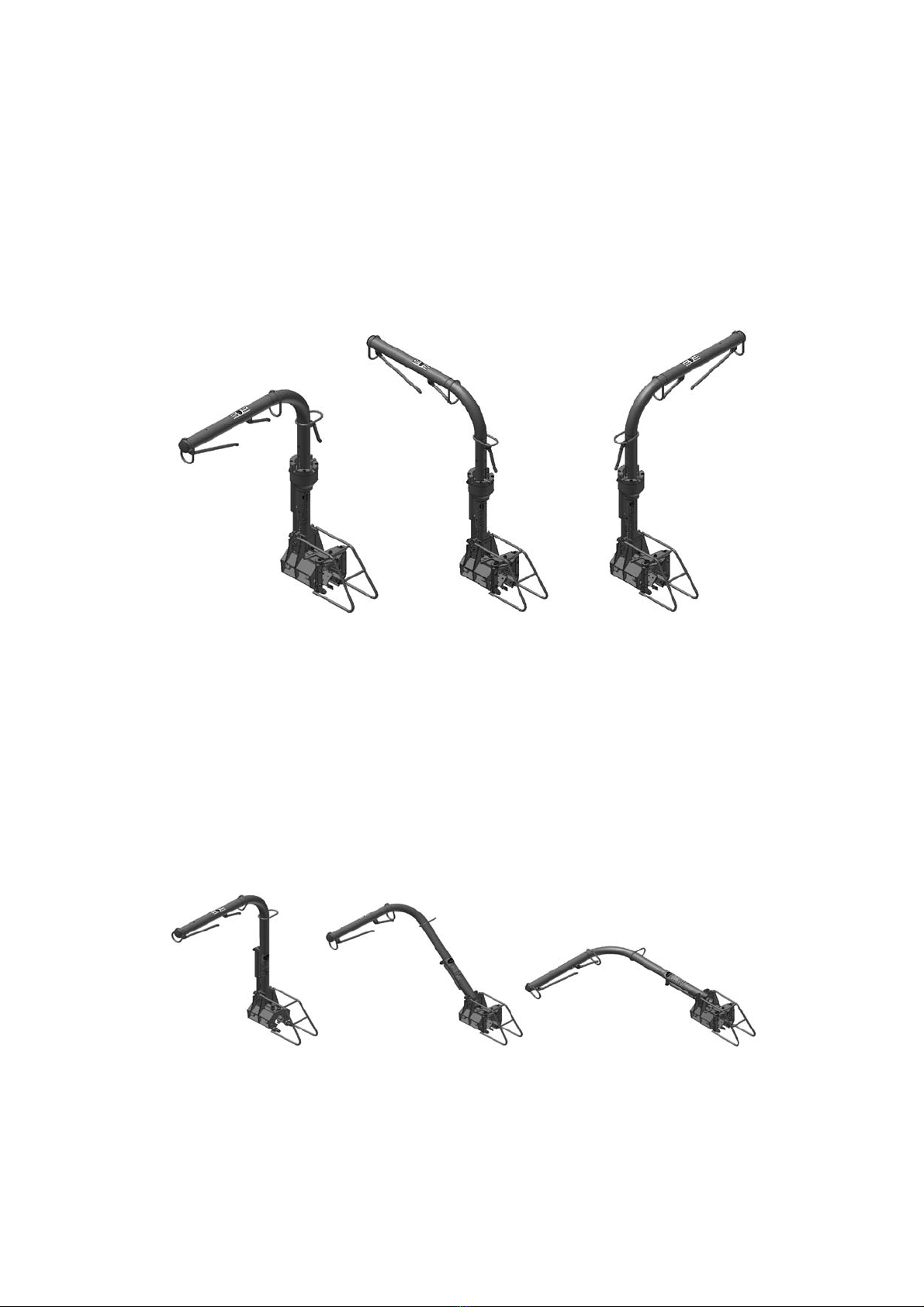
Rotary Joint (TR-6-RAT Series ONLY)
The Rotary Joint allows the horizontal segment of the Arm to rotate relative to the TRAM
Device. By activating the Rotary Joint Lever, the Arm can be rotated through 180 degrees,
in 90 degree increments. This is illustrated in Figure 5.3.
Figure 5.3 TRAM Arm Positions with Rotar y Joint fitted (TR-6-RAT Series ONLY)
Clutch Lever
The pivoting movement of the TRAM Arm is controlled by the Clutch lever. Activating the lever
allows the user to pivot the TRAM Arm between vertical and horizontal positions. The arm
position can be locked into either the horizontal, 45 degree or the vertical position and will
lock in place in position when the pivot clutch lever is released. See Figure 5.4.
Figure 5.4 TRAM Arm positions
TRAM SAFETY SYSTEM TECHNICAL MANUAL 13
O
o
Position 90
o
Position 180
o
Position

Brake Lever
In its normal position, the Brake system is locked and the TRAM Device is locked in its location
on the TRAM rail. Activating the Brake lever by hand releases the TRAM Device from its locked
position and allows it to move along the rail with the user. Releasing the Brake lever allows it to
return to the normal position and again lock the brake system and TRAM onto the rail.
Attachment Rings
Attachment Rings are anchor points provided on the TRAM Arm for attachment of the Lanyards
via the Double-action Hooks.
Double-action Hooks
The Double-action Hooks are attached to the end of the lanyards and are used to attach the
user to the TRAM Arm via the Attachment rings.
TRAM Belt
The TRAM Belt is a purpose designed restraint belt with two lanyards that attach to the TRAM
with double action hooks. The Belt is fixed around the user’s waist using a quick lock and
release buckle mechanism and must be fastened when the Belt is in use
The TRAM Belt is available in the following sizes:
TRAM Belt Sizes
WAIST SIZE TRAM BELT SIZE TRAM BELT COLOUR
Up to 70cm [27.5”] Small Purple
70-100cm [27.5-39.4”] Medium Red
100-125cm [39.4-49.2”] Large Blue
125-150cm [49.2-59.1”] Extra-Large Black
Lanyards
The lanyards are of fixed length and allow the user to move and work while attached to the
TRAM Arm.
Brake Override Foot Lever
In its normal position, the Brake system is locked and the TRAM Device is fixed in its
location on the TRAM rail. In the event that the Brake lever fails to function, the Brake
override foot-lever may be used to unlock the TRAM Device from its fixed location, allowing
it to move along the rail with the user.
Rail & Fixtures
The Rail provides a path for the TRAM Device to move along. Rail fixtures hold the rail in position
and are designed to comply with Design Strength requirements of legislation. Rail fixtures
provide the inter face between the Rail and the structure to which the TRAM is to be fixed.
14 TRAM SAFETY SYSTEM TECHNICAL MANUAL

5.2 TRAM DEVICE IDENTIFICATION PLATE
The TRAM (Device) is supplied with an identification plate as illustrated in Figure 5.2.1 below.
The plate is usually affixed to the lower section of the TRAM Arm. The plate contains important
information about the TRAM system including the type of TRAM Product, a unique serial
number, a date of manufacture and a statement of compliance to legislation.
The TRAM Identification plate is permanently attached to your TRAM system and should not
be removed or modified in any way.
The Installation Plate may vary in design and content subject to Workplace Safety Legislation
and Regulations of the jurisdiction in which the TRAM System is used
Figure 5.2.1 TRAM Identification Plate
TRAM SAFETY SYSTEM TECHNICAL MANUAL 15
Important!
Important!

5.3 TRAM BELT LABEL
The TRAM Belt is supplied with an information label sewn into the belt material and illustrated
in Figure 5.3.1 below. The label contains important information about the TRAM Belt including
a description of the product, product identification, serial number, date of manufacture and
date to be taken out of service, a statement of compliance to legislation and a pictogram.
The TRAM Belt label is permanently attached to your TRAM Belt and should not be removed
or modified in any way.
The Installation Plate may vary in design and content subject to Workplace Safety Legislation
and Regulations of the jurisdiction in which the TRAM System is used.
Figure 5.3.1 TRAM Belt Label
16 TRAM SAFETY SYSTEM TECHNICAL MANUAL
Important!
Important!

5.4 TRAM INSTALLATION PLATE
The TRAM Installation Plate is an information plate affixed in a visible location at the TRAM
Installation (the anchorage point). This plate should be clearly visible to the user before the
user is in a position to operate the TRAM System. The plate contains important information
about the TRAM Installation including the installer’s identification, the installation serial
number, the date of installation, a statement of compliance to legislation and a pictogram.
The TRAM Installation Plate is permanently attached to your TRAM Installation and should not
be removed or modified in any way.
The Installation Plate may vary in design and content subject to Workplace Safety Legislation
and Regulations of the jurisdiction in which the TRAM System is used.
Figure 5.4.1 TRAM Installation Plate
TRAM SAFETY SYSTEM TECHNICAL MANUAL 17
Important!
Important!
6 OPERATION
The instructions provided in section 6.1 should be used to operate the TR-6-ST Series and the
TR-6-RAT Series TRAM Systems. Section 6.2 applies to operation of the Rotary Joint supplied
with the TR-6-RAT Series TRAM System. Section 6.3 describes operation of the Brake Override.
6.1 GENERAL OPERATION
STEP 1
Perform a pre-use check in accordance with
the TRAM Pre-Use Check Procedure. (A copy
of the Pre-use check procedure is contained
in Appendix A.)
STEP 2
Put on the TRAM restraint belt.
STEP 3
Fasten the belt buckle.
Pull belt strap tight.
Note: The lanyards are kept in a ‘carry position’
hooked back to the belt.
Note: When worn correctly, the restraint belt should
look like the restraint belt in the illustration.
18 TRAM SAFETY SYSTEM TECHNICAL MANUAL
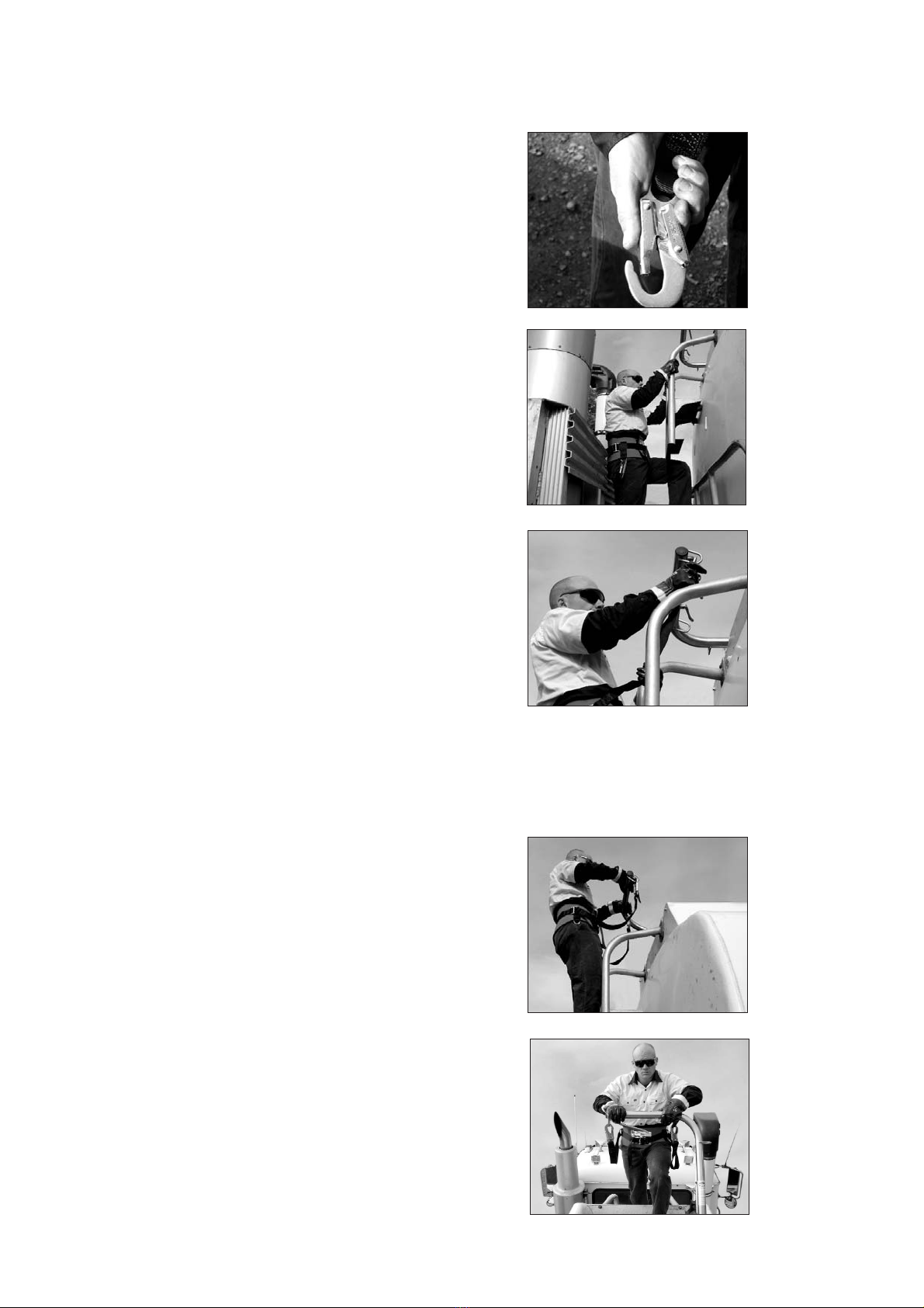
Note: Double action hooks are operated by first
depressing the latch on the back spine of the
hook and then opening the hook gate.
STEP 4
Move to the work area into a position where the
TRAM Arm can first be reached and held.
When climbing a ladder, three points of contact
should be maintained on the ladder at all times.
STEP 5
One-at-a-time, unclip the double-action hooks and
take the hooks from their ‘carry position’ on the
belt and attach them to the attachment rings on
the TRAM arm.
Do this one-at-a-time and maintain three points of
contact throughout.
Note: Once the double-action hooks are attached to
the attachment rings on the TRAM Arm, the user is
in a position of total restraint and can work safely.
STEP 6
Activate the clutch lever. The TRAM Arm will pivot
from the horizontal “lay down” position to its
vertical position. Whilst this takes place move
from the ladder onto the walkway.
Grip the Arm with both hands when activating the
clutch lever to maintain three points of contact
throughout the transition.
TRAM SAFETY SYSTEM TECHNICAL MANUAL 19
Important!
Important!
Important!

STEP 7
Once on top of the walkway, move the TRAM
arm along the rail by activating the brake lever.
You are in total restraint and can move safely
along the walkway.
Note: Whilst standing and walking the anchor
points are at waist level.
Note: Horizontal travel along the walkway is
controlled by the brake lever.
STEP 8
Once at the required work position, release the
brake lever to apply the brake and lock the TRAM
in position.
STEP 9
If the user needs to kneel, squat or sit, the TRAM
Arm and attachment points can be lowered by
pivoting the TRAM Arm. Pivot the TRAM Arm by
operating the clutch lever.
STEP 10
Once the required task is complete, activate the
brake lever and move back along the walkway.
The lanyards are of suitable length to allow the
user to turn around and walk back along the
walkway head first.
20 TRAM SAFETY SYSTEM TECHNICAL MANUAL
Important!
This manual suits for next models
1
Table of contents
Other Standfast Safety Equipment manuals

Popular Safety Equipment manuals by other brands


Survitec Group
Survitec Group Crewsaver Crewfit Twin 275N Service manual

E2S
E2S GNExCP6A-PB instruction manual

Milwaukee
Milwaukee HEAVY DUTY L4 HBLB Original instructions

Mittelmann
Mittelmann LiftEvac Instructions for Use/Test Book

Innotech
Innotech EAP-POINT-11 quick start guide

3M
3M DBI-SALA EZ-Line User instructions


