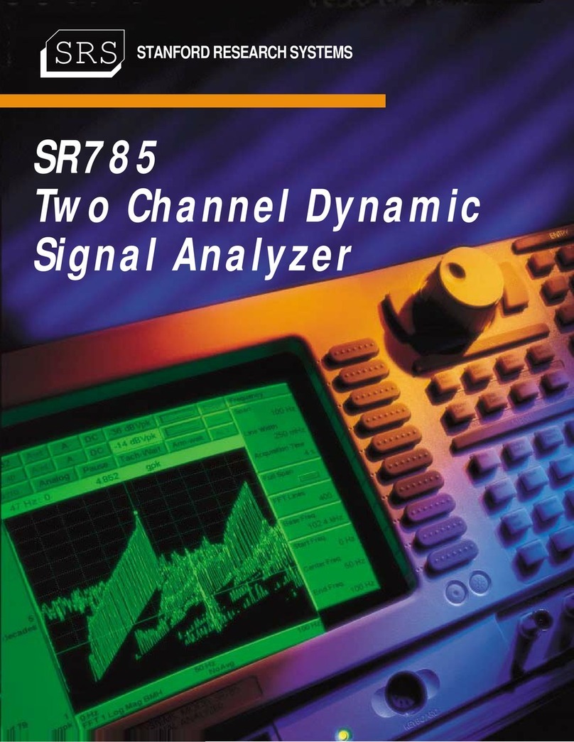
Stanford Research Systems SR785 User manual

Revision 1.4 (December, 2006)
Operating Manual and
Programming Reference
Model SR785
Dynamic Signal Analyzer
1290-D Reamwood Avenue
Sunnyvale, CA 94089 U.S.A.
Phone: (408) 744-9040 • Fax: (408) 744-9049
Copyright © 1995, 1996, 1998
Stanford Research Systems, Inc.
All Rights Reserved

Certification
Stanford Research Systems certifies that this product met its published specifications at the time
of shipment. Stanford Research Systems further certifies that its calibration measurements are
traceable to the United States National Institute of Standards and Technology (NIST).
Warranty
This Stanford Research Systems product is warranted against defects in materials and
workmanship for a period of one (1) year from the date of shipment.
Service
For warranty service or repair, this product must be returned to a Stanford Research Systems
authorized service facility. Contact Stanford Research Systems or an authorized representative
before returning this product for repair.
Information in this document is subject to change without notice.
Copyright © Stanford Research Systems, Inc., 1995, 1996, 1998. All rights reserved.
Stanford Research Systems, Inc.
1290-D Reamwood Avenue
Sunnyvale, California 94089
Printed in U.S.A.

i
SR785 Dynamic Signal Analyzer
Safety and Preparation For Use
WARNING!
Dangerous voltages, capable of causing injury or death, are
present in this instrument. Use extreme caution whenever the
instrument cover is removed. Do not remove the cover while
the unit is plugged into a live outlet.
Caution This instrument may be damaged if operated with the LINE VOLTAGE SELECTOR set
for the wrong AC line voltage or if the wrong fuse is installed.
Line Voltage Selection
The SR785 operates from a 100V, 120V, 220V, or 240V nominal AC power source
having a line frequency of 50 or 60 Hz. Before connecting the power cord to a power
source, verify that the LINE VOLTAGE SELECTOR card, located in the rear panel fuse
holder, is set so that the correct AC input voltage value is visible.
Conversion to other AC input voltages requires a change in the fuse holder voltage card
position and fuse value. Disconnect the power cord, open the fuse holder cover door and
rotate the fuse-pull lever to remove the fuse. Remove the small printed circuit board and
select the operating voltage by orienting the printed circuit board so that the desired
voltage is visible when pushed firmly into its slot. Rotate the fuse-pull lever back into its
normal position and insert the correct fuse into the fuse holder.
Line Fuse Verify that the correct line fuse is installed before connecting the line cord. For
100V/120V, use a 1.5 Amp fuse. For 220V/240V, use a 3/4 Amp fuse.
Line Cord The SR785 has a detachable, three-wire power cord for connection to the power source
and to a protective ground. The exposed metal parts of the instrument are connected to
the outlet ground to protect against electrical shock. Always use an outlet which has a
properly connected protective ground.
Service Do not attempt to service or adjust this instrument unless another person, capable of
providing first aid or resuscitation, is present.
Do not install substitute parts or perform any unauthorized modifications to this
instrument. Contact the factory for instructions on how to return the instrument for
authorized service and adjustment.
Fan The fans in the SR785 are required to maintain proper operation. Do not block the vents
in the chassis or the unit may not operate properly.

ii

iii
SR785 Dynamic Signal Analyzer
Contents
Safety and Preparation For Use i
Contents iii
Table of Figures vii
Features ix
Specifications xi
Chapter 1 Getting Started
General Installation 1-2
Front Panel Quick Start 1-3
Things To Watch Out For 1-5
Analyzing a Sine Wave 1-7
Measuring a Frequency Response Function 1-11
Linking (Advanced Operation) 1-15
Triggering and the Time Record 1-19
Octave Analysis 1-23
Capture 1-27
Waterfall Display 1-34
Swept Sine Measurement 1-41
Saving and Recalling 1-47
User Math Functions 1-52
Limit Testing 1-56
Exceedance Statistics 1-60
Chapter 2 Analyzer Basics
Measurement Groups 2-4
What is an FFT? 2-6
FFT Frequency Spans 2-8
FFT Time Record 2-10
FFT Windowing 2-12
FFT Measurements 2-16
Views 2-21
FFT Averaging 2-24
Real Time Bandwidth and Overlap 2-27
Waterfall Display 2-30
Capture Buffer 2-33
The Source 2-36
Correlation Analysis 2-38
Octave Analysis 2-41
Swept Sine Measurements 2-47
Order Analysis 2-55
Time/Histogram Measurements 2-58
Trace Storage 2-60
User Math Functions 2-61
Signal Inputs 2-65

iv Contents
Input Connections 2-68
Intrinsic Noise Sources 2-70
External Noise Sources 2-71
Curve Fitting and Synthesis 2-75
Chapter 3 Operation
Overview 3-3
Front Panel Connectors 3-6
Rear Panel Connectors 3-8
Screen Display 3-11
Status Indicators 3-18
Keypad 3-23
Normal and Alternate Keys 3-23
Menu Keys 3-24
Entry Keys 3-25
Control Keys 3-28
Function Keys 3-34
Macros 3-38
Chapter 4 Menus
Frequency Menus 4-7
FFT Frequency Menu 4-7
Octave Frequency Menu 4-12
Swept Sine Frequency Menu 4-15
Order Frequency Menu 4-19
Time/Histogram Frequency Menu 4-23
Display Setup Menu 4-25
Display Options Menu 4-46
Marker Menu 4-50
Normal Marker Menu 4-54
Harmonic Marker Menu 4-58
Sideband Marker Menu 4-61
Band Marker Menu 4-64
Frequency/Damping Marker Menu 4-66
Source Menus 4-67
Sine Source Menu 4-71
Chirp Source Menu 4-73
Noise Source Menu 4-75
Arbitrary Source Menu 4-78
Swept Sine Source Menu 4-83
Input Menu 4-87
Input Configuration Menu 4-89
Transducer Parameter Menu 4-92
Tachometer Input Menu 4-95
Playback Input Menu 4-97

Contents v
Trigger Menu 4-100
Average Menus 4-107
FFT, Correlation, and Order Average Menu 4-107
Octave Average Menu 4-115
Swept Sine Average Menu 4-119
User Math Menu 4-122
Window Menu 4-131
Waterfall Menu 4-135
Capture Menu 4-143
Analysis Menu 4-147
Data Table Analysis Menu 4-150
Limit Testing Analysis Menu 4-152
Marker Statistics Analysis Menu 4-156
Exceedance Statistics Analysis Menu 4-159
Curve Fit Menu 4-161
Disk Menu 4-167
Nodal Degree-of-Freedom Menu 4-171
Recall Settings Menu 4-174
Disk Buffers Menu 4-177
Disk Upkeep Menu 4-182
Output Menu 4-184
System Menu 4-191
System Remote Menu 4-194
System Preferences Menu 4-196
System Date/Time Menu 4-199
System Diagnostics Menu 4-200
Edit Macro Menu 4-203
Chapter 5 Programming
Index of Commands 5-2
Alphabetical List of Commands 5-12
Introduction 5-21
Command Syntax 5-25
Frequency Commands 5-28
Display Setup Commands 5-37
Display Options Commands 5-43
Marker Commands 5-45
Source Commands 5-53
Input Commands 5-60
Trigger Commands 5-66
Average Commands 5-68
User Math Commands 5-74
Window Commands 5-78
Waterfall Commands 5-80
Capture Commands 5-83

vi Contents
Memory Allocation Commands 5-84
Data Table Commands 5-85
Limit Test Commands 5-87
Marker Statistics Commands 5-89
Exceedance Statistics Commands 5-90
Disk Commands 5-94
Output Commands 5-97
System Commands 5-100
Front Panel Commands 5-102
Data Transfer Commands 5-107
Interface Commands 5-117
Nodal Degree-of-Freedom Commands 5-118
Status Reporting Commands 5-120
Status Word Definitions 5-124
Example Program 5-129
Chapter 6 File Conversion
Why File Conversion? 6-2
SR785 File Types 6-3
Supported External File Types 6-4
Using the File Conversion Utility 6-5

vii
SR785 Dynamic Signal Analyzer
Table of Figures
Figure 2-1 Waterfall Display 2-30
Figure 2-2 Transfer Functions 2-48
Figure 2-3 Capacitive Coupling 2-71
Figure 2-4 Inductive Coupling 2-72
Figure 2-5 Resistive Coupling 2-73
Figure 3-1 Front Panel 3-3
Figure 3-2 Rear Panel 3-8
Figure 3-3 Dual Display Screen 3-11
Figure 3-4 Overlay Display Screen 3-12
Figure 3-5 Vertical Scale Bar 3-13
Figure 3-6 Horizontal Scale Bar 3-14
Figure 3-7 Marker Region 3-15
Figure 3-8 Marker Position Bar 3-15
Figure 3-9 Status Indicator Panel 3-18
Figure 3-10 Front Panel Keypad 3-23

viii

ix
SR785 Dynamic Signal Analyzer
Features
Measurements FFT Group
FFT (Linear Spectrum) Time Record Windowed Time
Time Capture Frequency Response Power Spectrum
Cross Spectrum Coherence Orbit
User Math Functions
Correlation Group
Cross Correlation Autocorrelation Time Record
Windowed Time Time Capture User Math Functions
Octave Analysis Group
1/1, 1/3, 1/12 Octave Time Capture User Math Functions
LEQ Impulse
Swept Sine Group
Spectrum Transfer Function Cross Spectrum
Normalized Variance User Math Functions
Time Histogram Group
Histogram Probability Density Cumulative Density
Unfiltered Time RecordUser Math Functions Time Capture
Views Log Magnitude Linear Magnitude Magnitude Squared
Real Part Imaginary Part Phase
Unwrapped Phase Nichols Plot Nyquist Plot
Displays Single Dual Upper/Lower Front/Back
Waterfall with Skew Zoom and Pan
FFT Resolution 100, 200, 400 or 800 FFT lines
FFT Windows Hanning Blackman-Harris Flattop
Kaiser Uniform Force/Exponential
User defined
Correlation Windows [-T/2..T/2] [-T/4..T/4] [0..T/2]
Averaging RMS Vector Peak Hold
Linear or Exponential Preview Time Records Equal Confidence
Analysis Harmonic Sideband Band
Peak Finding THD/THD+N Limit Testing
Data Table Exceedance (LN) Statistics
Waterfall Slice Curve Fitting Curve Synthesis
User Math +, -, *, / Conjugate Magnitude/Phase
Real/Imaginary Sqrt FFT/Inverse FFT
jωLog/Exp d/dx
Group Delay A, B, C Wt

x Features
Source Outputs Sine Two Tone Swept Sine
Offset White/Pink Noise Burst Noise
Chirp Burst Chirp Arbitrary
Trigger Arming Auto Arm Manual Arm RPM Arm
Time Arm
Trigger Sources Continuous Internal External
External/TTL Source Manual
Time Capture Capture time data for later analysis (FFT or Octave). Up to 2 Msamples
of data can be saved with standard memory, 8 Msamples with optional
memory.
Storage 3.5”, 1.44 Mbytes, DOS formatted disk. Save data, setups and hardcopy.
Hard Copy Print to dot matrix or LaserJet/InkJet printers. Plot to HPGL or
Postscript plotters. Print/Plot on-line (serial, parallel or IEEE-488) or to
disk file. GIF, EPS and PCX graphic formats available for disk output.
File Translation Native SR785 binary files can be converted to: ASCII, MATLAB®
.MAT Files, Universal File Format, and HP SDF v3 Files.SDF and
SR780 files can be converted to native SR785 binary format.
Interfaces RS232 serial, Centronics parallel and IEEE-488.
Help On screen help system provides Operating Manual and Programming
Reference on-line.

xi
SR785 Dynamic Signal Analyzer
Specifications
Specifications apply after 30 minutes of warm-up and within 2
hours of last auto-offset. All specifications are with 400 line
FFT resolution and anti-alias filters enabled unless stated
otherwise.
Frequency
Range 102.4 kHz or 100 kHz (both displays have the same range).
FFT Spans 195.3 mHz to 102.4 kHz or 191 mHz to 100 kHz.
The 2 displays can have different spans and start
frequencies.
FFT Resolution 100, 200, 400 or 800 lines
Real Time Bandwidth 102.4 kHz (highest FFT span with continuous data
acquisition and averaging on both inputs).
Accuracy 25 ppm from 20°to 40°C
FFT Dynamic Range
Dynamic Range -90 dBfs typical, -80 dBfs guaranteed (FFT and Octave),
145 dB (Swept Sine).
Includes spurs, harmonic and intermodulation distortion and
alias products. Excludes alias responses at extremes of span.
Harmonic Distortion <-80 dB (Single tone in band).
Intermodulation Distortion <-80 dB (Two tones in band, each <- 6.02 dBfs).
Spurious <-80 dBfs
Alias Responses <-80 dBfs (Single tone outside of span, < 0 dBfs, < 1 Mhz).
Full Span FFT Noise Floor -100 dBfs typical (Input grounded, Input Range > -30 dBV,
Hanning window, 64 RMS averages).
Residual DC Response < -30 dBfs (FFT with Auto Cal On).
Amplitude Accuracy
Single Channel ± 0.2 dB (excluding windowing effects).
Cross Channel ± 0.05 dB (dc to 102.4 kHz)
(Transfer Function measurement, both inputs on the same
Input Range, RMS averaged).
Phase Accuracy
Single Channel ± 3.0 deg relative to External TTL trigger.
(-50 dBfs to 0 dBfs, freq < 10.24 kHz)
(Center of frequency bin, DC coupled)
For Uniform, Blackman-Harris, Hanning, Flattop
and Kaiser windows, phase is relative to a cosine
wave at the center of the time record.
For Force and Exponential windows, phase is relative
to a cosine wave at the beginning of the time record.
Cross Channel ± 0.5 deg (dc to 51.2 kHz)
± 1.0 deg (dc to 102.4 kHz)
(Transfer Function measurement, both inputs on the same
Input Range, Vector averaged.)

xii Specifications
Signal Inputs
Number of Inputs 2
Full Scale Input Range -50 dBV (3.16 mVpk) to +34 dBV (50 Vpk) in 2 dB steps.
Maximum Input Level 57 Vpk
Input Configuration Single-ended (A) or True Differential (A-B).
Input Impedance 1 MΩ+ 50 pF
Shield to Chassis Floating Mode: 1 MΩ + 0.01 µF
Grounded Mode: 50
Ω
Shields are always grounded in differential input (A-B).
Maximum Shield Voltage 4 Vpk
AC Coupling -3 dB rolloff at 0.16 Hz.
CMRR 90 dB at 1 kHz (Input Range < 0 dBV).
80 dB at 1 kHz (Input Range <10 dBV).
50 dB at 1 kHz (Input Range ≥10 dBV).
ICP Signal Conditioning Current Source: 4.8 mA
Open Circuit Voltage +26 V
A-weight Filter ANSI Standard S1.4-1983; 10 Hz to 25.6 kHz,
Type 0 Tolerance.
Crosstalk <-145 dB below signal,
(Input to Input and Source to Inputs, 50 Ωreceiving input
source impedance).
Input Noise <10 nVrms/√Hz (< -160 dBVrms/√Hz) above 200 Hz.
Trigger Input
Modes Continuous, Internal, External, or External TTL.
Internal Level adjustable to ±100% of input scale.
Positive or Negative slope.
Minimum Trigger Amplitude: 5% of input range
External Level adjustable to ±5V in 40 mV steps.
Positive or Negative slope.
Input Impedance: 1 MΩ
Max Input: ±5V
Minimum Trigger Amplitude: 100 mV
External TTL Requires TTL level to trigger (low<0.7V, high>3.0V).
Post-Trigger Measurement record is delayed up to 100,000 samples after
the trigger.
Pre-Trigger Measurement record starts up to 8000 samples prior to the
trigger.
Tachometer Input
Modes External, or External TTL.
External Level adjustable to ±5V in 4 mV steps.
or ±25V in 20 mV steps.
Positive or Negative slope.
Time Capture
Mode Continuous real time data recording to memory.
Maximum Rate 262,144 samples/sec for both inputs.
Lower rates may be used for longer capture.

Specifications xiii
Maximum Capture Length 2M samples standard,
8M samples optional.
Octave Analysis
Standards Conforms to ANSI S1.11-1986, Order 3, Type 1-D.
Frequency Range Band centers:
Single Channel
1/1 Octave 0.125 Hz - 32 kHz
1/3 Octaves 0.100 Hz - 40 kHz
1/12 Octaves 0.091 Hz - 12.34 kHz
Two Channels
1/1 Octave 0.125 Hz - 16 kHz
1/3 Octaves 0.100 Hz - 20 kHz
1/12 Octaves 0.091 Hz - 6.17 kHz
Accuracy < 0.2 dB (1 second stable average, single tone at band center).
Dynamic Range 80 dB (1/3 Octave, 2 second stable average),
per ANSI S1.11-1986.
Sound Level Exponential time averaged broadband power (L),
per ANSI S1.4-1983, Type 0.
Broadband Impulse and Peak power, per
IEC 651-1979, Type 0.
Sum of octave bands total power.
Source Output
Amplitude Range 0.1 mVpk to 5 Vpk
Amplitude Resolution 0.1 mVpk
DC Offset <10.0 mV (typical)
Output Impedance < 5 Ω; ±100 mA peak output current.
Sine
Amplitude Accuracy ±1% of setting, 0 Hz to 102.4 kHz
0.1 Vpk to 5.0 Vpk, high impedance load.
Offset 0 V to ±5 V, max output ±5 V (ac+dc).
Harmonics, Sub-Harmonics 0.1 Vpk to 5 Vpk, 0 V offset,
and Spurious Signals <-80 dBc (fundamental < 30 kHz),
<-74 dBc (fundamental > 30 kHz).
Two Tone
Amplitude Accuracy ±1% of setting, 0 Hz to 102.4 kHz
0.1 Vpk to 5 Vpk, high impedance load.
Offset 0 V to ±5 V, max output ±5 V (ac+dc).
Harmonics, Sub-Harmonics 0.1 Vpk to 2.5 Vpk, 0 V offset,
and Spurious Signals < -80 dBc (fundamental < 30 kHz),
<-74 dBc (fundamental > 30 kHz).
White Noise
Time Record Continuous or Burst
Bandwidth DC to 102.4 kHz or limited to analysis span.
Flatness <0.25 dB pk-pk (typical), <1.0 dB pk-pk (max),

xiv Specifications
(5000 rms averages).
Pink Noise
Time Record Continuous or Burst
Bandwidth DC to 102.4 kHz
Flatness <2.0 dB pk-pk, 20 Hz - 20 kHz,
(measured using averaged 1/3 Octave Analysis).
Chirp
Time Record Continuous or Burst
Output Sine sweep across the FFT span.
Flatness ±0.25 dB pk-pk, Amplitude = 1.0 Vpk.
Crest Factor 1.94 (5.77 dB)
Swept Sine
Auto Functions Source Level, Input Range and Frequency Resolution.
Dynamic Range 145 dB
Offset 0 V to ±5 V, max output ±5 V (ac+dc).
Arbitrary
Amplitude Range ± 5V
Record Length 2M samples (playback from Arbitrary Waveform memory or
a Capture buffer),
4M and 8M samples optional.
Variable output sample rate.
General
Monitor Monochrome CRT, 800H by 600V resolution.
Interfaces IEEE-488, RS232 and Printer interfaces standard.
All instrument functions can be controlled through the
IEEE-488 and RS232 interfaces. A PC (XT) keyboard input is
provided for additional flexibility.
Hardcopy Print to dot matrix and HP LaserJet/InkJet compatible printers.
Plot to HPGL or Postscript plotters. Print/Plot to RS232 or
IEEE-488 interfaces or to disk file. Additional file formats
include GIF, PCX and EPS.
Disk 3.5 inch DOS compatible format, 1.44 Mbytes capacity.
Storage of data, setups and hardcopy.
Preamp Power Power connector for SRS preamplifiers.
Power 70 Watts, 100/120/220/240 VAC, 50/60 Hz.
Dimensions 17"W x 8"H x 22"D
Weight 56 lb.
Warranty One year parts and labor on materials and workmanship.

1-1
SR785 Dynamic Signal Analyzer
Chapter 1
Getting Started
These example measurements are designed to acquaint the first time user with the SR785 Dynamic
Signal Analyzer. They provide a foundation for understanding how to use the SR785. For a more
complete overview of the instrument and its capabilities, refer to the ‘Analyzer Basics’ and ‘Operation’
sections of this manual.
Many of the examples use the test filter enclosed with this manual. The filter is a simple twin-tee 1 kHz
passive notch filter. This filter provides an interesting frequency response for these measurements.
In This Chapter
General Installation 1-2
Caution 1-2
Line Voltage Selection 1-2
Line Fuse 1-2
Line Cord 1-2
Power Switch 1-2
Screen Brightness 1-2
Fan 1-2
Front Panel Quick Start 1-3
[Hardkeys] 1-3
<Softkeys> 1-3
[Alt] Keys 1-3
Knob 1-3
Help 1-4
Things To Watch Out For 1-5
Start 1-5
Live Display 1-5
Narrow Span 1-5
Low Detection Frequency 1-5
Averaging 1-5
Triggering 1-5
Scaling and Ranging 1-6
Local 1-6
Reset 1-6
Analyzing a Sine Wave 1-7
Measuring a Frequency Response
Function 1-11
Linking (Advanced Operation) 1-15
Triggering and the Time Record 1-19
Octave Analysis 1-23
Capture 1-27
Waterfall Display 1-34
Swept Sine Measurement 1-41
Saving and Recalling 1-47
User Math Functions 1-52
Limit Testing 1-56
Exceedance Statistics 1-60

1-2 Getting Started
SR785 Dynamic Signal Analyzer
General Installation
Caution
This instrument may be damaged if operated with the LINE VOLTAGE SELECTOR set
for the wrong AC line voltage or if the wrong fuse is installed.
Line Voltage Selection
The SR785 operates from a 100V, 120V, 220V, or 240V nominal AC power source
having a line frequency of 50 or 60 Hz. Before connecting the power cord to a power
source, verify that the LINE VOLTAGE SELECTOR card, located in the rear panel fuse
holder, is set so that the correct AC input voltage value is visible.
Conversion to other AC input voltages requires a change in the fuse holder voltage card
position and fuse value. Disconnect the power cord, open the fuse holder cover door and
rotate the fuse-pull lever to remove the fuse. Remove the small printed circuit board and
select the operating voltage by orienting the printed circuit board so that the desired
voltage is visible when pushed firmly into its slot. Rotate the fuse-pull lever back into its
normal position and insert the correct fuse into the fuse holder.
Line Fuse
Verify that the correct line fuse is installed before connecting the line cord. For
100V/120V, use a 1.5 Amp fuse. For 220V/240V, use a 3/4 Amp fuse.
Line Cord
The SR785 has a detachable, three-wire power cord for connection to the power source
and to a protective ground. The exposed metal parts of the instrument are connected to
the outlet ground to protect against electrical shock. Always use an outlet which has a
properly connected protective ground.
Power Switch
The power switch is on the rear panel. Turn the unit on by depressing the upper half of
the power switch. The green power LED on the front panel indicates that the unit is
powered.
Screen Brightness
If the screen is too dark or too bright, adjust the brightness using the Brighter and
Dimmer buttons below the softkeys (below right of the display). Do not set the
brightness higher than necessary.
Fan The fans in the SR785 are required to maintain proper operation. Do not block the vents
in the chassis or the unit may not operate properly.

Getting Started 1-3
SR785 Dynamic Signal Analyzer
Front Panel Quick Start
There are two types of front panel keys which are referenced in this section. Hardkeys
are those keys with labels printed on them. Their function is determined by the label and
does not change. Hardkeys are referenced by brackets like this - [Hardkey]. Softkeys are
the ten gray keys along the right edge of the screen. Their function is labeled by a menu
box displayed on the screen next to the key. Softkey functions change depending upon
the menu and instrument configuration. Softkeys are referenced as the <Softkey>.
[Hardkeys]
The keypad consists of four groups of hardkeys (keys with printed labels).
The ENTRY keys are used to enter numeric parameters which have been highlighted by
a softkey. The MENU keys select a menu of softkeys. Pressing a menu key will change
the menu boxes which are displayed next to the softkeys. Each menu presents a group of
similar or related parameters and functions. The CONTROL keys start and stop data
acquisition, toggle the active display and link parameters and functions. These keys are
not in a menu since they are used frequently and within any menu. The FUNCTION keys
perform common functions such as Auto Scale and Auto Range. These keys can be
accessed at any time.
<Softkeys>
The SR785 has a menu driven user interface. The Menu keys each display a menu of
softkeys. The softkeys are at the right of the video display and have different functions
depending upon the displayed menu.
There are three types of softkeys - buttons, lists and numeric values. A button performs a
function, such as <Full Span>. A list presents a list of choices or options in the entry
field (at the top of the screen). Use the knob to make a selection and press [Enter].
<Measurement> is an example of a list. A numeric value presents the current value in the
entry field and awaits numeric entry. Enter a new value with the entry keys and press
[Enter]. <Start Freq> is an example of a numeric value.
[Alt] Keys
The [Alt] key is a special key which has no meaning by itself but instead modifies the
meaning of another keypress or knob turn. Pressing the [Alt] key toggles the state of the
ALT indicator at the top of the screen. Pressing a control key while the ALT indicator is
lit selects the "alternate" function labeled underneath the key instead of the normal
function. Turning the knob when ALT is lit affects the way the markers move in the
waterfall, data tables, and other displays.
Knob
The knob normally moves the markers within the displays. If a parameter has been
highlighted by its softkey, the knob adjusts the parameter. List parameters are most
easily modified with the knob. Numeric parameters may also be adjusted with the knob.
Knob list selections are referenced in parenthesis like (Hanning).

1-4 Getting Started
SR785 Dynamic Signal Analyzer
Help Enter the on screen help system by pressing [Help/Local]. Help on any hardkey or
softkey is available simply by pressing the key. Press [1] for the Help Index. Press [0] to
exit the help system and return to normal operation.
Other manuals for SR785
1
Table of contents
Other Stanford Research Systems Measuring Instrument manuals

