STANLine BOX 4G User manual

USER MANUAL / MANUEL UTILISATEUR / MANUALE UTENTE / MANUAL DEL USUARIO
/ MANUAL DO USUÁRIO / BENUTZERHANDBUCH / GEBRUIKERSHANDLEIDING

ENGLISH 03
FRENCH 14
ITALIAN 25
SPANISH 36
PORTUGUESE 47
GERMAN 58
DUTCH 69
3
EN
Contents
TECHNICAL FEATURES 4
PACK 4
PACK CONTENTS 4
DESCRIPTION OF THE TERMINAL 5
•View of the interface with covers in position 5
•View of the interface with covers removed 5
PREREQUISITES 5
•Required SIM configuration 5
GETTING STARTED 6
• Step 1: installing the pads 6
• Step 2: choosing the space on the roof 6
• Step 3: applying the sealant 6
• Step 4: sticking the Box on top of the vehicle 7
• Step 5: assembling the cable gland 7
• Step 6: installing the power cable 7
• Step 7: preparing the power cable 8
• Step 8: connecting the Faston connectors 8
• Step 9: installing the left cover 8
• Step 10: inserting a SIM card 9
• Step 11: installing the right cover 9
• Step 12: powering the device 9
SET UP 10
• App Android/iOS 10
• Configuration Access 10
• 4G/LTE Setup 11
• External Wi-Fi Setup 11
• Box 4G Wi-Fi Setup 12
• General 12
TROUBLESHOOTING AND FAQ 13
APPENDIX 13
CONTACTING TECHNICAL SUPPORT 13
4
EN
Technical features
TRANSMITTER - RECEIVER
Frequency bands
•LTE with MIMO diversity:
Band 1 (2100 MHz)
Band 3 (1800 MHz)
Band 7 (2600 MHz)
Band 8 (900 MHz)
Band 20 (800 DD)
Band 28 (700d)
•UMTS (WCDMA), HSDPA, HSUPA,
HSPA+, DC-HSPA+ with diversity:
Band 1 (2100 MHz)
Band 8 (900 MHz)
Antenna gain 2 dBi (± 1dB)
System weight 2.5 Kg
System dimensions 500 mm L x 400 mm W x 170 mm H
Type of SIM Mini SIM (Micro and Nano SIM accepted with a Mini SIM adapter)
POWER SUPPLY CHARACTERISTICS
Power supply 9 to 30V DC (connectors + cable provided)
Operation < 10 W
AMBIENT CONDITIONS
Operating temperature -20°C to +50°C
Storage temperature -40°C to +85°C
INTERFACES
Data transmission Wi-Fi
Setup / Configuration Via Application
INSTALLATION
Mounting With 4 pads (provided)
Pack
Pack contents
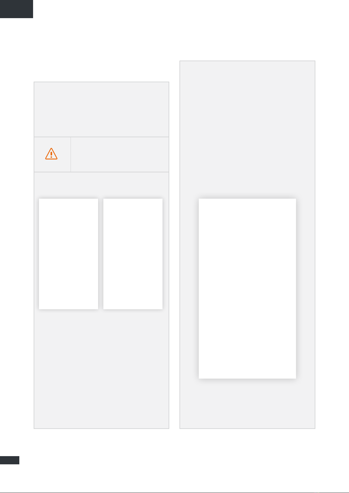
Ensure that you have the following items ready before
installing your terminal:
If any of these items is incorrect, missing or damaged,
please contact STANLine or your retailer.
Please retain the packaging for future use, should you need
to return the product for repair.
Accessories other than those provided may not be
compatible with your terminal.
TO BE PREPARED PROVIDED
•Sealant Teroson MS 930 •1 Box 4G
•Screwdriver PZ1
(if not, any cross-headed) •4 Pads
•Open-end wrench 15/17 mm •2 Covers
•Hex key no3 •1 Cable gland
•Wire stripper •8 x M3 screws; 12 x M4 screws
•Crimping tool •1 x 8 m power cable
•Fuse (<=12A) •2 Faston connectors
5
EN
Description of the terminal
For best performance, the system must be placed
horizontally above the recreational vehicle. Please follow
the installation steps below.
Power supply
terminal block
Sim card
slots
VIEW OF THE INTERFACE WITH COVERS REMOVED
Avoid any contact of thread lock or
Tef-Gel on the radome of the device.
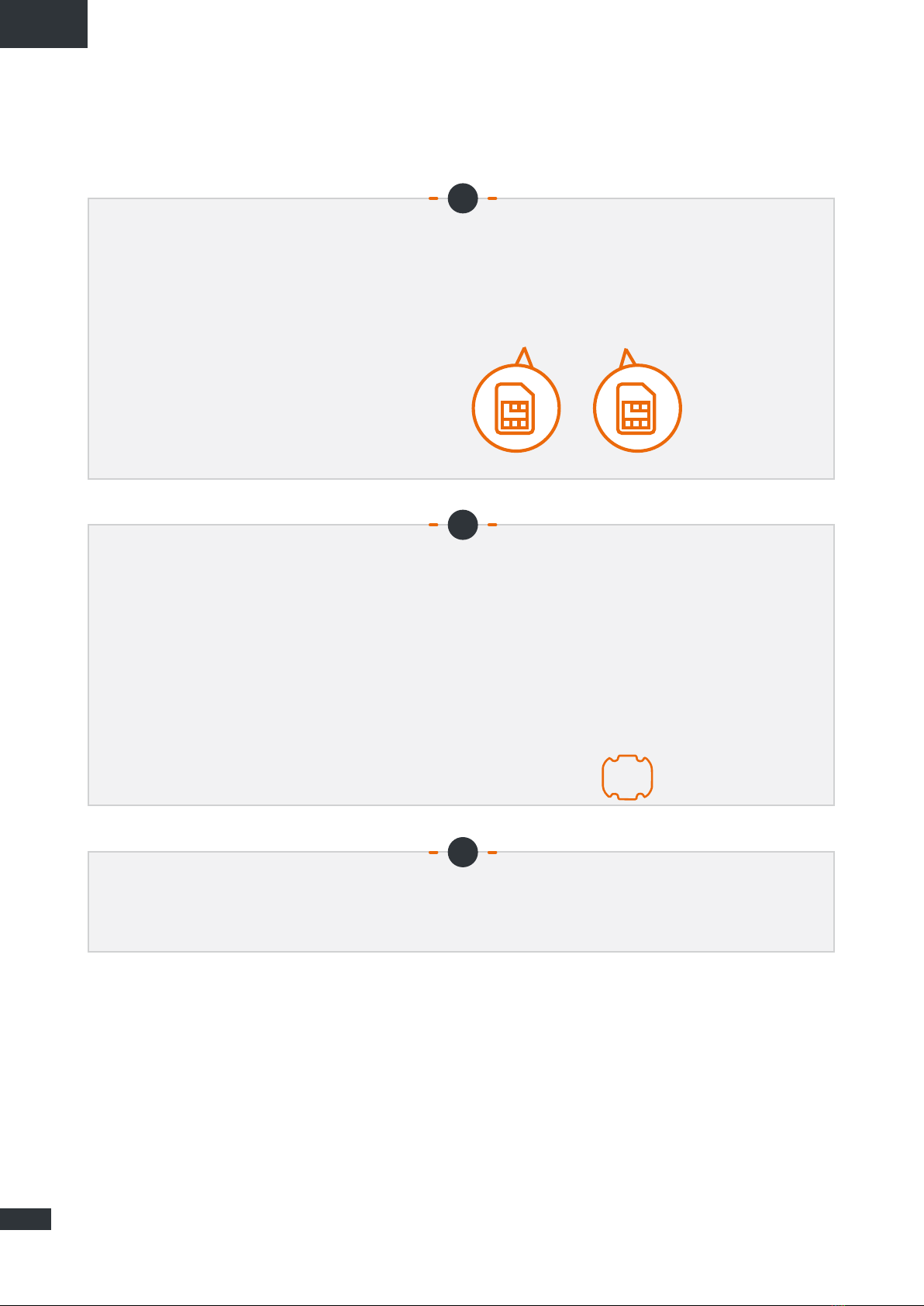
Prerequisites
REQUIRED SIM CONFIGURATION
Depending on how your SIM card(s) are configured, you will need one or more configuration
settings to connect your terminal to the Internet:
•APN setting (Access Point Name).
•PIN code (Personal Identification Number).
Those informations should be provided with your SIM card. Please reach your service provider if not available.
6
EN
Getting started
Your terminal can be installed in 12 steps:
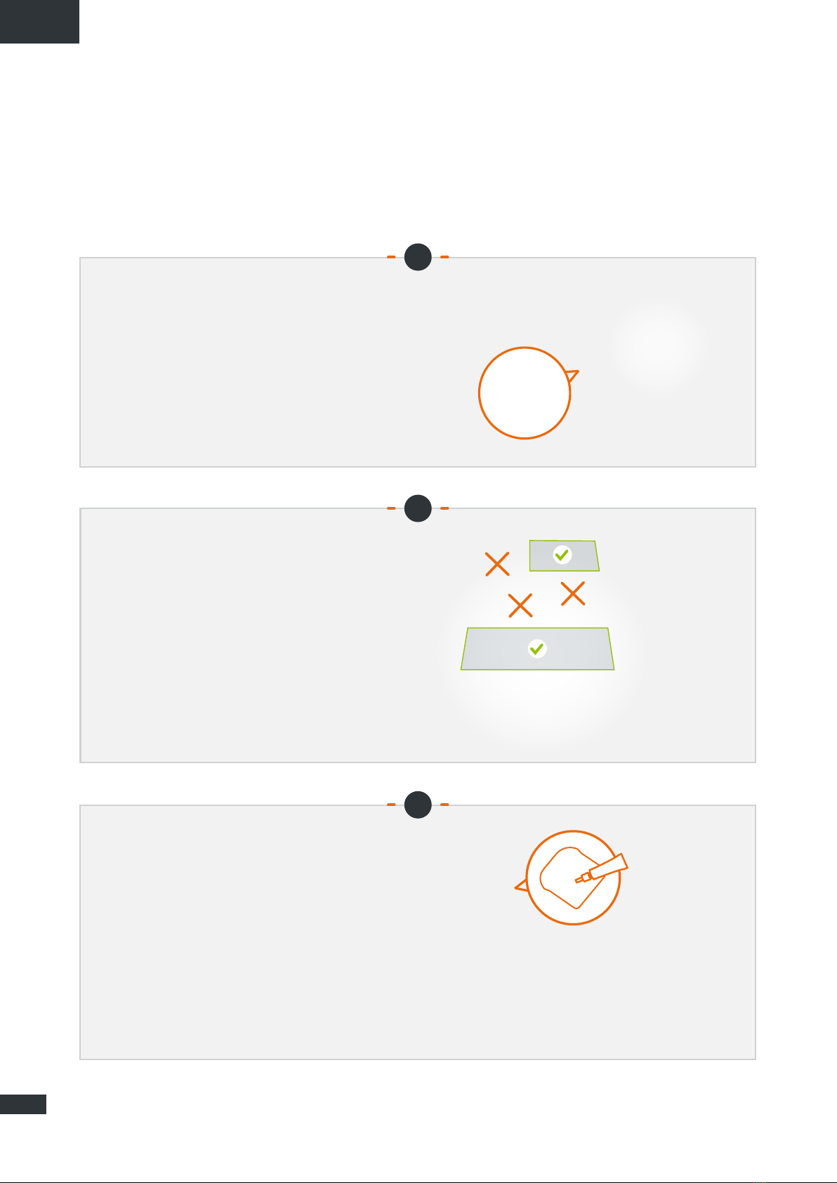
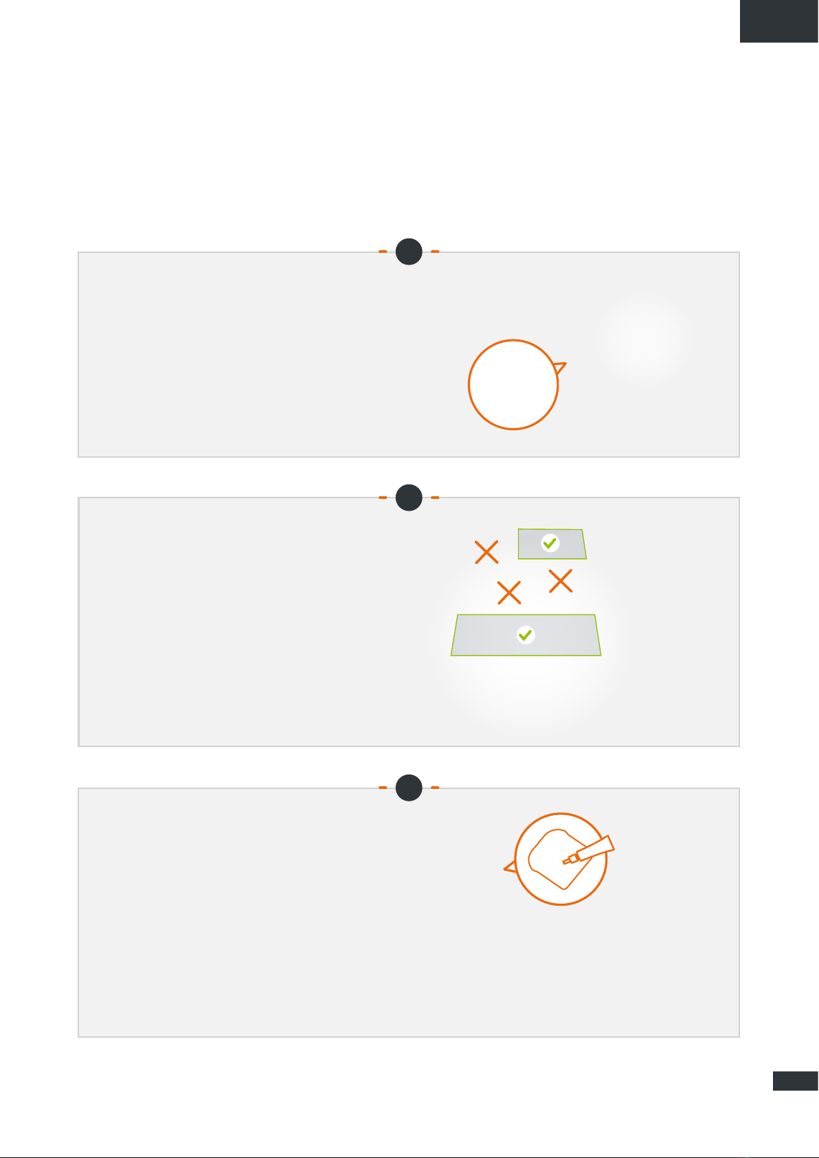
Installing the pads
4 pads are supplied with the Box 4G
to attach it to the roof of your vehicle.
Screw each of the 4 pads to the Box
using the 3 M4 inserts.
STEPS
1
2
3
Applying the sealant
Recommended sealant to stick the Box
on top of the vehicle: Teroson MS 930.
Apply the sealant evenly to the inner side
(ribbed) of the 4 pads.
Choosing the space on the roof
Pick a flat, bare space on the roof of the
RV. Avoid placing the system near the
metal parts.

7
EN
STEPS
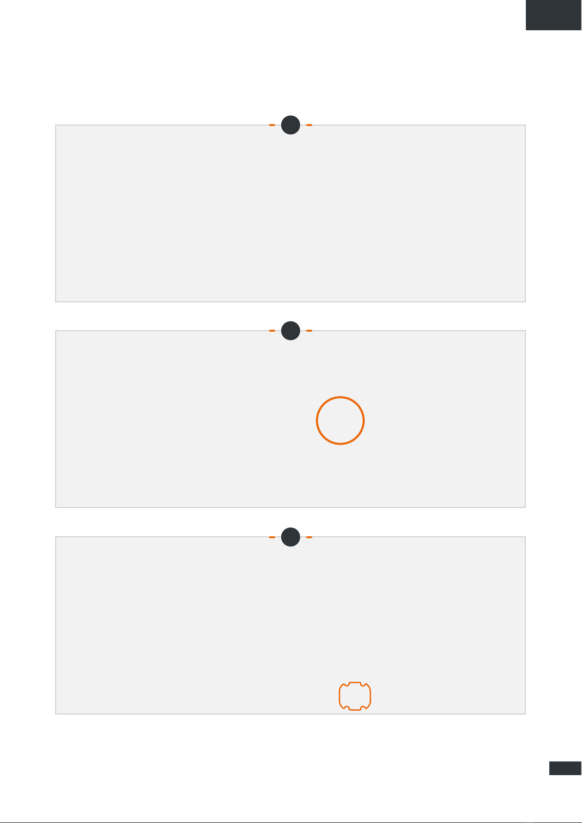
Sticking the Box on top
of the vehicle
Follow the instructions for use of the
assembly product. Stick the Box on
top of the vehicle with the shaped side
towards the front of the vehicle. Keep
the Box in place for 30 min. Wait at least
2 hours before driving.
2H
30 mn
4
5
6
Installing the power cable
Pass the supplied power cable through
the cable gland.
Assembling the cable gland
Attach the cable gland to the perforated
cover with the flat seal and nut supplied.

8
EN
Preparing the power cable
Remove the power cable insulation
(inside the cover, 1 cm +/- 2 mm) to
connect the Faston connectors.
Connecting the Faston connectors
Connect the Faston connectors to
the 2 pins in the left hole (no mounting
direction).
STEPS
7
8
9
Installing the left cover
Screw the cover (4 M3 screws and
washers) by adjusting the length of the
cable (inside the hole). Screw the cable
gland onto the cable.

9
EN
Inserting a SIM card
Insert 1 to 2 SIM cards into the slots in
the right hole.
Installing the right cover
Screw the hatch (4 M3 screws and
washers) fitted with a vent on the right
hole.
Powering the device
Connect the cable to the vehicle power supply (9 to 30 V DC). Requires fuse protection (<=12A).
STEPS
10
11
12
10
EN
Set up
➊App Android/iOS:
Set up the Box with the Android or iOS
"Box 4G STANLine" mobile app available on
Playstore or Apple store. The app can also
be downloaded from the Stanline website
http://stanline.fr/en/box-4g/35-box-4g.html.
The app opens on the home screen,
and the following screen appears:
The screen consists of:
• a top line showing:
- an on/off power button: it enables/ disables
the Box 4G’s LTE/Wi-Fi connections,
- configuration connection status,
- the external connection status
(external LTE or Wi-Fi),
• 5 panels described below to set up the Box.
➋ Configuration Access:
Use the configuration access screen to:
• enter the Box 4G’s configuration access code.
- This code will allow the smartphone/tablet to
pair with your Box 4G to complete the setup.
- This step is essential. If your smartphone/
tablet is not paired with your Box 4G, you will
not be able to set it up.
- This code is available on the back of
the installation notice. It is important that
you keep this code.
Once the code is entered and confirmed, the
connection (key) icon at top changes to green.
Before launching the app, make sure that
Wi-Fi and Bluetooth on your smartphone/tablet
is turned on.

11
EN
➌ 4G/LTE Setup:
Use the 4G/LTE link setup screen to:
• choose the active SIM card (the one shown in
orange),
• enter the active card’s PIN and confirm it,
• select the supplier’s APN:
Most European and North African APNs are
installed. An "Other" field allows you to enter your
APN if it does not appear in the list.
To activate either SIM card, simply click it on the
screen. If the slot is empty, if there is no physical
SIM card, in the Box 4G, it cannot be clicked.
➍ External Wi-Fi Setup:
Use the external Wi-Fi setup screen to:
• select access from among the available Wi-Fi
networks in the "Networks" list,
- showing the reception quality
- showing whether the network is public/private
Information button (forget network, etc.)
available for each network
• enable/disable the Wi-Fi network (green for go/
red for no-go),
If the network is active, the Wi-Fi reception level
appears in the top right; otherwise, the LTE level
is shown,
• enter the password for the selected network
appearing in "My Network" if necessary.

12
EN
➎ Box 4G Wi-Fi Setup:
Use the Box 4G Wi-Fi setup screen to:
• Change the name of the Box’s Wi-Fi network
Click the name to change it,
• change the public/private status of the Box’s
Wi-Fi network.
Click the Wi-Fi logo showing a padlock
- Closed padlock: private network (using the Box
4G in private mode is recommended),
- Open padlock: public network,
• change the password.
- This field appears if the network is private
- The eye button on the right allows you to view
the password
➏ General:
On the "General" screen, you will find:
• a field showing service information such as
firmware version, device serial number, and
modem IMEI number,
• a button to access this user manual in .pdf
format,
• a "RESET" button to restart the device,
• a "FACTORY RESET" button to reset the
device to factory settings. This action will erase
all stored codes passwords as well as the stored
Wi-Fi networks,
• a button to update the Box 4G software. You may
be prompted with software updates.
Note that your connected devices will need
to be reconnected to the network

13
EN
Troubleshooting and FAQ
Appendix
Should you experience any problems with your terminal, please use the table below to find a solution. If you can’t find the
right solution, please contact your retailer.
PROBLEM DESCRIPTION POSSIBLE CAUSE POSSIBLE SOLUTION
Bluetooth icon in Red
Your smartphone/tablet Bluetooth
connection is disabled. Enable your smartphone/tablet Bluetooth connection.
The Bluetooth PIN numbers
you have filled are incorrect.
Please check the code behind your installation notice.
If lost please contact your retailer.
SIM card not present
(not displayed in 4G / LTE
Configuration panel)
Faulty or damaged SIM card. Contact your mobile operator.
SIM card inserted incorrectly. Insert your SIM card correctly following the steps described
under “STEP 10”.
SIM card blocked
(PUK instead of PIN in LTE Panel) You have entered the wrong PIN code. Contact your service provider to obtain a PUK code
to unblock the SIM card.
Internet connection unavailable
or slow
You are not in a 3G/4G service
coverage zone.
Check your network coverage. You should see reception
bars displayed on your terminal’s configuration interface,
together with “3G” or “4G”.
You have used up your Internet
data volume.
Contact your service provider to find out how much data
you have used. If you have exceeded your data allowance,
your bandwidth may be reduced.
The Box 4G is not switched on. Check the power cord. Connect the terminal.
The connection status
is not displayed in Header
You have changed the SIM card settings. Please fill the informations in the 4G / LTE Configuration panel.
You are not in a 3G/4G service
coverage zone. Check your network coverage.
Contacting Technical Support
For any request for assistance, please contact your retailer.
Please have the following information to hand before contacting:
•The serial number (found on the label at the back of your installation notice or accessible via the Android/iOS App in
“General”).
•Firmware version (accessible via the Android/iOS App in “General”).
14
FR
Table des matières
FONCTIONNALITÉS TECHNIQUES 15
PACK 15
CONTENU DU PACK 15
DESCRIPTION DU TERMINAL 16
•Vue de l’interface avec les caches en place 16
•Vue de l’interface sans les caches 16
PRÉREQUIS 16
•Configuration SIM requise 16
DÉMARRAGE 17
• Étape 1 : montage des patins 17
• Étape 2 : choix de l’emplacement sur le toit 17
• Étape 3 : application du mastic 17
• Étape 4 : collage de la Box 18
• Étape 5 : assemblage du presse-étoupe 18
• Étape 6 : montage du câble d’alimentation 18
• Étape 7 : préparation du câble d’alimentation 19
• Étape 8 : connexion des cosses Faston 19
• Étape 9 : montage du cache gauche 19
• Étape 10 : insertion d’une carte SIM 20
• Étape 11 : montage du cache droit 20
• Étape 12 : alimentation de l’appareil 20
CONFIGURATION 21
• Appli Android/iOS 21
• Accès Configuration 21
• Configuration 4G/LTE 22
• Configuration Wi-Fi externe 22
• Configuration Box 4G Wi-Fi 23
• Général 23
DÉPANNAGE ET FAQ 24
ANNEXE 24
CONTACTER LE SUPPORT TECHNIQUE 24

15
FR
Fonctionnalités techniques
ÉMETTEUR-RÉCEPTEUR
Bandes de fréquences
•LTE avec diversité MIMO :
Bande 1 (2100 MHz)
Bande 3 (1800 MHz)
Bande 7 (2600 MHz)
Bande 8 (900 MHz)
Bande 20 (800DD)
Bande 28 (700d)
•UMTS (WCDMA), HSDPA, HSUPA,
HSPA+, DC-HSPA+ avec diversité :
Bande 1 (2100 MHz)
Bande 8 (900 MHz)
Gain d’antenne 2 dBi ± 1dB
Poids du système 2,5 Kg
Dimensions du système L 500 x l 400 x h 170 mm
Type de SIM Mini SIM (Micro et Nano SIM acceptées avec un adaptateur Mini SIM)
CARACTÉRISTIQUES D’ALIMENTATION
Alimentation électrique 9 à 30V DC (connecteurs + câble fournis)
Fonctionnement < 10W
CONDITIONS AMBIANTES
Température de fonctionnement -20°C à +50°C
Température de stockage -40°C à +85°C
INTERFACE
Transmission de données Wi-Fi
Mise en service / Configuration Via Application
INSTALLATION
Fixation Via 4 patins (fournis)
Pack
Contenu du pack
Veillez à préparer les éléments suivants avant
d’installer votre terminal :
Si l’un de ces éléments est incorrect, manquant ou
endommagé, veuillez contacter STANLine ou votre
revendeur. Veuillez conserver l’emballage pour toute
utilisation ultérieure, si vous devez retourner le produit pour
réparation.
Tous accessoires autres que ceux fournis peuvent
ne pas être compatibles avec votre terminal.
À PRÉVOIR FOURNIS
•Mastic Teroson MS 930 •1 Box 4G
•Tournevis PZ1
(à défaut un cruciforme) •4 patins
•Clés plates 15/17 mm •2 caches
•Clé Allen no 3 •1 presse-étoupe
•Pince à dénuder •8 vis M3 ; 12 vis M4
•Pince à sertir •1 câble d’alimentation de 8 m
•Fusible (<=12A) •2 cosses Faston

16
FR
Description du terminal
Pour des performances optimisées, le système doit être
placé horizontalement au-dessus du camping-car. Veuillez
suivre les étapes d’installation ci-dessous.
Bornier
d’alimentation
Logements
pour cartes SIM
VUE DE L’INTERFACE SANS LES CACHES
Évitez tout contact du frein-filet ou Tef-Gel
avec le radôme du dispositif.
Prérequis
CONFIGURATION SIM REQUISE
Selon la configuration de votre ou vos cartes SIM, un ou plusieurs paramètres de configuration seront
nécessaires pour connecter votre terminal à Internet :
•Paramètre APN (Access Point Name, identifiant du point d’accès).
•Code PIN (Personal Identification Number, numéro d’identification personnel).
Ces informations doivent être fournies avec votre carte SIM. Veuillez contacter votre fournisseur de service si vous ne les
avez pas.
17
FR
Démarrage
Votre terminal peut être installé en 12 étapes.
Montage des patins
4 patins sont fournis avec la Box 4G
pour la fixation au toit du véhicule. Visser
chacun des 4 patins à la Box via les 3
inserts M4.
ÉTAPES
1
2
3
Application du mastic
Mastic préconisé pour le collage sur le
véhicule : Teroson MS 930. Appliquer
uniformément le mastic sur la face
interne (nervurée) des 4 patins.
Choix de l’emplacement sur le toit
Définir un emplacement plat et dégagé
sur le toit du camping-car. Eviter la
proximité du système avec les masses
métalliques.

18
FR
ÉTAPES
Collage de la Box
Respecter les consignes d’utilisation
du produit d’assemblage. Coller la Box,
face profilée vers l’avant du véhicule.
Maintenir la Box pendant 30 min.
Attendre 2 heures minimum avant
roulage.
2H
30 mn
4
5
6
Montage du câble d’alimentation
Passer le câble d’alimentation fourni par
le presse-étoupe.
Assemblage du presse-étoupe
Assembler le presse-étoupe avec le joint
plat et l’écrou fournis au cache perforé.
19
FR
Préparation du câble d’alimentation
Dénuder le câble d’alimentation (côté
intérieur du cache sur 1 cm +/- 2 mm)
pour connecter les cosses Faston.
Connexion des cosses Faston
Connecter les cosses Faston aux 2
broches présentes dans la cavité
gauche (pas de sens de montage).
ÉTAPES
7
8
9
Montage du cache gauche
Visser le cache (4 vis M3 et rondelles)
en ajustant la longueur du câble
(intérieur de la cavité).
Visser le presse-étoupe sur le câble.
20
FR
Insertion d’une carte SIM
Insérer 1 à 2 cartes SIM dans les
emplacements situés dans la cavité
droite.
Montage du cache droite
Visser la trappe (4 vis M3 et rondelles)
munie d’un évent sur la cavité droite.
Alimentation de l’appareil
Connecter le câble à l’alimentation du véhicule (9 à 30V DC). Nécessite une protection par un fusible (<=12A).
STEPS
10
11
12
Table of contents
Languages:


