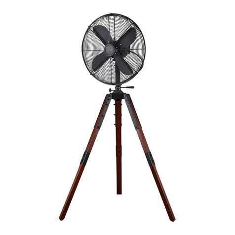
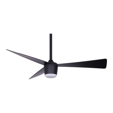
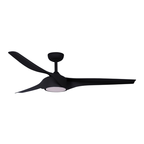
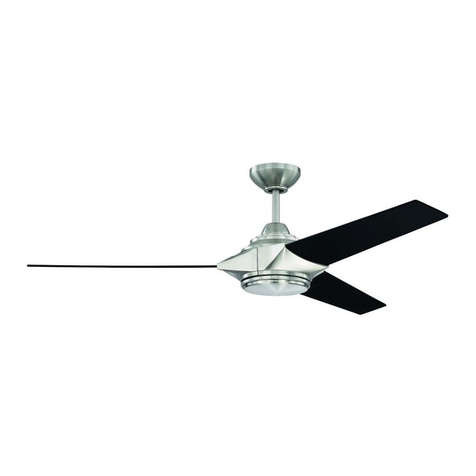
Star Fans Start propeller User manual

User ’s manual
WARNING : Read and follow these instructions carefully and be mindful of all warnings shown throughout.
STAR PROPELLER
KGS.
LBS.
Net weight
STAR PROPELLER
User's manual
User ’s manual
WARNING : Read and follow these instructions carefully and be mindful of all warnings shown throughout.
STAR PROPELLER
KGS.
LBS.
Net weight

WARNING : TO REDUCE THE RISK OF FIRE, ELECTRICAL SHOCK, OR INJURYS,
PLEASE OBSERVE THE FOLLOWING :
READ AND SAVE THESE INSTRUCTIONS
P1
1]. To ensure the success of the installation, be sure to read the instructions and review the diagrams
thoroughly before beginning.
2]. To avoid possible electric shock, be sure electricity is turned off at the main power box before wiring.
All electrical connections must be made in accordance with local codes, ordinances and/or the
National Electric Code. If you are unfamiliar with the methods of installing electrical wiring and
products, secure the services of a qualified and licensed electrician as well as someone who can
check the strength of the supportive ceiling members and make the proper installations and
connections.
3]. Make sure that your installation site will not allow rotating fan blades to come in contact with any
object. Blades should be at least 7 feet from the floor when the fan is in operation.
4]. If possible, mount ceiling fan on a ceiling joist - the joist must be able to support the motion and weight
of the moving fan. If the fan will be mounted on a ceiling outlet box, make sure it will support at least
50 lbs. The box and its supporting members must not be able to twist or work loose.
DO NOT USE PLASTIC BOXES. Installation on a concrete ceiling should be performed by qualified
personnel.
5]. Fan motor housing should be kept in carton until ready to be installed to protect its finish. If you are
installing more than one ceiling fan, make sure that you do not mix fan blade sets.
6]. After making electrical connections, spliced conductors should be turned upward and pushed
carefully up into outlet box. The wires should be spread apart with the grounded conductor and the
equipment - grounding conductor on one side of the outlet box and the " HOT " wires on the other side.
7]. Electrical diagrams with various different colors are for reference only. Make sure that the fan voltage
(120) is compatible with your own electrical system.
8]. After fan is completely installed, check to make sure that all connections are secure to prevent fan
from falling and/or causing damage or injury.
9]. The fan must be turned off and stopped before reversing fan direction.
10]. This fan is suitable for damp location.
"WARNING": "To Reduce The Risk Of Fire, Electric Shock, Or Personal Injury, Mount
To Outlet Box Marked Acceptable for Fan Support of 15.9 kg (35 lbs) or less And Use
Mounting Screws Provided With The Outlet Box."
www.starfans.co

Unpack and inspect fan carefully to be certain
all contents are included.
Flat Washer x3
Spring Washer x3
Machine Screw x2
Wood Screw x3
For Mounting Bracket:
For Wire Connection:
Wire Nut x 3
For Blade Installation:
Plastic Bushing x 7 (one spare bushing included)
Blade Screw x 7 (one spare screw included)
L type small screw driver (hexagon)
Hardware Bag
For Blade Balance :
Balanced slide x 1
Weight block (3G x 5)
3 GM
3 GM
3 GM
3 GM
3 GM
Yoke cover
Assembly
Mounting Bracket
Canopy
Downrod
Fan assembly
Blade(3)
Deco Ring
Wall Control
Hardware Bag
Wood Screw x 2
Screw x 2
Wire Nut x 2
P2
Unit pack / all in one box
(For Wood beam)
www.starfans.co

WARNING: blades should be at least 7 feet from floor
OFFOFFOFF
Turn off power at breaker box to avoid possible
electrical shock.
Use metal outlet box suitable for fan support.
Outlet box must support 35 lbs min.
Note 1: Note 2:
1. HANGING SYSTEM INSTALLATION
1A.Installing mounting bracket to ceiling outlet box
2Screw (2)
(Loosening)
1Outlet Box
Mounting
Bracket
1Install mounting bracket to outlet box in ceiling by
using screws included with the outlet box and washers
from the hardware bag.
2 Loosen the bottom screws from Mounting Bracket.
Do not remove.
Yoke
Downrod
Assembly
Fan
Assembly
Deco Ring
Wire Connectors
from Yoke Cover
Assembly
Cross Pin
Cotter Pin
Jam Screw
with Hex Nut(1)
(Tightening)
Wire Connectors
from Fan
Jam Screw
with Hex Nut(1)
(Loosening)
Canopy
Yoke Cover
Assembly
Cross Pin
Cotter Pin
Canopy
Yoke cover
Downrod
Deco Ring
Canopy
Yoke Cover
Assembly
Wires
1B. Installing Downrod and Yoke
1
2Insert downrod through Canopy, Deco Ring and Yoke Cover and feed motor lead wires through Downrod.
3
4
5
6
7
Fig.1 Fig.2 Fig.3
See Fig.1
Remove cross pin and cotter pin from downrod.
Loosen 1 Downrod jam screws at Yoke. Insert Downrod Assembly into Yoke.
Insert the cross pin through Yoke & Downrodand secure with cotter pin.
Tighten Downrod jam screws to furthersecure Downrod.
Attach Wire Connectors from Yoke Cover Assembly and from fan to tight.
Pull down the Yoke Cover Assembly.
See Fig.2
See Fig.3
P3
Mounting
Bracket
Lift fan assembly onto Mounting Bracket. Rotate fan to let the groove on the ball engages the
ridge in the Mounting Bracket.
1C. Hanging the fan
Ridge Ball Groove
Mounting
Bracket
P4
2. WIRE CONNECTION
2A. Attaching safety cable to ceiling joist
Safety Cable
Safety
cable Flat Washer
Spring Washer
Wood Screw
Outlet Box
Use wood screw, spring washer, and flat
washer from hardware bag. Pass wood
screw through closed loop of safety
cable. Secure wood screw to ceiling joist
through any available slot on mounting
bracket. Make sure safety cable has
beentightened securely.
CAUTION: THE WOOD SCREW AND
ITS SUPPORT MUST BE ABLE TO
FULLY SUPPORT THE WEIGHT OF AT
LEAST 100 LBS.
Canopy
Mounting Bracket
2B.Make wire connection - for Wall Controller
White
Green
( Motor - N )
( Motor - L )
Black
( from downrod )
Green
( AC - L )
( AC - N )
From Fan From House
1Connect two green wires from fan and green wire from house by wire nut.
2Connect white wire from fan and white wire from house by wire nut.
3Connect black wire from fan and black wire from outlet box.
4Connect black wire from outlet box and black wire from wall control
marked ”To FAN” by wire nut.
5Connect black wire from wall control marked ”To HOT” and black wire
from House by wire nut.
6Connect green/yellow wire from wall control and green wire from
House by wire nut.
White
Black
TO HOT
TO FAN
Wall Controller
Outlet Box
1
2
3 4 5
( from mounting bracket )
Green
Green / Yellow
6
www.starfans.co

Mounting
Bracket
Lift fan assembly onto Mounting Bracket. Rotate fan to let the groove on the ball engages the
ridge in the Mounting Bracket.
1C. Hanging the fan
Ridge Ball Groove
Mounting
Bracket
P4
2. WIRE CONNECTION
2A. Attaching safety cable to ceiling joist
Safety Cable
Safety
cable Flat Washer
Spring Washer
Wood Screw
Outlet Box
Use wood screw, spring washer, and flat
washer from hardware bag. Pass wood
screw through closed loop of safety
cable. Secure wood screw to ceiling joist
through any available slot on mounting
bracket. Make sure safety cable has
beentightened securely.
CAUTION: THE WOOD SCREW AND
ITS SUPPORT MUST BE ABLE TO
FULLY SUPPORT THE WEIGHT OF AT
LEAST 100 LBS.
Canopy
Mounting Bracket
2B.Make wire connection - for Wall Controller
White
Green
( Motor - N )
( Motor - L )
Black
( from downrod )
Green
( AC - L )
( AC - N )
From Fan From House
1Connect two green wires from fan and green wire from house by wire nut.
2Connect white wire from fan and white wire from house by wire nut.
3Connect black wire from fan and black wire from outlet box.
4Connect black wire from outlet box and black wire from wall control
marked ”To FAN” by wire nut.
5Connect black wire from wall control marked ”To HOT” and black wire
from House by wire nut.
6Connect green/yellow wire from wall control and green wire from
House by wire nut.
White
Black
TO HOT
TO FAN
Wall Controller
Outlet Box
1
2
3 4 5
( from mounting bracket )
Green
Green / Yellow
6
www.starfans.co

SCREW
SPEED
CONTROL
OUTLET BOX
AFTER ALL WIRES ARE CONNECTED:
( 1 ) Attach wall control unit to outlet box using the
two 6-32 screws provided.
( 2 )Attach wall plate to the switch control front.
! WARNING
To avoid possible fire or shock, make sure that the electrical wires are completely inside
the outlet box and not pinched between the wall plate and the wall.
! WARNING
Check to see that all connections are tight, including ground, and that no bare wire is visible
at the wire connectors, except for the ground wire. Do not operate fan until the blades are
in place. Noise and fan damage could result.
Align Holes
Deco Ring
3. CANOPY INSTALLATION
Push up canopy until two pre-screwed screws on Mounting Bracket are engaged with two key holes on Canopy.
Rotate Canopy slightly until two pre-screwed screws heads are engaged in the narrow end of key holes.
Tighten both screws.
Push Deco Ring up to Canopy, align holes on Canopy withribs on Deco Ring, and push “snap-in”.
Note: Two screws are pre-screwed on Mounting Bracket for Canopy installation.
1
2
3
4
Key Hole (2)
Canopy
Screw (2)
1
2
3
4
Canopy
P5
www.starfans.co

4. BLADE INSTALLATION
Attach blades to motor by using Plastic Bushing & Blade screws provided in the hardware bag.
(* Repeat this step for every blade until the 3 blades are installed firmly. Do not tighten the screws too
hard to prevent harming the wood.)
Blade Screw
Plastic Bushing
L Type Small Screw Driver
(Hexagon)
5.Turn on power at breaker box,Your fan is ready for operation.
OFF
OFF
OFF
ON
P6
Blade(3)
www.starfans.co

www.starfans.co

Troubleshooting
Prior to submitting a claim for a defective or failed fan, or prior to removal of your fan from its installation location, please
read the below possible symptoms and solutions or contact the Star Fans company via email for trouble shooting
assistance.
Failure: Fan will not start
Failure: The fan is noisy
Failure: Fan Wobble
Solution: check power, circuit fuses or breakers.
Caution! Make sure the power is turned offbefore performing the following steps:
Remove canopy and check wire connections, check wall control transmitter connections,
double check the winter/summer switch on the motor.
Solution: Check the screws that attach the fan blade to the motor hub, Make sure outlet
box is secured to building structure, if necessary use the wood screws provided to further
secure outlet box to joist, Make sure hanger bracket is secure to the outlet box.
Solution: Make sure outlet box is secured to building structure, if necessary use the wood
screws provided to further secure outlet box to joist, Make sure hanger bracket is secure to
the outlet box.
*If the above doesn’t solve the wobbling Use the balancing kit provided (instructions includ-
ed with balancing kit).
LIMITED LIFETIME WARRANTY
The Star Fans warranty is for one year from the date of purchase from an authorized Star Fans dealer, except for
the motor which is granted a five year warranty (excluding wall controls and electrical components e.g switches
and capacitors), to the original purchaser or user.
Star Fans warrants this fan to be free from defects in material and workmanship for one year from the date of
purchase with exception of the motor. The company’s only obligation under this limited warranty is to replace,
repair or refund the purchase of a fan confirmed by Star Fans to be defective in material or workmanship after
the motor only is returned to Star Fans by the original purchaser along with a proof of purchase and with shipping
charges prepaid.
This warranty will not apply to fans which have been damaged as a result of improper installation, removed from
the original installation or subjected to use for which the fan was not designed. The customer is responsible for
any cost of removing the old fan, installing a new fan or any other costs. Star Fans shall under no circumstances
be liable for any incidental or consequential damages.
Warranty Service Information
To obtain warranty service during the warranty period, the purchaser should return the fan with the sales receipt
to the Star Fans company. The address can be found on starfansusa.com. The company will either repair or
replace the fan after verifying the legitimacy of the warranty claim. This is a limited warranty. For any more
information please email: info@starfans.co
There is no warranty for fans used with any non Star Fans devices (wall control, electrical dimmer switches, etc’…);
purchased or installed outside the United States; fans owned by someone other than the original purchaser; fans
for which proof of purchase has not been established; fans purchased from an unauthorized dealer; ordinary
wear and tear; minor cosmetic blemishes; refurbished fans; and fans that are damaged due to any of the follow-
ing: improper installation, misuse, abuse, improper care, failure to
follow Star Fans instructions, accidental damage caused by the fan owner or related parties, modifications to the
fan, improper or incorrectly performed maintenance or repair, improper voltage supply or power surge, use of
improper parts or accessories, failure to provide maintenance to the fan, or acts of God (e.g. flood).
STAR FANS

STAR FANS
www.starfans.co
Star Propeller
Thank you for buying a
Star Propeller fan!
Your new purchase is a
beautiful and energy saving
addition to your space.
Table of contents
Other Star Fans Fan manuals
Popular Fan manuals by other brands

NuAire
NuAire Neonaire NE20BT Installation and Maintenance
Accurex
Accurex XRSI Installation, operation and maintenance manual
Monte Carlo Fan Company
Monte Carlo Fan Company 5WF52XXD-L Series Fan Owner's guide and installation manual
Broan
Broan QTXE110S instructions

Fujitsu
Fujitsu UTZ-BX025A Maintenance manual
Mistral
Mistral MCHARGE14 instruction manual

