Star Fans STAR X User manual

STAR X
User's manual
WARNING :
Read and follow these instructions carefully and be mindful of all warnings shown throughout.

WARNING : TO REDUCE THE RISK OF FIRE, ELECTRICAL SHOCK, OR INJURYS,
PLEASE OBSERVE THE FOLLOWING :
READ AND SAVE THESE INSTRUCTIONS
P1
1]. To ensure the success of the installation, be sure to read the instructionsand review the diagrams
thoroughly before beginning.
2]. To avoid possible electric shock, be sure electricity is turned off at the mainpower box before wiring.
All electrical connections must be made in accordance with local codes, ordinances and/or the
National Electric Code. If youare unfamiliarwith the methods of installing electrical wiring and
products, secure the services of a qualified and licensed electricianas well as someone who can
check the strength of the supportive ceiling members and make the proper installations and
connections.
3]. Make sure that your installation site will not allow rotating fan bladesto come in contact with any
object. Blades should be at least 7 feet from the floor when the fan is in operation.
4]. If possible, mount ceiling fan on a ceiling joist - the joist must be able to support the motion and weight
of the moving fan. If the fan will be mounted on a ceiling outlet box, make sure it will support at least
50 lbs. The box and its supporting members must not be able to twist or work loose.
DO NOT USE PLASTIC BOXES. Installation on a concrete ceiling should be performed by qualified
personnel.
5]. Fan motor housing should be kept in carton until ready to be installed to protect its finish. If you are
installing more thanone ceiling fan, make sure that you do not mix fan blade sets.
6]. After making electrical connections, spliced conductors should be turned upward and pushed
carefully up into outlet box. The wires should bespread apart with the grounded conductorand the
equipment - grounding conductoron one side of the outlet box and the " HOT " wires on the other side.
7].Electrical diagramswith various different colors are for reference only. Make sure that the fanvoltage
(120) is compatible with your own electrical system.
8]. After fanis completely installed, check to make sure that all connections are secure to prevent fan
from falling and/or causing damage or injury.
"WARNING": "To Reduce The Risk Of Fire, Electric Shock, Or Personal Injury, Mount
To Outlet Box Marked Acceptable for Fan Support of 15.9 kg (35 lbs) or less And Use
Mounting Screws Provided With The Outlet Box."
www.starfans.co
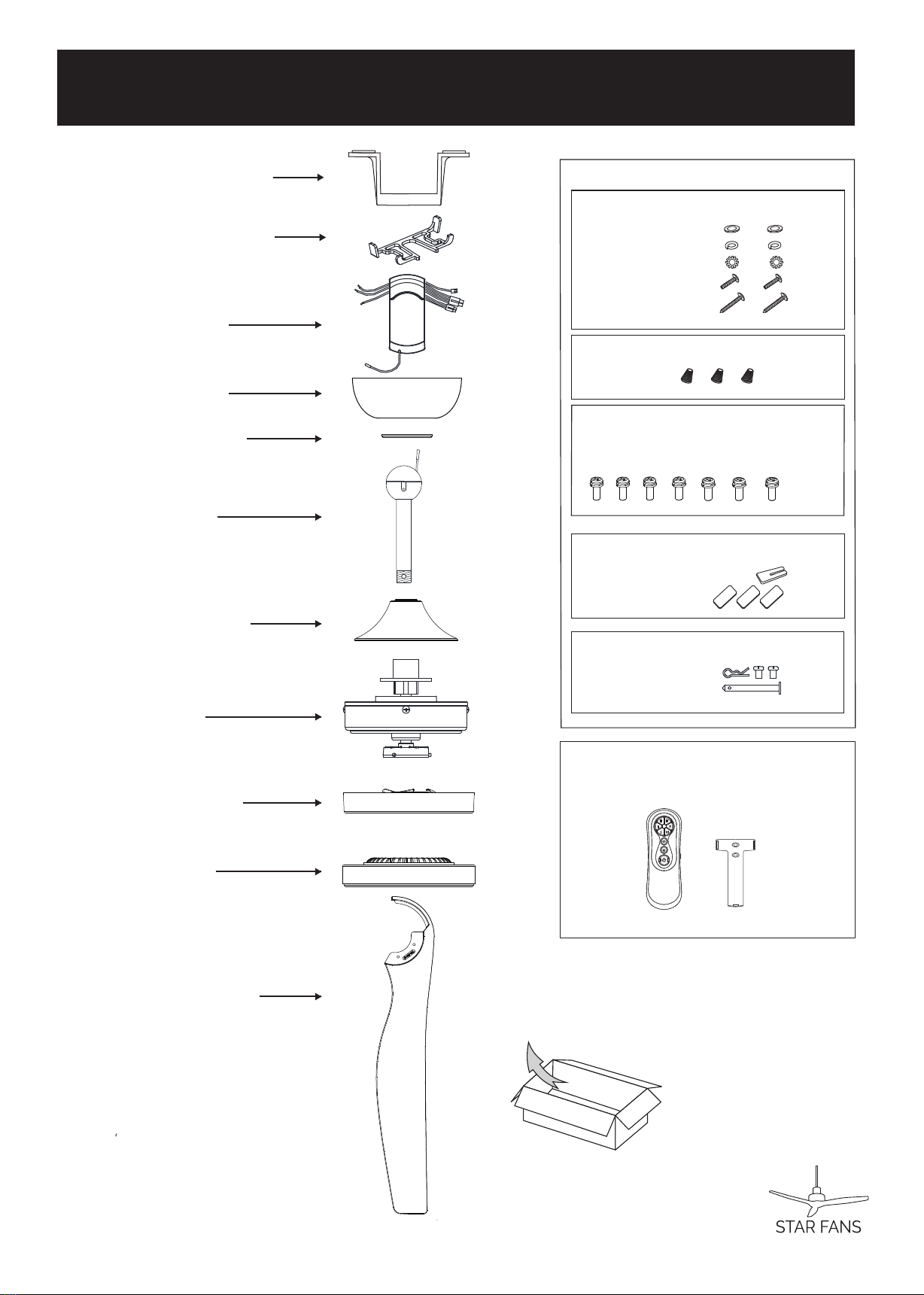
Unpack and inspect fan carefully to be certain
all contents are included.
Flat Washer x2
S
Locker Washer
pring Washer x2
x2
Machine Screw x2
Wood Screw x2
Fo r Mo u n ti n g B r ac k et :
For Wire Connect ion :
Wire Nut x 3
Fo r B l ad e In st al lat io n :
Blade Screw x 7 (one spare screw included)
Har d ware Bag
F
For Downrod Installation:
or Blad e B al anc e :
B
Set screws x 2
Hitch pin x 1
Lock pin x 1
alanc ed slide x 1
Weight block (3G x 3)
3 GM
3 GM
3 GM
Receiver
Mount ing Bracket
Downrod
Canopy
Canopy cover
Remote Cont rol
P2
xobenonilla/kcaptinU
(For Wood beam)
Bottom cover
Light kit
Motor
Coupling cover
Blades
Downrod Stopper
www.starfans.co

OFFOFFOFF
Tur n off po we r at breaker box to avoid possible
electrical shock.
Use metal outlet box suit able for fan su pport.
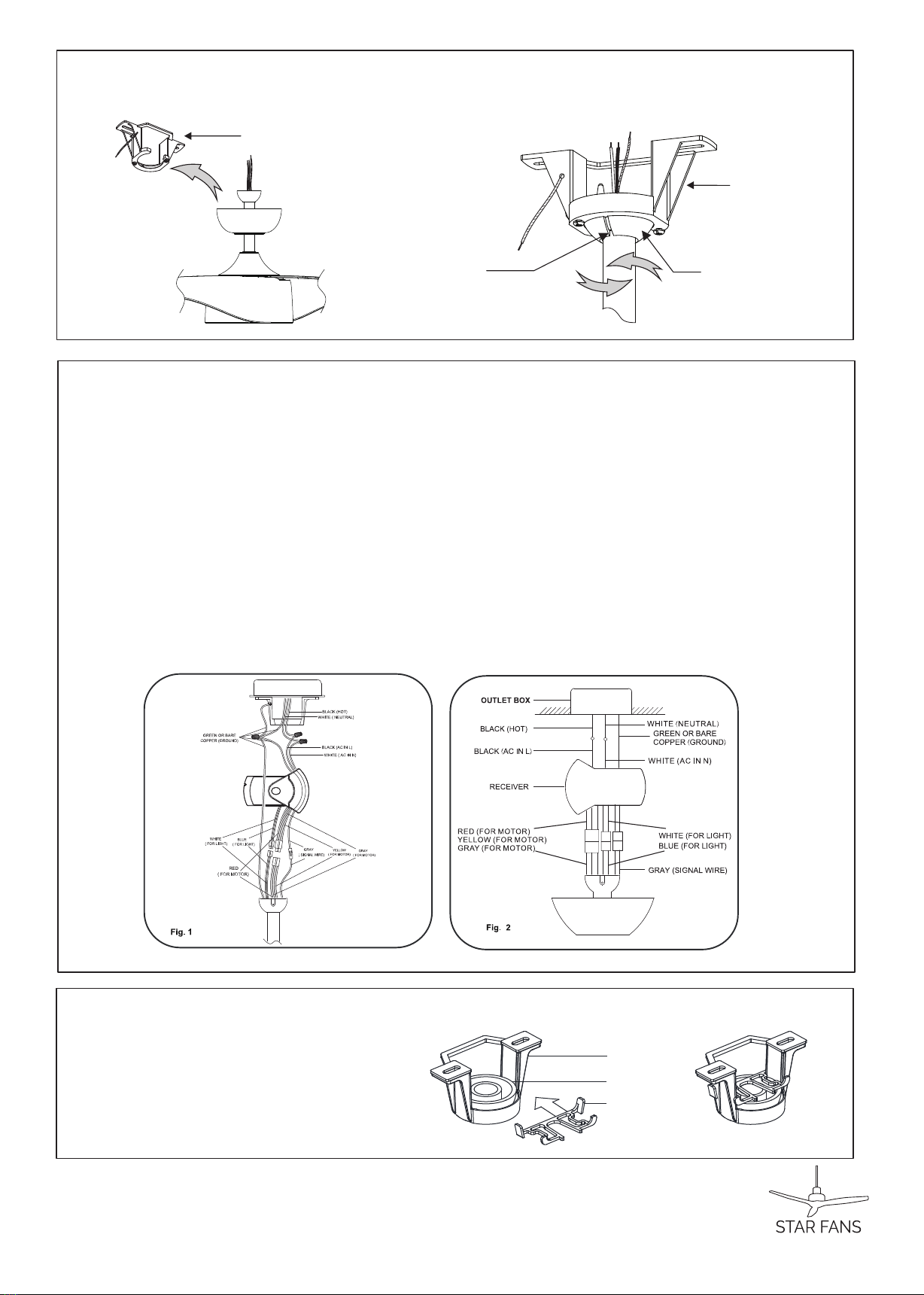
1A.Installing mounting bracket to ceiling outlet box
2
(Loosening)
1Outlet Box
Mounting
Bracket
1Install mounting bracke t to outlet box in ceiling by
using screws included with the outlet box and washers
from the hardwa re bag.
2Loosen the bottom screws from Mounting Bracket.
www.starfans.co

P4
www.starfans.co
3. FAN INSTALLATION
2. BLADE INSTALLATI ON
Blade(3)
Blade screw
Attach blades to motor by using & Blade screws provided
in the hardware bag.
(* Repeat this step for every blade until the 3 blades are
installed firmly. Do not tighten the screws too hard to
prevent harming the plastic.)
Downrod
Downrod
Rubber Cover
Hanger ball
Canopy
Canopy cover
Coupling cover
Set screws
Hitch pin
Lock pin
Mounting
Bracket
L
Step 1. Receiver to House Supply Wires Electrical Connections:
Connect the WHITE wire (Neutral) from the outlet box to the WHITE wire marked ‘AC in N’ from the receiver.
Connect the BLACK wire (Hot) from the outlet box to the
BLACK wire marked ‘AC in L’ from the receiver. Secure all wire connections with the plastic wire nuts
provided.(Fig.1)
Step 2. If you r outlet box has a GROUND wire (Green or Bare Coppe r) connect t his wire to the Hanger Ball and
Hanger Bracket Ground wi res. If yo ur outlet box does not have a Ground Wire, then connect the Hanger Ball and
Hanger Bracket Ground Wi res toget her. Secure wire connectio n wit h plastic wi re connector provided.(Fig.1)
Step 3. Motor to receiver wi res elect rical connections:Connect the 4P-4P for moto r/2P-2P for light/G ray-gray
for signal from moto r to recei ver.(Fig. 2)
After all splices are made, check to make sure there are no loo se strands. As an additio nal precaution we
suggest to secure the plastic wire connecto rs to the wire s wit h elect rical tape .
ift fan assembly onto Mounting Bracket. Rotate fan to let the groove on the ball engages the
ridge in the Mounting Bracket.
3A. Hanging the fan
3B
3C. Installation Downrod stopper
.Connect the wire
Ridge Ball Groove
Mounting
Downrod
stopper
Hanger ball
Bracket
Mounting
Bracket
P5 www.starfans.co
Installation downrod stopper
on the hanger ball.
Align Holes
Deco Ri ng
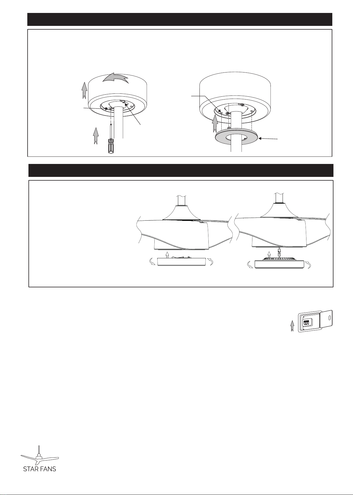
4. CANOPY INSTALLATION
Push up canopy until two pre -screwed screws on Mounting Bracket are engaged with two key holes on Canopy.
Rotate Canopy slightly until two pre -screwed screws heads are engaged in the narrow end of key hol es.
Tighten both screws.
Push Deco Ring up to Canopy, align holes on Canopy w ith ribs on Deco Ring, and push “snap-in”.
Note: Two screws are pre-screwed on Mo unting Bracket f or Canopy installation.
1
2
3
4
Key Hole (2)
Canopy
Screw (2)
1
2
3
4
Canopy
P6
www.starfans.co
5. Turn on power at breaker box, Your fan is ready for operation.
Inst all the ligh t kit
1.Firmly snap the wire
connec t ion plu g s toget her.(Fig.3)
2.Attach t he lig ht kit assem b ly to
the ligh t kit housing by turning
clockwi se unt il snug.(Fig.3)
Inst all the cap for non-light use
1.Raise t he cap and secure i t t o
the f an b y t ur ning t he co ver
cloc kwi se until snu g.
DO NOT OVERTIGHTEN(Fig.4)
OFF
OFF
OFF
ON
5. LIGHT AND BOTTOM COVER
Fig.4Fig.3

1. TURN ON THE FAN
1
2. REVERSE FUNCTION BUTTON
Press any speed control button to turn on the fan and control the ceiling
fan speed from low to high. Button (I) is for the lowest speed, and button (VI)
is for the fastest speed.
Press this button to activate the reverse running function. The fan should run
in the forward direction for SUMMER setting and in reverse for WINTER setting.
3. LIGHT CONTROL BUTTON: (if the light kit installed)
Press to turn the light on and again to turn the light off.
By desault the light will come on whenpower to the fan is turned on.
4. TURN OFF THE FAN
Press this centre button to turn the fan off.
6.Remote Control Operation
2
3
4
Note: The auto learning function will only occur within 60 seconds of turning the fan’s
AC power ON.
1.Select desired frequency from the back of transmitter.
2.Press the transmitte r’s “off” button and hold the “o ff” button for over 10 seconds. Once the
receiver has detected the frequenc y, the down light of your fan if applicable will blink twice.
(There is no indication if your fan is not equipped with a light).
Note: The learning frequency function will continue to retain the last set frequency even when
the AC power is shut off.
The DC motor has a built in safety feature against obstruction during operation, if the fan motor
senses a obstruction for 60 seconds or more it will get locked and will not rotate until the
obstruction has been removed and the power has been disconnected for 5 seconds.
3.Over 60W protection: When the receiver detects motor power consumption which is greater
than 60W, the receive r’s power will stop and operation will be immediately discontinued, if you
want to re-start the fan, please remove obstacles and disconnect the power by turning off the
circuit breaker. And turn the power on after 5 seconds.
4.” DIM” and “ON/OFF” dip switch: The “DIM” selection is the light dimmable selection and
is to be used with all bulbs except for CFL bulbs.The” ON/OFF” selection is for CFL bulbs.
DIP Switches
DIP Switche configuration examples
Transmitter1 Transmitter2 Transmitter 3
DIP Switches
set to 00000
Battery
Battery cover
DIP Switches
set to 10000
DIP Switches
set to 11000
P6
ON
ON ON ON

Table of contents
Other Star Fans Fan manuals


Popular Fan manuals by other brands

Fanimation
Fanimation Edgewood TF100 Series Specification sheet

Sulion
Sulion BORNEO 075751 Assembly instructions

Luminance Brands
Luminance Brands kathy ireland HOME MIDWAY ECO LED CF955LBS00 owner's manual

Hello Kitty
Hello Kitty KT3070 user manual

Panasonic
Panasonic WhisperGreen FV-08VKS2 Specifications

Trane
Trane ILLUSION MCD Series installation manual


