Star Headlight & Lantern Lineum Star Phantom ULB48-TD User manual
PLIT505 REV. B 9/13/17
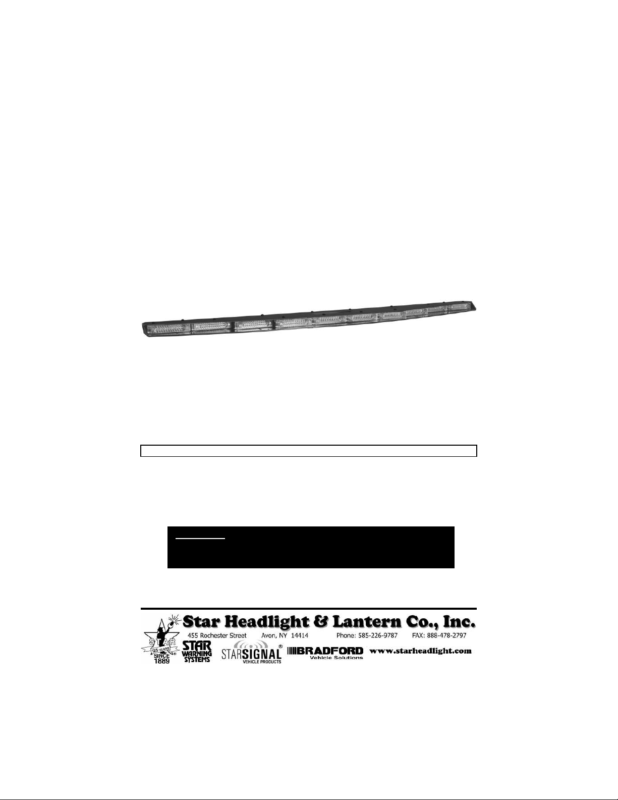
Lineum Star Phantom
Lineum Star Phantom
®
IMPORTANT: Please read all of the following instructions before installing your new warning light.
Dual Color Un ercover Interior LED Lightbar
Please Note: These instructions are provi e as a general gui eline only.
Specific mounting an /or wiring, may be necessary an are the sole
responsibility of the installer. Star Hea light & Lantern Co., Inc. assumes no
responsibility for the integrity of the installation for this or any of its pro ucts.
Mo el ULB48-TD

-1-
The following mounting instructions describe the standard, most common way to
mount this light. This method may or may not apply to your vehicle. Because
vehicles can vary widely in their design, it may be necessary to configure the brackets
differently than described. Some applications may require you to design your own
custom brackets. The installer assumes all responsibility for the integrity of the
installation. It is the sole responsibility of the owner to ensure the light is secure.
Mounting
Please review the Programming section BE ORE mounting your light.
There are several options you may wish to set prior to installation.
P30094-10
(QTY=2
#10-32 SERRATED LANGE NUT
P30150-97-2P
(QTY=2
SLOTTED STRIAGHT BRACKET
P30093-5
(QTY=2
#8 NUT
P30073-3
(QTY=2
#8 TOOTH WASHER
P30150-97P
(QTY=2
DOUBLE SLOTTED "L" BRACKET
P30073-4
#8 LAT WASHERS
P30053-29
(QTY=2
#8-32 x
38
" PHILIPS HEAD SCREW
P30053-24
#8 x
38
" SEL -TAPPING PHILIPS HEAD SCREW
P30053-24
(QTY=6
#8 x
38
" SEL -TAPPING PHILIPS HEAD SCREWS
P30073-4
#8 LAT WASHER
P30150-79P
(QTY=2
ORKED "L" BRACKET (Style 1)
P30150-189P
(QTY=2
ORKED "L" BRACKET (Style 2)
P30076-8
(QTY=2
1/4" LAT WASHER
(USE AS SPACER)
P30054-27
(QTY=2
#10-32 x 1/2" CARRIAGE BOLT
P30073-4
(QTY=12
#8 LAT WASHERS
P30150-220P
(QTY=2
ATTACHING BRACKET
The
Star Phantom
®
line of lights is designed to be
mounted on the inside of your vehicle. They are not intended for
exterior applications and are not warranted against water damage.
It is the sole responsibility of the owner to ensure the warning light is
secure. Check your light every time you enter the vehicle to ensure that
it is mounte securely. The manufacturer assumes no responsibility for
the secure mounting of this light.
-2-
P30073-4
#8 LAT WASHER
Mounting (CONT'D
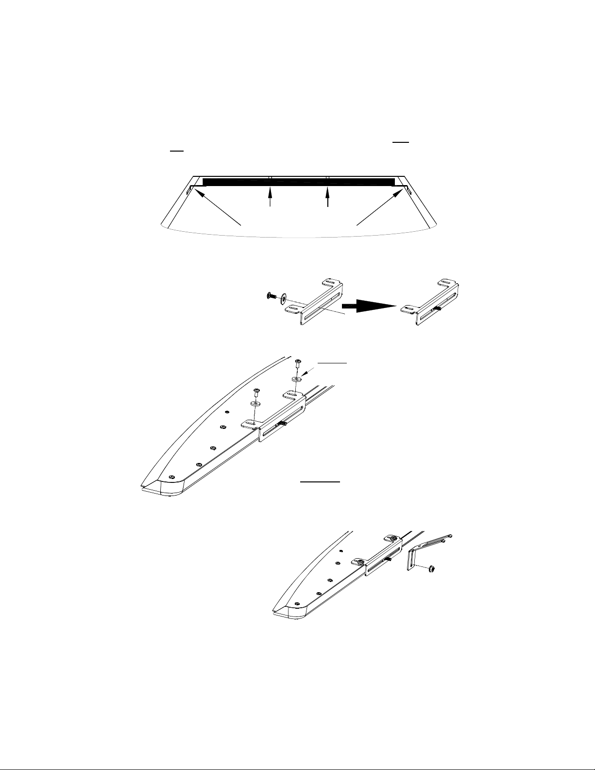
1. Insert a carriage bolt through
one of the 1/4” washers and
slide it through the back of each
of the brackets. Please note
that washer is use as a spacer
on the square neck of the
carriage bolt.
2. Remove two of the #8 x 1/2" self-tapping
Phillips pan head screws on one side of the
light. Using the #8 washers enclosed and
assemble as shown to the left.
CAUTION: Take extreme caution not to
over tighten the screws!!!
3. Place one of the forked “L”
brackets on the bolt and secure it
with one of the nuts. Note:
There are two ifferent style
forke brackets inclu e . Use
the one that suits your
application best. Leave the nut
slightly loose to allow for minor
adjustments during the
remainder of the installation.
Corner Post Brackets
Forke Brackets
This light is designed to be mounted in the rear window of a vehicle using both the forked
brackets an the corner post brackets. Failure to use both brackets could result in a
faulty mount and will void the warranty. If your vehicle is not compatible with these
brackets you must custom design mounting brackets
.
FORKED BRACKET INSTALLATION
-3-
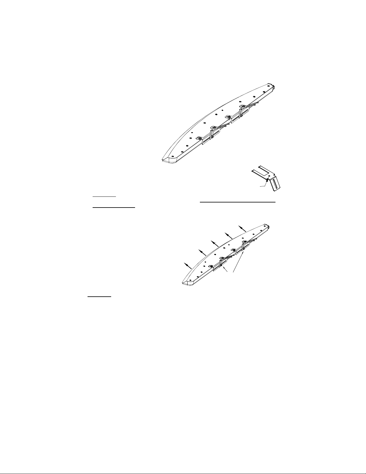
5. Determine an appropriate user-supplied screw to penetrate the
headliner and securely mount the bracket to the roof brace (or other
mounting location) through the mounting hole in each forked bracket.
CAUTION: Take care to ensure when selecting a screw and drilling the hole that it
is capable of supporting the weight of the light and that it does not penetrate the
roof of the vehicle.
Forked Bracket Installation (CONT'D
4. Repeat steps 1-3 for the opposite attaching bracket .
CAUTION: Take extreme caution not to over tighten the screws!!! Over tightening
of the screws can strip the holes.
Tighten the nuts securing
the mounting brackets
Press light tightly
against window
Mounting
Hole
6. Using the slots in the brackets, adjust the
light so that it fits tightly against the window,
carefully bending the forked brackets, if
necessary, and tighten the screws.

-4-
2. Connect one of the double-slotted "L" brackets to one of
the slotted straight brackets using one of the screws, a flat
washer, a tooth washer, and a nut.
4.
Connect one bracket to each end of your
Star
Phantom
®
using the screws provided. Loosen
both screws slightly to allow for adjustability when
installing the lightbar.
3. Repeat this using the other double-slotted "L" bracket
and slotted straight bracket. You should now have two
adjustable "L" mounting brackets.
REAR WINDOW
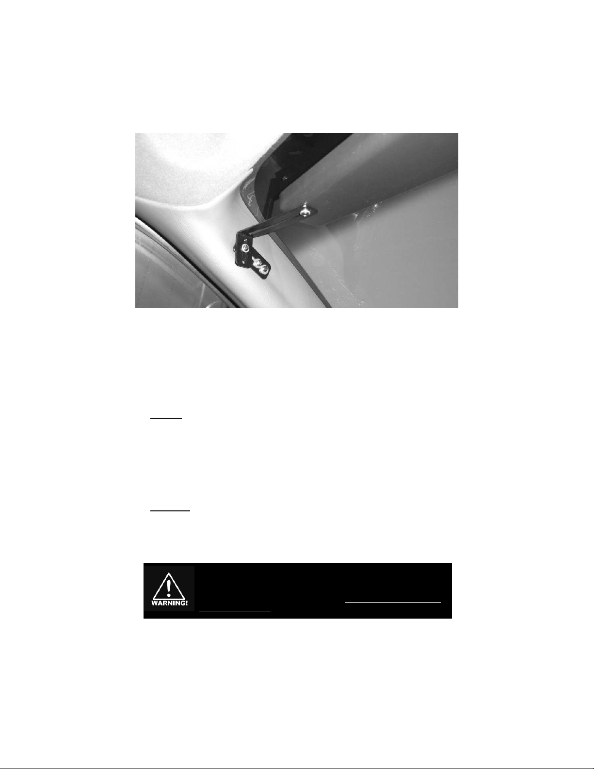
CORNER POST BRACKET INSTALLATION
1. After the forked
brackets are installed,
you will need to attach
the corner post
mounting brackets.
-5-
Because of the wi e variety of mounting applications, Star Hea light
& Lantern Co., Inc. assumes no responsibility for the secure mounting
of this light. It is the responsibility of the installer an /or owner to
ensure the lightbar is mounte securely. Check your light every time
you enter the vehicle to ensure that it is mounte securely.
5. Adjust the mounting brackets so that they rest flat against the corner post on each side
of the vehicle.
6. Once the brackets are adjusted to the desired position, tighten all the screws on the
brackets.
7. Mark the two spots where you will be attaching your screws to the corner post.
8. Loosen the brackets, temporarily slide them aside, and drill a 1/8" hole in each of the
marked locations.
Caution: Be sure to check that there are no wires or anything else behin the mol ing
that may be amage by the screw holes.
9. Return the brackets to their original position against the corner post and use two of the
self-tapping screws in each side to secure each bracket to the corner posts.
10. Once the brackets are securely tightened, check your mount to ensure the desired angle
is achieved. Stand behind the vehicle and inspect the light through the rear window.
The screws may be loosened slightly to allow for any final adjustments necessary.
11. Once all the necessary adjustments are made retighten all the screws.
CAUTION: Take extreme caution not to over tighten the screws!!! Over tightening
of the screws can strip the holes and result in a faulty mount.
Corner Post Bracket Installation (CONT'D

-6-
Wiring
or proper installation and full operability, this light requires a 20A ignition switched power
source, connections to the negative terminal of the battery, and 4-6 external switches rated
for a minimum 1A (user supplie ).
These lights come with a pre-installed 8-conductor harness. In addition, the cable also
contains a bare drain wire and foil shielding.
BLACK
BARE
White w/Brown - TD Warn (or Pursuit/ lashing White Lights)
Green w/Yellow - TD Left (or Takedowns/Steady Burn White)
Yellow - TD Right (or California Title 13 Lights/Steady Red)
Green w/Red - Pattern Select or Dim
Red - Ignition Switched +12VDC
User Supplied Switches
Orange w/Red - Level 2 lashing Warning Lights
Orange w/Green - Level 1 lashing Warning Lights
+12VDC
+12VDC
+12VDC
+12VDC
+12VDC
+12VDC
+-
20 AMP
USE
Quick Wiring Guide
All wires connected to the positive terminal of the battery should be fused at the
battery for their rated load. Testing the light before this fuse is properly
installe will voi the warranty on the light.
Please Note: When the re wire is connecte to +12VDC the light will raw a
small current (2 mA). Occasionally vehicles may sit for exten e
perio s of time (i.e. more than a few ays), thus we recommen that
the re wire be route through an ignition switche power source.
Both = Center-Out Pattern
White w/Brown TD Warn Pattern
Green w/Yellow TD Left
Yellow TD Right
MUST BE CONNECTED

-7-
Programming
Programming is optional. If the default settings
are acceptable, skip to the Operation section.
If you will be changing any of the options on your lightbar, this should be done prior to
installation. Programmable features include the following:
• Traffic Director or Takedown Mode
• Dim Option (High-Low)
• Pattern Selection
• Phase Selection (which heads alternate)
• Head Enable (which heads activate)
• Title 13 Programming
• Pattern Cycling
• Resetting the actory defaults
• Program Mode (Copying all settings from one light to another)
Traffic Director /Takedown
This light has the option to operate in either Traffic Director Mode or Takedown Mode.
By default, standard ULB48-TD lightbars will be shipped with Traffic Director Mode ON
(DOWN in the picture above).
If you will NOT be using the Traffic Director functions of this bar (Warn, Left, Right, and
Center Out) you can move this DIP switch into Takedown Mode (UP) which will replace the
Traffic Director unctions with Pursuit, Takedown, and Title 13 functions.
There are three DIP
switches, two push-button
switches, and a telephone-
style jack, all located on the
top of the light, that should
be used to set any of these
options prior to
installation.
Please Note: A small black
adhesive-backed plastic
plate (P30019-148 ) is
included to cover the
opening once all
programming has been
completed.
ON CTS
123
Program Mo e
High-Low/Pattern
Traffic Director/ Take own
Phase Programming
Hea Enable Programming
Communication Port
High-Low/Pattern Option
This light is equipped with an option allowing you to dim the light for nighttime operation. If
you do not need this feature, skip this section.
The High-Low/Pattern Option switch is used to control the function of the Green w/Red wire.
The Green w/Red wire is normally used for Pattern Programming (see next page). If you
are using the Dim feature, A TER PROGRAMMING YOUR LASH PATTERNS, flip this
switch into the ON position (DOWN in the diagram above). When +12VDC is applied to the
Green w/Red wire, the light will dim.

-8-
Programming (CONT'D
Pattern Programming
Not only does this light have several Patterns to select from, but it also incorporates
advanced programming that allows you to select which heads flash On and Off with one
another (Phase), and which heads are active in any of the functions (Head Enable).
Patterns for Warning Lights
(Level 1, Level 2, an TD Warn/Pursuit)
1 licker *
2 Slow Singleflash
3 ast Singleflash
4 Slow Doubleflash
5 ast Doubleflash
6 Slow Tripleflash
7 ast Tripleflash
(Level 2 efault)
8 Quadflash
9 Quintflash
10 Tripleflash w/Post Pop
11 Quadflash w/Post Pop
12 Quintflash w/Pre Pop
13 Singleflash licker **
14 Doubleflash licker
15 Single, Quad w/Post Pop, licker
16 Delta-Omega
17 Moving Delta-Omega ***
18 Random 1
19 Random 2
20 Random 3
21 lashing Bounce
22 ull Bounce
(Level 1 efault)
23 Split Bounce
24 Half Bounce
25 Bounce w/End Pop
26 Search Lights
27 Eyeballz
28 ade Invert
29 Singleflash w/Alternating Ends
30 Triple In/Triple Out
31 Two Speed
(Pursuit efault)
* Shortcut Pattern #1 (3 sec/1 flash)
** Shortcut Pattern #2 (6 sec/2 flashes)
*** Shortcut Pattern #3 (9 sec/3 flashes)
California Title 13
SAE J595 Approved Patterns
Basic Pattern Selection
The first step in programming is to select a basic pattern for each of the 4 modes:
• Traffic Director Warn Lights (or Pursuit, if applicable)
(White w/Brown)
• Level 1 Warning Lights
(Orange w/Green)
• Level 2 Warning Lights
(Orange w/Re )
• Traffic Directing Patterns (L, C-O, and R)
(Yellow or Green w/Yellow)
1. Connect the Red wire to power and the
Black wire to Ground.
2. Activate the function you wish to
program by connecting the
corresponding wire to +12VDC.
3. Touch and release the Green w/Red
wire to +12VDC to scroll through the
patterns shown to the right. (Traffic
Director L, C-O, R shown below.)
Note: At any time you can shortcut to
the patterns with the asterisks by
hol ing the pattern select wire to
+12VDC for the in icate time.
4. Repeat for each function you wish to
program.
Patterns for Traffic Director
(Left, Right, an Center Out functions
all use the same pattern)
1 Standard *
2 6-Head TD with End lash
3 Standard w/End Blink
4 Two-Head Traveling
5 California Title 13 **
6 California Title 13 ast
7 our Head Traveling
8 Snake
9 Pop
* Shortcut Pattern #1 (3 sec/1 flash)
** Shortcut Pattern #2 (6 sec/2 flashes)
California Title 13
SAE J595 Compliant Patterns
Please note: All California Title 13 and SAE J595 approved patterns need
to be configured properly to ensure compliance with those specifications.

-9-
Phase Selection
(Programmable for Patterns 1-16 only
Each flashing head has two Phases, an “On” phase and an
“Off” phase. You can program each head for either Phase,
allowing you to customize which heads flash On together
and which are Off together. This can be done for your
Level 1, Level 2, and TD Warn functions.
1. Connect the Red wire to power and the Black wire to
Ground.
2. Activate the function you wish to program by connecting
the corresponding wire to +12VDC.
3. Press the Phase
Programming
button to scroll
through the five
optional Phase
variations.
4. Repeat for each function you wish to program.
Programming (CONT'D
Head Enable
This light also has the ability for the installer to select which heads are active for any given
function. You may wish to de-activate several heads in your Level 1 Pattern to indicate less
urgency. Or you may wish to have a 6 or 8 head Traffic Director pattern with the end heads
flashing the Level 1 or 2 patterns. This option can be programmed for any of the functions.
1. Connect the Red wire to power and the Black wire to Ground.
2. Activate the function you
wish to program by
connecting the
corresponding wire to
+12VDC.
3. Press the Head Enable
Programming button to
scroll through the 13
optional variations. (Note:
only options 1-3 are
available for the Traffic
Director Functions.)
4. Repeat for each function you wish to program.
T13 Steady Burn Head
California Title 13 Steady Red Head
If you require California Title 13 compliance, your vehicle requires a Red steady burn light.
To program one of the RED heads for a steady burn mode, proceed as follows:
1. Connect the Red wire to power
and the Black wire to Ground.
2. Activate the California Title 13
function (Yellow wire) and use
the Head Enable button to scroll
through the various positions for
the Red head.
ON CTS
1 2 3
Phase Programming
Hea Enable Programming
Communication
Port
Program Mo e
High-Low/Pattern
Traffic Director/ Take own

-10-
Programming (CONT'D
Pattern Cycling of Simultaneous Functions
This section is OPTIONAL. ‘Pattern Cycling of Simultaneous Functions’ refers to how the
light reacts if you activate more than one function at the same time.
This light is programmed such that when you activate one of the Traffic Directing patterns
(Left, Right, or Center-Out) at the same time as one of the Warning patterns (Level 1
lashing, Level 2 lashing, or TD Warn) they will alternate with the bar producing 3 traffic
directing cycles, then 1 Warning cycle, and repeat (ex: Left, Left, Left, Warn, Left, Left, Left,
Warn, etc.).
If you activate TD Warn with either Level 1 or Level 2 lashing:
If Level 1 or 2 is pattern 1-16: TD Warn lights alternate the Level 1 or 2 Pattern with the
Level 1 or 2 lights.
If Level 1 or 2 is pattern 17-31: TD Warn Lights go into a random Pattern while Level 1 or
Level 2 lights flash in their programmed pattern (page 8).
You may skip the rest of this section if the above settings are acceptable.
Traffic Director Cycle Count refers to the number times the Traffic Directing Pattern
(Right, Left, Center-Out) will repeat before alternating to the Warn/ lashing Pattern. It is
defaulted to 3.
Warn Cycle Count refers to the number times the Level 1 lashing, Level 2 lashing, or TD
Warn pattern will repeat before alternating to the Traffic Directing Pattern (this also applies if
you activate Level 1 or 2 and the TD Warn). It is defaulted to Off (or 0). (Note: if O ,
pattern runs once when cycling with Traffic Director).
1. lip the Program Mode switch onto the ON position (DOWN in the diagram on the
previous page).
2. Connect the Red wire to power and the Black wire to Ground.
3. Program the Traffic Director Cycle Count:
A. Activate the Left function by connecting the Green w/Yellow wire to +12VDC.
(Please note that the Left, Right, an Center-Out will all have the same Cycle Count
an can be programme using any one of those functions.)
One of the heads (or none) will illuminate indicating what the current Traffic
Director Cycle Count is.
Ex: If no hea s are lit, the feature is off. (Default setting Warning Patterns)
If Hea 1 is lit, that mo e is programme to cycle 1 time.
If Hea 2 is lit, that mo e is programme to cycle 2 times.
If Hea 3 is lit, that mo e is programme to cycle 3 times (Default setting
for Traffic Director Patterns)
an so on through Hea 10.
B. Touch and release the Green w/Red wire to +12VDC to scroll through the different
Cycle Counts.
4. Repeat step 3 using the White w/Brown wire to program the Warn Cycle Count. (Please
note that Level 1 Flashing, Level 2 Flashing, an TD Warn will all have the same Cycle
Count an can be programme using any one of those functions.)
5. Disconnect all wires and flip the corresponding DIP switch out of Programming Mode.

-11-
Program Mode (Cloning
If you are installing multiple lights and have a number of
options to set, you may find it easier to set up one light,
then “clone” its settings onto the other lights. To do so,
proceed as follows:
1. Program the first light as described.
2. Connect the second light to the programmed unit using
a special telephone-type cable (P/N SWH-140 available
from the manufacture upon request) between the two
communications ports.
3. lip the Program Mode switches from both lights onto the ON position (DOWN in the
diagram above). Both lights should start flashing all Traffic Director lights.
4. Press the Phase button on the light you would like to reprogram and hold it until the
Traffic Director (or Pursuit) lights go off and the colored lights start flashing. Release the
button and the new programming information will begin uploading to the second unit.
Once it has successfully completed uploading all of the programming, the entire light will
illuminate into a steady burn mode. Repeat programming if not.
5. lip the Program Mode DIP switches from both lights into the O position and remove
the cable connecting the lights. Programming should be completed.
Programming (CONT'D
O N C T S
123
Phase
Hea Enable
Communication
Program Mo e
High-Low/Pattern
Traffic Director/ Take own
Resetting to Factory Default Settings
1. Connect the Red wire to power and the Black wire to Ground.
2. lip the Program Mode switch ON position (DOWN in the diagram above). All Traffic
Director (or Pursuit) lights should start flashing.
3. Press and hold the Head Enable button until the Traffic Director (or Pursuit) lights go off
and all of the heads light up sequentially from left to right.
4. Once all of the heads are illuminated, release the Head Enable button and the light will
be restored to the factory default settings.
5. lip the Program Mode DIP switch into the O position.

-12-
Operating Instructions
Functions Switched Through Wires
Main control of this light is done though the wires in the harness. They should be connected
to +12VDC through several switches (user supplie ) as described in the Wiring section.
TD Warn
(White w/Brown)
Usually activated when a vehicle has been pulled over. The amber lights will flash in the
WARN pattern you have them programmed for.
Level 1 lashing Mode
(Orange w/Green)
This is usually intended as a slower, less urgent mode typically used when parked.
Level 2 lashing Mode
(Orange w/Red)
This mode is intended for high-urgency situations, such as a high speed chase, requiring
significant warning power. It is usually a faster pattern than Level 1.
The Level 2 pattern will override Level 1 lights.
TD Left
(Green w/Yellow)
Applying +12VDC to this wire will produce a pattern directing traffic left.
TD Right
(Yellow)
Applying +12VDC to this wire will produce a pattern directing traffic right.
Center-Out
(Green w/Yellow)
and (Yellow)
Applying +12VDC to BOTH of these wires will produce the Center-Out Pattern.
Dim Option
DIM
(Green w/Red)
If the High-Low/Pattern Option is set for High-Low (see page 7), then applying +12VDC
will dim the light (typically used in nighttime applications).
Activation of Multiple Functions
Depending upon programming, the light will have different outputs when multiple functions
(i.e. switches) are activated at the same time. Please review Pattern Cycling of
Simultaneous Functions on page 10 to determine how your light is programmed.
NOTE: RED MUST BE CONNECTED TO POWER
BLACK MUST BE CONNECTED TO GROUND

-13-
If you have any questions concerning this or any other product, please contact our
Customer Service Department at (585) 226-9787.
If a product must be returned for any reason, please contact our
Customer Service Department to obtain a Returned Materials Authorization
number (RMA #) before you ship the product back.
Please write the RMA # clearly on the package near the mailing label.
LED FIVE YEAR LIMITED WARRANTY
The manufacturer warrants this LED light against factory defects in material and workmanship for five years
after the date of purchase. The owner will be responsible for returning to the Service Center any defective
item(s with the transportation costs prepaid. The manufacturer will, without charge, repair or replace at its
option, products, or part(s , which its inspection determines to be defective. Repaired or replacement
item(s will be returned to the purchaser with transportation costs prepaid from the service point. A copy of
the purchaser's receipt must be returned with the defective item(s in order to qualify for the warranty
coverage. Exclusions from this warranty include, but are not limited to, domes, and/or the finish. This
warranty shall not apply to any light, which has been altered, such that in the manufacturer's judgment, the
performance or reliability has been affected, or if any damage has resulted from abnormal use or service.
There are no warranties expressed or implied (including any warranty of merchantability or fitness , which
extend this warranty period. The loss of use of the product, loss of time, inconvenience, commercial loss or
consequential damages, including costs of any labor, are not covered. The manufacturer reserves the right
to change the design of the product without assuming any obligation to modify any product previously
manufactured.
This warranty gives you specific legal rights. You might also have additional rights that may vary from state to
state. Some states do not allow limitations on how long an implied warranty lasts. Some states do not allow
the exclusion or limitation of incidental or consequential damages. Therefore, the above limitation(s or
exclusion(s may not apply to you.

-14-
NOTICE
Due to continuous product improvements, we must reserve the right to change any
specifications and information, contained in this manual at any time without notice.
Star Headlight & Lantern Co., Inc. makes no warranty of any kind with regard to this
manual, including, but not limited to, the implied warranties of merchantability and
fitness for a particular purpose. Star Headlight & Lantern Co., Inc. shall not be liable
for errors contained herein or for incidental or consequential damages in connection
with the furnishing, performance, or use of this manual.

-15-
Table of contents
Popular Home Lighting Accessories manuals by other brands

LIVARNO home
LIVARNO home 864-R manual

Home Accents Holiday
Home Accents Holiday TY759-1614-0 Use and care guide

MELINERA
MELINERA 277671 Operation and safety notes

Goobay
Goobay 49868 user manual

Somogyi Elektronic
Somogyi Elektronic home NLT 3 instruction manual

Tekky
Tekky SMILING JACK GREETER Installation and operating instructions


