Star Lake INS8346B User manual

INS8346B
Mini ITX Industrial Motherboard
User’s Manual

Safety Information
1. Electrical safety
•To prevent electrical shock hazard, disconnect the power cable from the electrical outlet before
relocating the system.
•When adding or removing devices to or from the system, ensure that the power cables for the devices
are unplugged before the signal cables are connected. If possible, disconnect all power cables from the
existing system before you add a device.
•Before connecting or removing signal cables from the motherboard, ensure that all power cables are
unplugged.
•Seek professional assistance before using an adapter or extension cord. These devices could interrupt
the grounding circuit.
•Make sure that your power supply is set to the correct voltage in your area.
•If you are not sure about the voltage of the electrical outlet you are using, contact your local power
company.
•If the power supply is broken, do not try to fix it by yourself. Contact a qualified service technician or
your local distributor.
2. Operation safety
•Before installing the motherboard and adding devices on it, carefully read all the manuals that came
with the package.
•Before using the product, make sure all cables are correctly connected and the power cables are not
damaged. If you detect any damage, contact your dealer immediately.
•To avoid short circuits, keep paper clips, screws, and staples away from connectors, slots, sockets and
circuitry.
•Avoid dust, humidity, and temperature extremes. Do not place the product in any area where it may
become wet.
•Place the product on a stable surface.
•If you encounter any technical problems with the product, contact your local distributor
Statement
•All rights reserved. No part of this publication may be reproduced in any form or by any means, without
prior written permission from the publisher.
•All trademarks are the properties of the respective owners.
•All product specifications are subject to change without prior notice
1

Revision History
Revision
Date (yyyy.mm.dd)
Changes
Version 1.0
2014.10.14
Initial release
Packing list
□INS8346B Mini-ITX Industrial MB
□1 x I/O shield
□1 x SATA cable
□2 x COM cables with bracket
□1 x USB cable
□CD (Driver+ user’s manual)
Optional Accessories
•Cable Kit: Audio cable, PS/2 cable
•Thermal Kit: CPU cooler
•Processor:
Intel® Core™ i7-3770 (8M Cache, 3.40 GHz), 77W
Intel® Core™ i5-3550S (6M Cache, up to 3.70 GHz), 65W
Intel® Core™ i3-3220 (3M Cache, 3.30 GHz), 55W
Intel® Pentium® G2120 (3M Cache, 3.10 GHz), 55W
Intel® Core™ i7-2600 (8M Cache, 3.40 GHz), 95W
Intel® Core™ i5-2400 (6M Cache, 3.10 GHz), 95W
Intel® Core™ i3-2120 (3M Cache, 3.30 GHz), 65W
Intel® Pentium® G850 (3M Cache, 2.90 GHz), 65W
Intel® Celeron® G540 (2M Cache, 2.50 GHz), 65W
If any of the above items is damaged or missing, please contact your
local distributor.
Ordering Information
Part Number
Description
INS8346B-ET
Intel® Ivy Bridge Q77 Mini-ITX Industrial MB, -20 to 70°C
INS8346B-UT
Intel® Ivy Bridge Q77 Mini-ITX Industrial MB, -40 to 85°C
2

Table of Contents
SAFETY INFORMATION
................................................................................................................................................................. 1
1. ELECTRICAL SAFETY .......................................................................................................................................................................... 1
2. OPERATION SAFETY .......................................................................................................................................................................... 1
STATEMENT
................................................................................................................................................................................. 1
REVISION HISTORY
....................................................................................................................................................................... 2
PACKING LIST
............................................................................................................................................................................... 2
OPTIONAL ACCESSORIES
............................................................................................................................................................... 2
ORDERING INFORMATION
............................................................................................................................................................ 2
TABLE OF CONTENTS
.................................................................................................................................................................... 3
CHAPTER 1: PRODUCT INFORMATION
........................................................................................................................................... 6
1.1 BLOCK DIAGRAM ........................................................................................................................................................................... 6
1.2 KEY FEATURES............................................................................................................................................................................... 7
1.3 BOARD PLACEMENT ....................................................................................................................................................................... 9
1.4 MECHANICAL DRAWING................................................................................................................................................................ 10
CHAPTER 2: JUMPERS AND CONNECTORS
................................................................................................................................... 11
2.1 JUMPERS AND CONNECTORS LIST..................................................................................................................................................... 11
2.2 JUMPER SETTINGS........................................................................................................................................................................ 13
HDMI: HDMI Connector ........................................................................................................................................................... 13
VGA+DVI1: VGA Connector + DVI-D Connector ........................................................................................................................ 13
LAN1_USB12: LAN & USB3.0 Port Connector ........................................................................................................................... 14
LAN2_USB34: LAN & USB3.0 Port Connector ........................................................................................................................... 14
AUDIO1: 3 Stack-up HD Audio Phone Jack ............................................................................................................................... 14
PCIEX16_1: Standard PCI Express x16 Slot ............................................................................................................................... 15
ATX_20P: 20 pin ATX Power Input Connector ........................................................................................................................... 16
ATX12V1: 4 pin ATX Power Input Connector ............................................................................................................................. 16
MPCIE_CARD1: Mini PCIE connector........................................................................................................................................ 16
MSATA_CARD1: MSATA CARD connector.................................................................................................................................. 17
CPUFAN: CPU FAN Wafer ......................................................................................................................................................... 17
SYSFAN1: System FAN Wafer .................................................................................................................................................... 17
SYSFAN2: System FAN Wafer .................................................................................................................................................... 18
KB_MS: PS2 KB/MS .................................................................................................................................................................. 18
FP1: Front Panel 1 .................................................................................................................................................................... 18
JBKL1: Inverter connector......................................................................................................................................................... 18
3

JP3: BL_EN Level SELECT .......................................................................................................................................................... 19
JP3: BL_ADJ MODE SELECT....................................................................................................................................................... 19
LVDS: LVDS connector............................................................................................................................................................... 20
JP4: LVDS_VDD power select .................................................................................................................................................... 20
COM6: RS232 ........................................................................................................................................................................... 21
COM3: RS232 ........................................................................................................................................................................... 21
COM4: RS232 ........................................................................................................................................................................... 21
COM5: RS232 ........................................................................................................................................................................... 21
F_USB2: USB2.0 port 2,3 pin header ........................................................................................................................................ 22
F_USB1: USB2.0 port 0,1 pin header........................................................................................................................................ 22
DIO1: Digital input/output pin header...................................................................................................................................... 22
DIO2: Digital input/output pin header...................................................................................................................................... 23
JP6: DIO1_PWR Level SELECT ................................................................................................................................................... 23
JP6: DIO2_PWR Level SELECT ................................................................................................................................................... 24
SATA1, SATA2: Serial ATA 3.0 Connector ................................................................................................................................... 24
SATA3, SATA4: Serial ATA 2.0 Connector ................................................................................................................................... 24
DIMMA1, DIMMB1: DDR3 SO-DIMM connector ...................................................................................................................... 25
JP2: COM2 +12V/+5V selection ................................................................................................................................................ 25
JP1: COM1 +12V/+5V selection ................................................................................................................................................ 25
COM1: RS232/422/485 with +12V/+5V selection..................................................................................................................... 25
COM2: RS232/422/485 with +12V/+5V selection..................................................................................................................... 26
FP3: FRONT LAN LED................................................................................................................................................................ 26
AFP1: LINE-OUT/MIC-IN ........................................................................................................................................................... 26
JCASE1: Case Open Warning .................................................................................................................................................... 26
ME_DIS: Flash Descriptor Security Overide/ Intel ME Debug Mode.......................................................................................... 27
CLR_CMOS: RTC Reset .............................................................................................................................................................. 27
BAT1: RTC battery connector.................................................................................................................................................... 27
PSON1: ATX/AT mode ............................................................................................................................................................... 27
DEBUG: Debug card connector ................................................................................................................................................ 28
JP7: LVDS Panel selection ......................................................................................................................................................... 28
JP7: LVDS Panel selection jumper setting ................................................................................................................................. 29
CHAPTER 3: AMI BIOS UTILITY
..................................................................................................................................................... 30
3.1 STARTING................................................................................................................................................................................... 30
3.2 NAVIGATION KEYS........................................................................................................................................................................ 30
3.3 MAIN MENU .............................................................................................................................................................................. 31
3.4 ADVANCED MENU ....................................................................................................................................................................... 33
3.4.1 ACPI Settings ................................................................................................................................................................... 34
3.4.2 CPU Configuration........................................................................................................................................................... 35
4

3.4.3 SATA Configuration.......................................................................................................................................................... 37
3.4.4 Thermal Configuration .................................................................................................................................................... 41
3.4.5 Intel Rapid Start Technology............................................................................................................................................ 43
3.4.6 PCH-FW Configuration .................................................................................................................................................... 44
3.4.7 Intel Anti-Theft Technology Configuration ....................................................................................................................... 46
3.4.8 AMT Configuration.......................................................................................................................................................... 47
3.4.9 Acoustic Management Configuration.............................................................................................................................. 49
3.4.10 USB Configuration......................................................................................................................................................... 50
3.4.11 SMART Settings ............................................................................................................................................................. 51
3.4.12 IT8786 Super IO Configuration ...................................................................................................................................... 52
3.4.13 IT8786 H/W Monitor..................................................................................................................................................... 53
3.4.14 Platform Misc Configuration ......................................................................................................................................... 54
3.4.15 Intel SMART Connect Technology .................................................................................................................................. 55
3.4.16 WatchDog Timer Configuration .................................................................................................................................... 56
3.4.17 Serial Port Console Redirection...................................................................................................................................... 57
3.4.18 Intel ICC ......................................................................................................................................................................... 59
3.4.19 Network Stack ............................................................................................................................................................... 60
3.4.20 Intel RC Drivers Version Detail ....................................................................................................................................... 61
3.4.21 CPU PPM configuration................................................................................................................................................. 62
3.4.22 Switchable Graphics ...................................................................................................................................................... 63
3.4.23 Intel(R) 82579LM Gigabit Network Connection............................................................................................................. 64
3.4.24 Intel(R) 82574L Gigabit Network Connection ................................................................................................................ 65
3.5 CHIPSET..................................................................................................................................................................................... 66
3.5.1 PCH-IO Configuration...................................................................................................................................................... 67
3.5.1.1 PCI Express Configuration.............................................................................................................................................................69
3.5.1.2 USB Configuration ........................................................................................................................................................................74
3.5.1.3 PCH Azalia Configuration..............................................................................................................................................................75
3.5.1.4 BIOS Security Configuration..........................................................................................................................................................76
3.5.2 System Agent (SA) Configuration .................................................................................................................................... 77
3.5.2.1 Graphics Configuration: Config Graghics Settings.........................................................................................................................78
3.5.2.2 DMI Configuration........................................................................................................................................................................81
3.5.2.3 NB PCIe Configuration ..................................................................................................................................................................82
3.5.2.4 Memory Configuration .................................................................................................................................................................84
3.5.2.5 Memory Thermal Configuration ...................................................................................................................................................86
3.5.2.6 GT-Power Management Control...................................................................................................................................................87
3.6 BOOT ........................................................................................................................................................................................ 88
3.7 SECURITY ................................................................................................................................................................................... 89
3.8 SAVE AND EXIT ............................................................................................................................................................................ 91
5
Chapter 1: Product Information
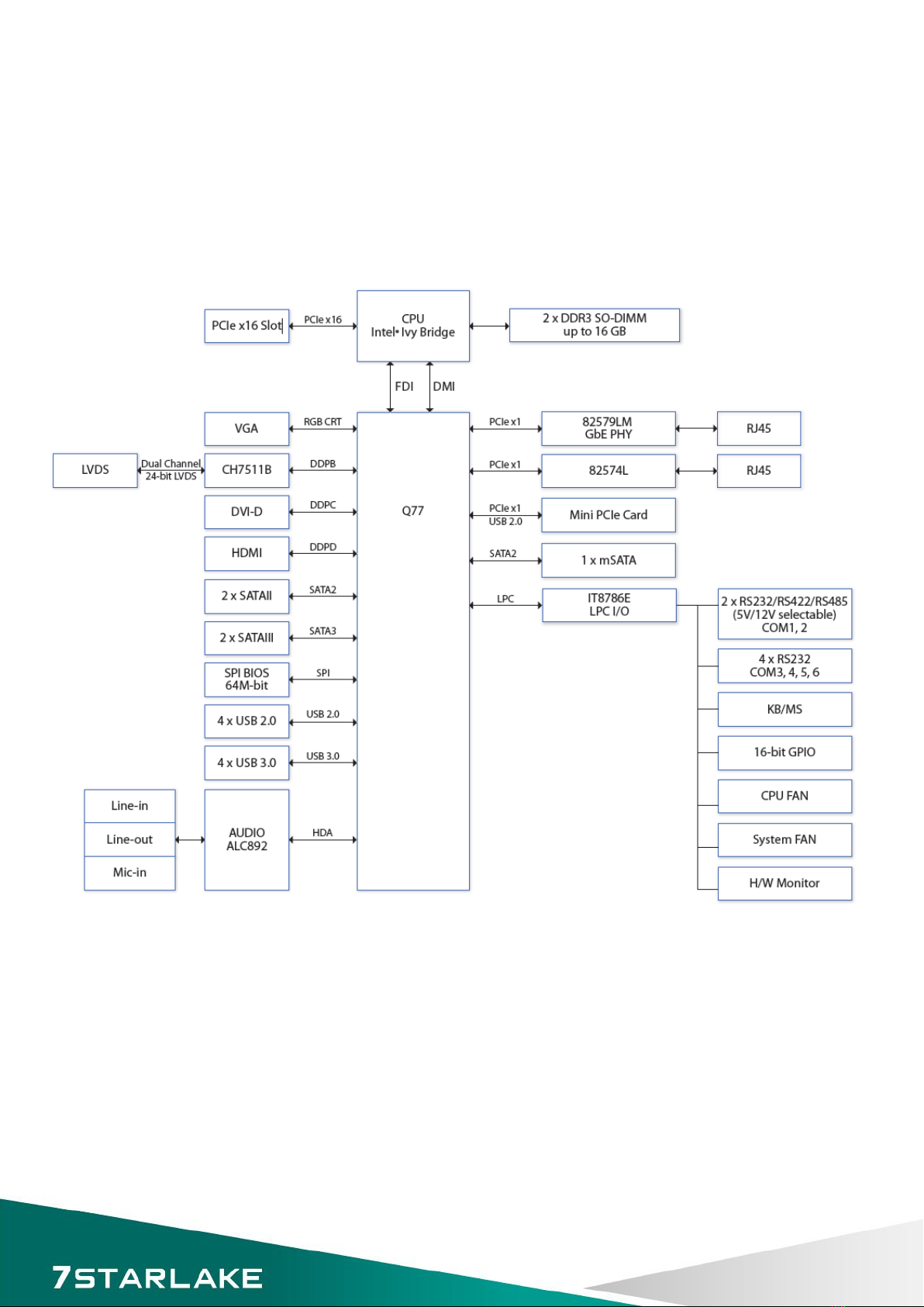
1.1 Block Diagram
6
1.2 Key Features
System
CPU Type
Intel® LGA1155 Core™ i7/i5/i3 Processor
Core™ i7-3770 3.4 GHz (8M Cache, 95W)
Core™ i5-3550S 3.0 GHz (6M Cache, 65W)
Core™ i3-3220 3.3 GHz (3M Cache, 65W)
Pentium® G2120 3.1 GHz (3M Cache, 65W)
Chipset
Intel® Q77
Memory Type
2 x 204-pin SO-DIMM DDR3 1333/1600 MHz up to 16 GB
BIOS
AMI® UEFI BIOS
Supoer I/O
ITE8786E
iAMT
Support iAMT 8.0
Watchdog
1-255 sec. or 1-255 min. software programmable,
can generate system reset
Expansion Slot
1 x PCIe x16 Gen.2
1 x mPCIe
1 x mSATA
Display
Chipset
Intel® HD Grapics 4000 Integrated Graphics Engine
LVDS
Dual channel 24-bit LVDS
Display Type
VGA, LVDS, DVI, HDMI
Audio
Codec
Realtek ALC892 High Definition Audio Codec
Ethernet
Chipset
Intel® 82579LM & 82574L GbE
WOL
Yes
Boot from LAN
Yes for PXE
Rear I/O
VGA
1
DVI-D
1
HDMI
1
Ethernet
2 x RJ45
Audio
Mic-in, Line-in, Line-out
COM Port
2 x RS232/422/485 with 5V/12V selectable
USB
4 x USB 3.0
Internal I/O
SATA
2 x SATAIII (6 Gb/s)
2 x SATAII (3 Gb/s)
USB
4 x USB 2.0 ports by pin header
COM
4 x RS232 ports: COM3~6 support RS232 by pin header
DIO
16-bit (8 in/8 out)
LVDS
1
PS/2
1
Fan
1 x CPU fan
2 x System fan connector
7

Mechanical and Environment
Form Factor
Mini-ITX Industrial MB
Power Type
ATX (20-pin + 4-pin)
Dimension
170 x 170 mm (6.7” x 6.7”)
Operating Temp.
-40 to 85°C
Relative Humidity
10% to 90%, non-condensing
*All specifications and photos are subject to change without notice.
8

1.3 Board Placement
9
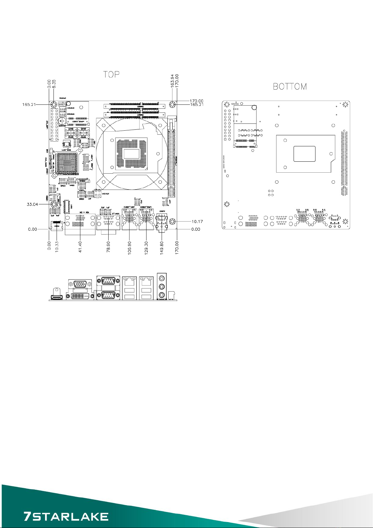
1.4 Mechanical Drawing
10

Chapter 2: Jumpers and Connectors
2.1 Jumpers and connectors list
Jumper
Connector
Description
Type
Function
Others
CLR_CMOS
Pin Header
ME_DIS Pin Header
PSON1 Pin Header
ATX12V1 Power
ATX_20P Power
CPU1 Socket CPU
DIMMA1 Slot DIMM
DIMMB1
PCIEX16_1 Slot PCIE
SATA1 SATA 3
SATA2
SATA3 SATA 2
SATA4
VGA+DVI1 VGA 15Pin D-SUB VGA
DVI
HDMI HDMI
JCASE1
JP6 DIO1 Pin Header
DIO DIO Port 0~3
DIO2 DIO Port 4~7
KB_MS Pin Header
P/S2 Key Board
P/S2 Mouse
FP1 Pin Header
Front Panel
Front Panel
F_USB1 Pin Header
USB 2.0 Front Panel 1st. USB 2.0
F_USB2 Front Panel 2nd. USB 2.0
CPUFAN
FAN
4Pin CPU FAN
SYSFAN1 3Pin System FAN
SYSFAN2
AUDIO1 Audio
11

Jumper
Connector
Description
Type
Function
Other
AFP1 Pin Header
Audio Front Panel Audio
JP1 COM1_2
COM
RS232/422/485
JP2
COM3
Pin Header
RS232
COM4
COM5
COM6
mPCIE_CARD1
mSATA_CARD1
JP3 JBKL1
LVDS
LVDS Back Light
JP4 LVDS LVDS Panel
JP7
LAN1_USB12
USB 3.0 1st. USB 3.0
USB 3.0 2nd. USB 3.0
Giga LAN 1st. Giga LAN
FP3 Pin Header
Front Panel
Front Panel LAN1~2 LED
LAN2_USB34
Giga LAN 2nd. Giga LAN
USB 3.0 3rd. USB 3.0
USB 3.0 4th. USB 3.0
DEBUG Debug RD Debug Only
12

2.2 Jumper Settings
HDMI: HDMI Connector
PIN
DEFINITION
PIN
DEFINITION
1
HDMI_2P
11
GND
2
GND
12
HDMI_CLKN
3
HDMI_2N
13
NC
4
HDMI_1P
14
NC
5
GND
15
HDMI_CLK
6
HDMI_1N
16
HDMI_DAT
7
HDMI_0P
17
GND
8
GND
18
+5V
9
HDMI_0N
19
HDMI_DET
10
HDMI_CLKP
VGA+DVI1: VGA Connector + DVI-D Connector
VGA
DVI
PIN
DEFINITION
PIN
DEFINITION
PIN
DEFINITION
PIN
DEFINITION
1
RED
9
+5V
1
TMDS2-
13
NC
2
GREEN
10
GND
2
TMDS2+
14
+5V
3
BLUE
11
NC
3
GND
15
GND
4
NC
12
DDC DATA
4
NC
16
HOTPLUG_DETECT
5
GND
13
HSYNC
5
NC
17
TMDS0-
6
GND
14
VSYNC
6
DDC_CLK
18
TMDS0+
7
GND
15
DDC CLOCK
7
DDC_DATA
19
GND
8
GND
8
NC
20
NC
9
TMDS1-
21
NC
10
TMDS1+
22
GND
11
GND
23
TMDSCLK+
12
NC
24
TMDSCLK-
13
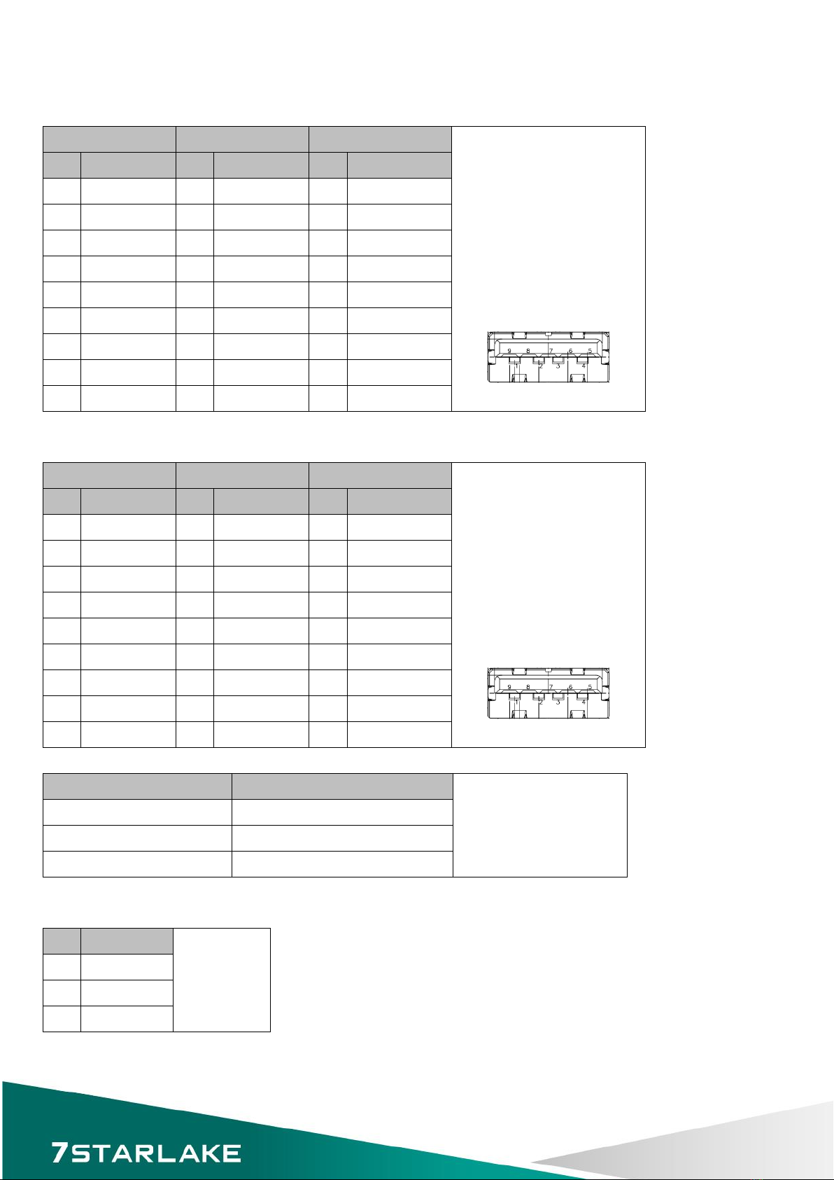
LAN1_USB12: LAN & USB3.0 Port Connector
UPPER USB
LOWER USB
LAN
PIN
DEFINITION
PIN
DEFINITION
PIN
DEFINITION
1 USB3_VCC1 1 USB3_VCC2 1 LAN1_MDI0+
2 USBD0- 2 USBD1- 2 LAN1_MDI0-
3 USBD0+ 3 USBD1+ 3 LAN1_MDI1+
4 GND 4 GND 4 LAN1_MDI1-
5 USB3RN1 5 USB3RN2 5 LAN1_MDI2+
6 USB3RP1 6 USB3RP2 6 LAN1_MDI2-
7 GND 7 GND 7 LAN1_MDI3+
8 USB3TN1 8 USB3TN2 8 LAN1_MDI3-
9 USB3TP1 9 USB3TP2
LAN2_USB34: LAN & USB3.0 Port Connector
UPPER USB
LOWER USB
LAN
PIN
DEFINITION
PIN
DEFINITION
PIN
DEFINITION
1 USB3_VCC3 1 USB3_VCC4 1 LAN2_MDI0+
2 USBD2- 2 USBD3- 2 LAN2_MDI0-
3 USBD2+ 3 USBD3+ 3 LAN2_MDI1+
4 GND 4 GND 4 LAN2_MDI1-
5 USB3RN3 5 USB3RN4 5 LAN2_MDI2+
6 USB3RP3 6 USB3RP4 6 LAN2_MDI2-
7 GND 7 GND 7 LAN2_MDI3+
8 USB3TN3 8 USB3TN4 8 LAN2_MDI3-
9 USB3TP3 9 USB3TP4
SPEED LED: (Lift)
ACTIVE LED: (Right)
GREEN: 1000Mbps ORANGE (BLINKING): ACTIVITY
ORANGE: 100Mbps No Light: NOT LINK
No Light: 10Mbps ORANGE (NO BLINKING): LINK
AUDIO1: 3 Stack-up HD Audio Phone Jack
PIN
DEFINITION
1 LINE-IN
2 LINE-OUT
3 MIC-IN
14
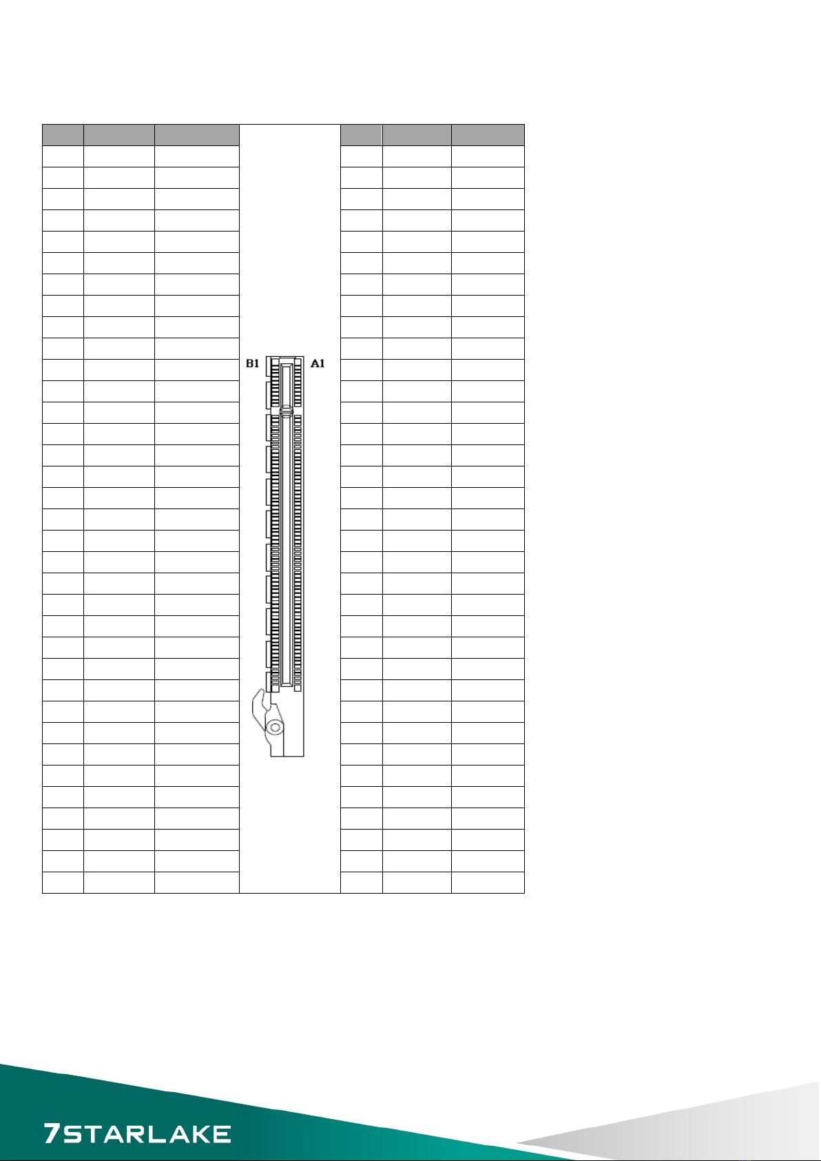
PCIEX16_1: Standard PCI Express x16 Slot
PIN
SIDE B
SIDE A
PIN
SIDE B
SIDE A
1
+12V
PRSNT#(B)
35
Ground
HSIP4
2
+12V
+12V
36
Ground
HSIP4
3
+12V
+12V
37
HSOP5
Ground
4
Ground
Ground
38
HSON5
Ground
5
SMCLK
JTAG2
39
Ground
HSIP5
6
SMDAT
JTAG3
40
Ground
HSIP5
7
Ground
JTAG4
41
HSOP6
Ground
8
+3.3V
JTAG5
42
HSON6
Ground
9
JTAG1
+3.3V
43
Ground
HSIP6
10
+3VSB
+3.3V
44
Ground
HSIP6
11
WAKE#
PWRGD
45
HSOP7
Ground
12
Reserved
Ground
46
HSON7
Ground
13
Ground
REFCLK+
47
Ground
HSIP7
14
HSOP0
REFCLK-
48
PRSNT#3
HSIP7
15
HSON0
Ground
49
Ground
Ground
16
Ground
HSIP0
50
HSOP8
Reserved
17
PRSNT#1
HSIP0
51
HSON8
Ground
18
Ground
Ground
52
Ground
HSIP8
19
HSOP1
Reserved
53
Ground
HSIP8
20
HSON1
Ground
54
HSOP9
Ground
21
Ground
HSIP1
55
HSON9
Ground
22
Ground
HSIP1
56
Ground
HSIP9
23
HSOP2
Ground
57
Ground
HSIP9
24
HSON2
Ground
58
HSOP10
Ground
25
Ground
HSIP2
59
HSON10
Ground
26
Ground
HSIP2
60
Ground
HSIP10
27
HSOP3
Ground
61
Ground
HSIP10
28
HSON3
Ground
62
HSOP11
Ground
29
Ground
HSIP3
63
HSON11
Ground
30
Reserved
HSIP3
64
Ground
HSIP11
31
PRSNT#2
Ground
65
Ground
HSIP11
32
Ground
Reserved
66
HSOP12
Ground
33
HSOP4
Reserved
67
HSON12
Ground
34
HSON4
Ground
68
Ground
HSIP12
69
Ground
HSIP12
15

ATX_20P: 20 pin ATX Power Input Connector
PIN
DEFINITION
PIN
DEFINITION
1
+3.3V
11
+3.3V
2
+3.3V
12
-12V
3
GND
13
GND
4
+5V
14
PS_ON
5
GND
15
GND
6
+5V
16
GND
7
GND
17
GND
8
POWER OK
18
N/C
9
+5VSB
19
5V
10
+12V
20
5V
ATX12V1: 4 pin ATX Power Input Connector
PIN
DEFINITION
PIN
DEFINITION
1 GND 3 +12V
2 GND 4 +12V
MPCIE_CARD1: Mini PCIE connector
PIN
DEFINITION
PIN
DEFINITION
1
-PCIE_WAKE
2
3.3VAUX
3
NC
4
GND
5
NC
6
1.5V
7
mPCIE_REQ#
8
NC
9
GND
10
NC
11
CLK_mPCIE_DN
12
NC
13
CLK_mPCIE_DP
14
NC
15
GND
16
NC
17
NC
18
GND
19
NC
20
-MCARD_DISABLE
21
GND
22
-RST_DB_MINI
23
mPCIE_RXN
24
3.3Vaux
25
mPCIE_RXP
26
GND
27
GND
28
1.5V
29
GND
30
SMB_CLK
31
mPCIE_TXN
32
SMB_DATA
33
mPCIE_TXP
34
GND
35
GND
36
-USB_MINI
37
GND
38
+USB_MINI
39
+3.3VAUX
40
GND
41
+3.3VAUX
42
NC
43
GND
44
NC
45
CL_CLK
46
NC
47
CL_DATA
48
1.5V
49
-CL_RST
50
GND
51
-MCARD_DISABLE
52
3.3VAUX
16
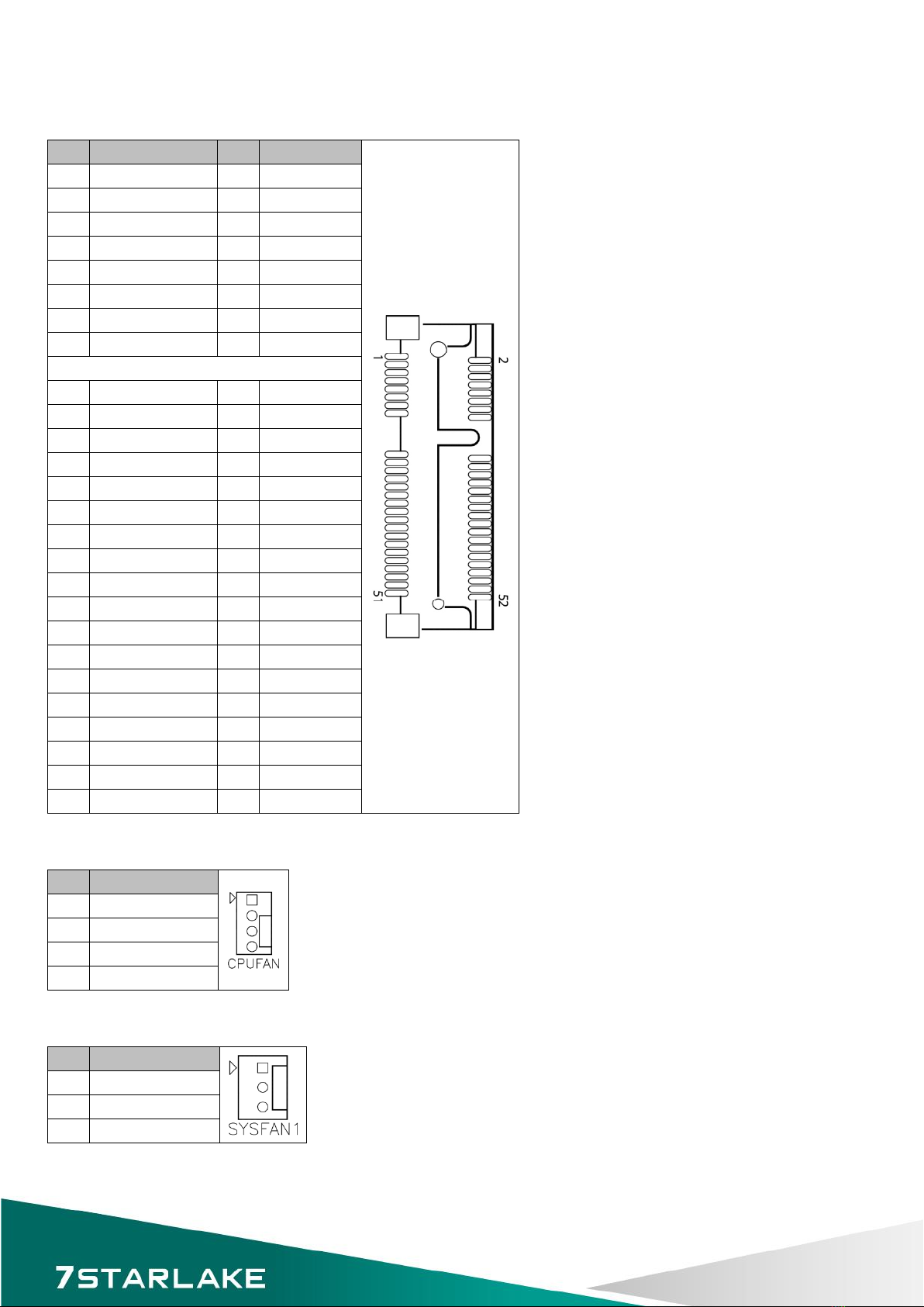
MSATA_CARD1: MSATA CARD connector
PIN
DEFINITION
PIN
DEFINITION
1
NC
2
3.3VAUX
3
NC
4
GND
5
NC
6
+1.5V
7
NC
8
NC
9
GND
10
NC
11
NC
12
NC
13
NC
14
NC
15
GND
16
NC
KEY
17
NC
18
GND
19
NC
20
NC
21
GND
22
NC
23
MSATA_RXP_C
24
3.3VAUX
25
MSATA_RXN_C
26
GND
27
GND
28
1.5V
29
GND
30
NC
31
MSATA_TXN_C
32
NC
33
MSATA_TXP_C
34
GND
35
GND
36
NC
37
GND
38
NC
39
+3.3VAUX
40
GND
41
+3.3VAUX
42
NC
43
GND
44
NC
45
NC
46
NC
47
NC
48
1.5V
49
NC
50
GND
51
NC
52
3.3VAUX
CPUFAN: CPU FAN Wafer
PIN
DEFINITION
1
PWM_CPUFAN
2
TACH_CPUFAN
3
CPUFAN_VCC
4
GND
SYSFAN1: System FAN Wafer
PIN
DEFINITION
1
TACH_SYSFAN1
2
SYSFAN1_VCC
3
GND
17

SYSFAN2: System FAN Wafer
PIN
DEFINITION
1
TACH_SYSFAN2
2
SYSFAN2_VCC
3
GND
KB_MS: PS2 KB/MS
PIN
DEFINITION
PIN
DEFINITION
1
+5VAUX
2
GND
3
4
GND
5
MS DATA
6
KB DATA
7
MS CLOCK
8
KB CLOCK
FP1: Front Panel 1
PIN
DEFINITION
PIN
DEFINITION
1
HDLED+
2
PLED+
3
-SATALED
4
PLED-
5
GND
6
-PWRBTN
7
-SYS_RST
8
GND
9
NC
JBKL1: Inverter connector
PIN
DEFINITION
1
Backlight power (+12V)
2
Backlight power (+12V)
3
Backlight power (+12V)
4
+5V
5
+5V
6
GND
7
GND
8 Backlight_EN
(Voltage level Select by JP3)
9
Backlight_ADJ
(Voltage level Select by JP3)
10
GND
18

JP3: BL_EN Level SELECT
JUMPER
FUNCTION DESCRIPTION
SETTING
5-3 5V
1-3 3.3V
Default setting is 1-3
JP3: BL_ADJ MODE SELECT
JUMPER
FUNCTION DESCRIPTION
SETTING
2-4 PWM mode
6-4 DAC mode
Default setting is 2-4
19
Table of contents
Other Star Lake Motherboard manuals


