Star Lake INS8367A User manual

User’s Manual
Revision Date: Sep. 01. 2023
INS8367A
Intel® Raptor Lake-S/ Alder Lake-S
13th/12th Processor With H610/Q670
Chipset Mini-ITX

INS8367A User’s Manual V1.1
Revision Date: Sep. 01. 2023
1
Safety Information
Electrical safety
To prevent electrical shock hazard, disconnect the power cable from the electrical outlet before
relocating the system.
When adding or removing devices to or from the system, ensure that the power cables for the
devices are unplugged before the signal cables are connected. If possible, disconnect all
power cables from the existing system before you add a device.
Before connecting or removing signal cables from the motherboard, ensure that all power
cables are unplugged.
Seek professional assistance before using an adapter or extension cord. These devices could
interrupt the grounding circuit.
Make sure that your power supply is set to the correct voltage in your area.
If you are not sure about the voltage of the electrical outlet you are using, contact your local
power company.
If the power supply is broken, do not try to fix it by yourself. Contact a qualified service
technician or your local distributor.
Operation safety
Before installing the motherboard and adding devices on it, carefully read all the manuals that
came with the package.
Before using the product, make sure all cables are correctly connected and the power cables
are not damaged. If you detect any damage, contact your dealer immediately.
To avoid short circuits, keep paper clips, screws, and staples away from connectors, slots,
sockets and circuitry.
Avoid dust, humidity, and temperature extremes. Do not place the product in any area where it
may become wet.
Place the product on a stable surface.
If you encounter any technical problems with the product, contact your local distributor
Statement
All rights reserved. No part of this publication may be reproduced in any form or by any means,
without prior written permission from the publisher.
All trademarks are the properties of the respective owners.
All product specifications are subject to change without prior notice

INS8367A User’s Manual V1.1
Revision Date: Sep. 01. 2023
2
RoHS Compliance
Perfectron RoHS Environmental Policy and Status Update
Perfectron is a global citizen for building the digital infrastructure. We are committed
to providing green products and services, which are compliant with
European Union RoHS (Restriction on Use of Hazardous Substance in Electronic Equipment)
directive 2011/65/EU, to be your trusted green partner and to protect our environment.
In order to meet the RoHS compliant directives, Perfectron has established an engineering and
manufacturing task force to implement the introduction of green products. The task force will ensure
that we follow the standard Perfectron development procedure and that all the new RoHS
components and new manufacturing processes maintain the highest industry quality levels for which
Perfectron are renowned.
The model selection criteria will be based on market demand. Vendors and suppliers will ensure that
all designed components will be RoHS compliant.

INS8367A User’s Manual V1.1
Revision Date: Sep. 01. 2023
3
Revision History
Revision
Date (yyyy/mm/dd)
Changes
V1.0
2023/07/05
First release
V1.1
2023/09/01
Remove Front Audio support
Packing List
Item
Description
Q’ty
1
INS8367A
1
2
CD(Driver + User’s manual)
1
3
2 x IO Bracket(Half and Full Height)
1
4
SATA Cable
1
5
SATA Power Cable
1
If any of the above items is damaged or missing, please contact your local
distributor.

INS8367A User’s Manual V1.1
Revision Date: Sep. 01. 2023
4
Table of Contents
Safety Information ............................................................................................................................1
Electrical safety.........................................................................................................................1
Operation safety........................................................................................................................1
Statement....................................................................................................................................1
RoHS Compliance.............................................................................................................................2
Revision History................................................................................................................................3
Packing List........................................................................................................................................3
Chapter 1 : Product Introduction..................................................................................................6
1.1 Specifications........................................................................................................................6
1.2 Block Diagram.......................................................................................................................9
1.3 Board Placement................................................................................................................10
Chapter 2 : Jumpers and Connectors Loacation ...................................................................11
2.1 Jumpers And Connectors List...........................................................................................11
2.2 Jumper Setting....................................................................................................................12
Chapter 3 : AMI BIOS UTILITY .....................................................................................................16
3.1 Staring..................................................................................................................................16
3.2 Navigation Keys..................................................................................................................16
3.3 Main Page............................................................................................................................17
3.4 Advance Page.....................................................................................................................20
3.4.1 Onboard Device.......................................................................................................22
3.4.2 CPU Configuration..................................................................................................24
3.4.3 VMD setup menu.....................................................................................................25
3.4.4 Trusted Computing..................................................................................................26
3.4.5 Super IO Configuration...........................................................................................27
3.4.6 Serial Port 1 Configuration.....................................................................................28
3.4.7 Serial Port 2 Configuration.....................................................................................30
3.4.8 Hardware Monitor....................................................................................................31
3.4.9 S5 RTC Wake Settings...........................................................................................33
3.4.10 Netword Stack Configuration ..............................................................................34
3.4.11 NVMe Configuration..............................................................................................35
3.5 Security Page......................................................................................................................36
3.5.1 HDD Security ...........................................................................................................37
3.5.2 Secure Boot..............................................................................................................38
3.5.3 Key Management....................................................................................................39

INS8367A User’s Manual V1.1
Revision Date: Sep. 01. 2023
5
3.6 Boot Page............................................................................................................................44
3.6.1 (List Boot Device Type)Drive BBS Priorites........................................................47
3.7 Save & Exit Page................................................................................................................48
3.8 Event Logs...........................................................................................................................49
3.8.1 Change Smbios Event Log Setting ......................................................................50
3.8.2 View Smbios Event Log .........................................................................................51

INS8367A User’s Manual V1.1
Revision Date: Sep. 01. 2023
6
Chapter 1 : Product Introduction
1.1 Specifications
System
CPU
13th / 12th Gen Intel®Raptor Lake-S/ Alder Lake-S LGA1700 Socket
Processor / Core i9/i7/i5/i3 Processor, 65W
System Memory
DDR4 3200MHz / 2 x 260-pin SO-DIMM / Max. 64GB (Non-ECC)
Vertical
Chipset
Intel®H610/Q670
Graphics
Intel®UHD Graphics
I/O Chipset
Nuvoton NCT6126D
TPM
TPM Header
BIOS
AMI
Watchdog Timer
1-255 sec. or 1-255 min. software programmable and can be generate
system reset
Expansion
M.2
1 x M.2 2280 M-Key (PCIe 3.0 X4 , SATAIII)
PCIe Slot
1 x PCIe 4.0 X16 slot
Display
Display Port
Up to 4K (4096 x 2304) @60 Hz
2nd Display Port
Up to 4K (4096 x 2304) @60 Hz
Ethernet
Chipset
Intel®I219-LM GbE LAN + Intel®I225V 2.5 GbE LAN
Rear I/O
USB
2 x USB3.1 ; 2 x USB2.0
Display port
2 x DP
LAN
2(1 x GbE ; 1 x 2.5GbE)

INS8367A User’s Manual V1.1
Revision Date: Sep. 01. 2023
7
Internal I/O
SATAIII
3
USB3.1
2
USB2.0
2
Serial
2 (1 x Support RS-232/422/485)
FAN
1 x 4-pin CPU Fan Connector / 1 x 4-pin System Fan Header
Power
1 x 12V DC IN Jack( Colay 19V)
1 x ATX 4pin (AT/ATX mode by jumper setting)
Others
1 x CMOS Jumper,1 x SATA power, 1 x FIO header
1 x intrusion switch header
Environmental
Form Factor
Mini ITX
Power Type
12V DC-IN
Dimension
170mm x 170mm
Operating
Temperature
ET : -20°C ~ 70°C
UT : -40°C ~ 85°C
Storage
Temperature
-40°C ~ 85°C
Relative humidity
10% to 95%,non-condensing
Standard Compliance
Standard
Compliance
CE / FCC
OS
OS Support
Windows®10 64-bit
Linux(Support by request)

INS8367A User’s Manual V1.1
Revision Date: Sep. 01. 2023
8
1.2 Block Diagram

INS8367A User’s Manual V1.1
Revision Date: Sep. 01. 2023
9
1.3 Board Placement

INS8367A User’s Manual V1.1
Revision Date: Sep. 01. 2023
10
Chapter 2 : Jumpers and Connectors Location
2.1 Jumpers and Connectors List
Label
Function
1
USB3.0 Header
2
USB Header
3
Intruder Header
4
Front Panel Header
5
SATA
6
SATA Power Header
7
SATA
8
SATADOM
9
COM1
10
COM2
11
P2398 Card Header
12
CPU FAN Header
13
System Fan Header
14
ATX 4pin
15
TPM Header
16
Clear CMOS Header
17
AT/ATX Select Header
18
PCIe x 16 /8 Select
Header
19
LGA1700 CPU Socket
20
PCH
21
2 x DDR4 SO-DIMM
Socket
22
M.2 2280 M-Key

INS8367A User’s Manual V1.1
Revision Date: Sep. 01. 2023
11
2.2 Jumper Settings
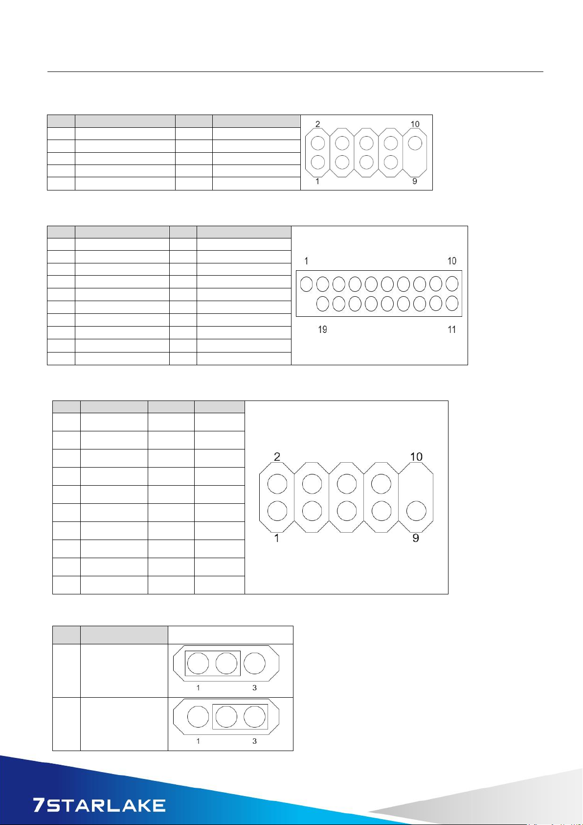
Front Panel Header
PIN
DEFINITION
PIN
DEFINITION
1
HDD_POWER_LED
2
POWER_LED_MAIN
3
HDD_LED#
4
POWER_LED_ALT
5
GND
6
POWER_SWITCH#
7
RESET_SWITCH#
8
GND
9
+5V_DC
10
Key(no pin)
ATX Power Input Header
PIN
DEFINITION
PIN
DEFINITION
1
GND
2
DC12V_IN
3
GND
4
DC12V_IN
TPM Header
PIN
DEFINITION
PIN
DEFINITION
1
SPI_CLK
7
3VSB
2
PLTRST_N
8
TPM_DET
3
SPI_MOSI
9
TPM_PIRQ_N
4
SPI_MISO
10
VCC3_TPM
5
SPI_CS2_N
11
GND
6
NC
CPU/SYS FAN Header
PIN
DEFINITION
1
GND
2
+12V
3
CPU_FAN_TACH
4
CPU_FAN_CTRL
Serial Port Pin-Out(COM1/COM2)
PIN
DEFINITION
PIN
DEFINITION
1
DCD
2
RXD#
3
TXD#
4
DTR
5
GND
6
DSR
7
RTS
8
CTS
9
RI
10
Key(no pin)

INS8367A User’s Manual V1.1
Revision Date: Sep. 01. 2023
12
Debug : P2398 Card Header
PIN
DEFINITION
PIN
DEFINITION
1
GND
2
VCC (5V)
3
Power Button
4
KEY
5
PORT80_A
6
3VSB
7
PORT80_B
8
PORT80_E
9
PORT80_C
10
PORT80_F
11
PORT80_D
12
PORT80_G
13
PORT80_DGH
14
PORT80_DGL
15
Dip switch_GPIO42
16
Dip switch_GPIO43
AT/ATX Mode Jumper
SATA Power Header
PIN
DEFINITION
1
12V
2
GND
3
GND
4
VCC(5V)
INTRUDER Header
PIN
DEFINITION
1
INTRUDER_N
2
Key(no pin)
3
GND
PIN
DEFINITION
1-2
AT Mode
2-3
ATX Mode(Default)
INS8367A User’s Manual V1.1
Revision Date: Sep. 01. 2023
13
Dual USB2.0 Header
PIN
DEFINITION
PIN
DEFINITION
1
5V_USB2_FP
2
5V_USB2_FP
3
USB2_HR1_1N
4
USB2_HR1_2N
5
USB2_HR1_1P
6
USB2_HR1_2P
7
GND
8
GND
9
Key (no pin)
10
No Connect
Dual USB3.0 Header
PIN
DEFINITION
PIN
DEFINITION
1
5V_USB3_FP
20
Key(no pin)
2
USB3P4_RXN-
19
5V_USB3_FP
3
USB3P4_RXP
18
USB3P3_RXP
4
GND
17
USB3P3_RXP
5
USB3P4_TXN_C-
16
GND
6
USB3P4_TXP_C
15
USB3P3_TXN_C
7
GND
14
USB3P3_TXP_C
8
USB_PCH_C_DN5
13
GND
9
USB_PCH_C_DP5
12
USB_PCH_C_DN6
10
NC
11
USB_PCH_C_DP6
Serial Port Pin-Out(COM2)
PIN
RS232
RS422
RS485
1
DCD
NC
NC
2
RXD#
NC
NC
3
TXD#
NC
NC
4
DTR
NC
NC
5
GND
NC
NC
6
DSR
NC
NC
7
RTS
NC
NC
8
CTS
NC
NC
9
RI
NC
NC
10
Key(no pin)
NC
NC
Clear CMOS Header
PIN
DEFINITION
1-2
Normal(Default)
2-3
Clear CMOS

INS8367A User’s Manual V1.1
Revision Date: Sep. 01. 2023
14
PEX8_16: PEX8 or PCIEX16 Select Header
PIN
DEFINITION
1
Pull High
2
DFG[5]: PCI Express Bifurcation
High: 1 x16 PCI Express*
(Default)
Low: 2 x8 PCI Express
3
Pull Low
PIN
DEFINITION
1-2
Pins 1&2 closed: High: 1 x16 PCI Express*
(Default)
2-3
Pins 2&3 closed: Low: 2 x8 PCI Express

INS8367A User’s Manual V1.1
Revision Date: Sep. 01. 2023
15
Chapter 3: AMI BIOS UTILITY
This chapter provides users with detailed descriptions on how to set up a basic system
configuration through the AMI BIOS setup utility.
3.1 Staring
To enter the setup screens, perform the following steps:
• Turn on the computer and press the <Del> key immediately.
• After the <Del> key is pressed, the main BIOS setup menu displays. Other setup screens
can be accessed from the main BIOS setup menu, such as the Chipset and Power menus.
3.2 Navigation Keys
The BIOS setup/utility uses a key-based navigation system called hot keys. Most of the
BIOS setup utility hot keys can be used at any time during the setup navigation process.
Some of the hot keys are <F1>, <F10>, <Enter>, <ESC>, and <Arrow> keys.
Left/Right
The Left and Right <Arrow> keys moves the cursor to select a
menu.
Up/Down
The Up and Down <Arrow> keys moves the cursor to select a
setup screen or sub-screen.
+− Plus/Minus
The Plus and Minus <Arrow> keys changes the field value of a
particular setup setting.
Tab
The <Tab> key selects the setup fields.
F1
The <F1> key displays the General Help screen.
F10
The <F10> key saves any changes made and exits the BIOS setup
utility.
Esc
The <Esc> key discards any changes made and exits the BIOS
setup utility.
Enter
The <Enter> key displays a sub-screen or changes a selected or
highlighted option in each menu.

INS8367A User’s Manual V1.1
Revision Date: Sep. 01. 2023
16
3.3 Main Page
Field Name
BIOS Vender
Default Value
American Megatrends
Comment
This field is not selectable. There is no help text associated with it.
Field Name
Core Version
Default Value
5.24
Comment
This field is not selectable. There is no help text associated with it
Field Name
Compliancy
Default Value
UEFI 2.8 ; PI 1.6
Comment
This field is not selectable. There is no help text associated with it

INS8367A User’s Manual V1.1
Revision Date: Sep. 01. 2023
17
Field Name
BIOS Version
Default Value
Display the version of the BIOS
Comment
This field is not selectable. There is no help text associated with it
Field Name
Build Date
Default Value
Display build date of the BIOS
Comment
This field is not selectable. There is no help text associated with it.
Field Name
ME FW Version
Default Value
ME Firmware Version.
Comment
This field is not selectable. There is no help text associated with it.
Field Name
Processor Information
Default Value
Display the installed CPU brand.
Comment
This field is not selectable. There is no help text associated with it.
Field Name
Microcode Version
Default Value
Display the CPU microcode revision.
Comment
This field is not selectable. There is no help text associated with it.
Field Name
Total Memory
Default Value
Display the installed memory size.
Comment
This field is not selectable. There is no help text associated with it.
Field Name
Memory Slot 1
Default Value
Display the installed memory size of slot 1.
Comment
This field is not selectable. There is no help text associated with it
Field Name
Memory Slot 2
Default Value
Display the installed memory size of slot 2.
Comment
This field is not selectable. There is no help text associated with it
Field Name
Memory Frequency
Default Value
Display the installed memory Frequency
Comment
This field is not selectable. There is no help text associated with it.

INS8367A User’s Manual V1.1
Revision Date: Sep. 01. 2023
18
Field Name
Serial ATA Port 4
Value
Display the installed SATA device model/size of port 4.
Comment
This field is not selectable. There is no help text associated with it.
Field Name
Serial ATA Port 5
Value
Display the installed SATA device model/size of port 5.
Comment
This field is not selectable. There is no help text associated with it.
Field Name
Serial ATA Port 6
Value
Display the installed SATA device model/size of port 6.
Comment
This field is not selectable. There is no help text associated with it.
Field Name
Serial ATA Port 7
Value
Display the installed SATA device model/size of port 7.
Comment
This field is not selectable. There is no help text associated with it.
Field Name
System Date
Default Value
[Www mm/dd/yyyy]
Possible
Value
Www : Mon/Tue/Wed/Thu/Fri/Sat/Sun
mm : 1-12
dd : 1-31
yyyy : 1900-9999
Help
Set the Date. Use Tab to switch between Date elements. Default
Rangers: Year : 1900-9999
Months : 1-12
Days : Dependent on month Range of Years may vary.
Field Name
System Time
Default Value
[hh :mm :ss]
Possible
Value
hh : 0-23
mm : 0-59
ss : 0-59
Help
Set the Time. Use Tab to switch between Time elements.

INS8367A User’s Manual V1.1
Revision Date: Sep. 01. 2023
19
3.4 Advance Page
Field Name
Onboard Device
Help
Onboard Device Configuration
Comment
Press Enter when selected to go into the associated Sub-Menu.
Field Name
CPU Configuration
Help
CPU Configuration Parameters
Comment
Press Enter when selected to go into the associated Sub-Menu.
Field Name
VMD setup menu
Help
VMD setup menu
Comment
Press Enter when selected to go into the associated Sub-Menu.
Table of contents
Other Star Lake Motherboard manuals


