Star Lake INS8335A User manual
INS8335A
Mini ITX Industrial Motherboard
User’s Manual

SafetyInformation
Electricalsafety
Topreventelectricalshockhazard,disconnectthepowercablefromthe
electricaloutletbeforerelocatingthesystem.
Whenaddingorremovingdevicestoorfromthesystem,ensurethatthepower
cablesforthedevicesareunpluggedbeforethesignalcablesareconnected.If
possible,disconnectallpowercablesfromtheexistingsystembeforeyouadda
device.
Beforeconnectingorremovingsignalcablesfromthemotherboard,ensurethat
allpowercablesareunplugged.
Seekprofessionalassistancebeforeusinganadapterorextensioncord.These
devicescouldinterruptthegroundingcircuit.
Makesurethatyourpowersupplyissettothecorrectvoltageinyourarea.
Ifyouarenotsureaboutthevoltageoftheelectricaloutletyouareusing,
contactyourlocalpowercompany.
Ifthepowersupplyisbroken,donottrytofixitbyyourself.Contactaqualified
servicetechnicianoryourlocaldistributor.
Operationsafety
Beforeinstallingthemotherboardandaddingdevicesonit,carefullyreadallthe
manualsthatcamewiththepackage.
Beforeusingtheproduct,makesureallcablesarecorrectlyconnectedandthe
powercablesarenotdamaged.Ifyoudetectanydamage,contactyourdealer
immediately.
Toavoidshortcircuits,keeppaperclips,screws,andstaplesawayfrom
connectors,slots,socketsandcircuitry.
Avoiddust,humidity,andtemperatureextremes.Donotplacetheproductinany
areawhereitmaybecomewet.
Placetheproductonastablesurface.
Ifyouencounteranytechnicalproblemswiththeproduct,contactyourlocal
distributor
Statement
Allrightsreserved.Nopartofthispublicationmaybereproducedinanyformor
byanymeans,withoutpriorwrittenpermissionfromthepublisher.
Alltrademarksarethepropertiesoftherespectiveowners.
Allproductspecificationsaresubjecttochangewithoutpriornotice
1
RevisionHistory
RevisionDate
(dd.mm.yyyy)
Changes
Version1.010.07.2012Initialrelease
Version1.128.09.2012JP3jumpersetting
Version1.205.12.2012JP4jumperdefaultsetting
Packinglist
□INS8335AMini‐ITXIndustrialMB
□I/OShield
□1xSATACable
□2xCOMportscablew/bracket
□1xUSBcable
□CD(driver+user’smanual)
Ifanyoftheaboveitemsisdamagedormissing,pleasecontactyourlocal
distributor.
2

TableofContents
SafetyInformation........................................................................................................1
Electricalsafety....................................................................................................................1
Operationsafety..................................................................................................................1
Statement............................................................................................................................1
RevisionHistory............................................................................................................2
Packinglist....................................................................................................................2
Chapter1:ProductInformation....................................................................................5
1.1BlockDiagram................................................................................................................5
1.2KeyFeatures..................................................................................................................6
1.3BoardPlacement............................................................................................................8
1.4MechanicalDrawings.....................................................................................................9
Chapter2:JumpersandConnectors............................................................................10
Chapter3:AMIBIOSUTILITY.......................................................................................22
3.1Starting........................................................................................................................22
3.2NavigationKeys............................................................................................................22
3.3MainMenu..................................................................................................................23
3.4AdvancedMenu...........................................................................................................24
3.4.1ACPISettings..............................................................................................................................25
3.4.2CPUConfiguration......................................................................................................................26
3.4.3SATAConfiguration.....................................................................................................................28
3.4.4ThermalConfiguration...............................................................................................................29
3.4.4.1Platformthermalconfiguration..........................................................................................29
3.4.5IntelRapidStartTechnology......................................................................................................30
3.4.6IntelTXT(LT)Configuration.........................................................................................................31
3.4.7PCH‐FWConfiguration...............................................................................................................31
3.4.8IntelAnti‐TheftTechnologyConfiguration.................................................................................32
3.4.9AMTConfiguration.....................................................................................................................33
3.4.10USBConfiguration....................................................................................................................34
3.4.11F81866SuperIOConfiguration................................................................................................35
3.4.12F81866H/WMonitor...............................................................................................................36
3.4.13SerialPortConsoleRedirection................................................................................................37
3.4.14CPUPPMConfiguration...........................................................................................................38
3.5Chipset.........................................................................................................................39
3.5.1PCH‐IOConfiguration.................................................................................................................39
3.5.1.1USBConfiguration..............................................................................................................41
3.5.1.2PCHAzaliaConfiguration....................................................................................................42
3.5.2SystemAgent(SA)Configuration...............................................................................................43
3.5.2.1GraphicsConfiguration.......................................................................................................44
3.5.2.2MemoryConfiguration.......................................................................................................45
3.6BootSetting.................................................................................................................46
3.7Security........................................................................................................................47
3

3.8Saveandexit................................................................................................................48
4

Chapter1:ProductInformation
1.1BlockDiagram
5
1.2KeyFeatures
Processor&System
CPUTypeIntel®22nmIvyBridgeProcessor(Mobile)socket
(rPGA988)
ChipsetIntel®QM77
MemoryType2x204‐pinSO‐DIMMsupportupto8GBdualchannel
DDR31333/1600,Non‐ECC
BIOS AMI®UEFIBIOS
SupoerI/OF81866D‐I
Watchdog1‐255sec.or1‐255min.softwareprogrammable,can
generatesystemreset
ExpansionSlot1xPCIex1
1xMiniPCIe
1xPCI
Display
ChipsetIntegratedGFXinIvyBridgeprocessor
OnboardVGAYes,Max:SXGA2048x1536@60Hz
LVDSDualchannel24‐bitLVDS,Max.1920x1200
OnboardDVI‐DYes,(Max.resolution1920x1200)
OnboardHDMIYes,(Max.resolution1920x1200)
IndependentDisplay
Capability
VGA,LVDS,DVI,HDMI
Audio
CodecRealtekALC892HighDefinitionAudioCodec
Ethernet
ChipsetIntel®82579LM&82574ITGbE
WOLYes
BootfromLANYesforPXE
RearI/O
VGA1
DVI‐D1
HDMI1
Ethernet2xRJ45
USB4xUSB3.0
AudioMic‐in,Line‐in,Line‐out
COMPort1xRS232/422/485with5V/12Vselectable
DCJack1
InternalI/O
SATA2xSATAIII(6Gb/s)
2xSATAII(3Gb/s)
CF‐SATA1
LVDS30‐pinconnector
USB8xUSB
4xUSB3.0portsonrearI/O
4xUSB2.0portsbypinheader
6

COM 6xCOMports
COM1portRS232/422/485with5V/12Vselectableon
rearI/O
COM2~3portsRS232with5V/12Vselectablebypin
header
COM4portsupportsRS232bypinheader
COM5~6portsRS232/422/485bypinheader
DIO16‐bit(4in/4out)
PS/21xpin‐headerforPS/2keyboardandmouse
Fan1xCPUfan,1xSystemfan
ParallelPort2x13‐pinheader
MechanicalandEnvironment
FormFactorMini‐ITX
PowerType9Vto24VDC‐in
Dimension170x170mm(6.7"x6.7")
OperatingTemp.‐20to70°C
RelativeHumidity10%to90%,non‐condensing
*Allspecificationsandphotosaresubjecttochangewithoutnotice.
7

1.3BoardPlacement
8

1.4MechanicalDrawings
9
Chapter2:JumpersandConnectors
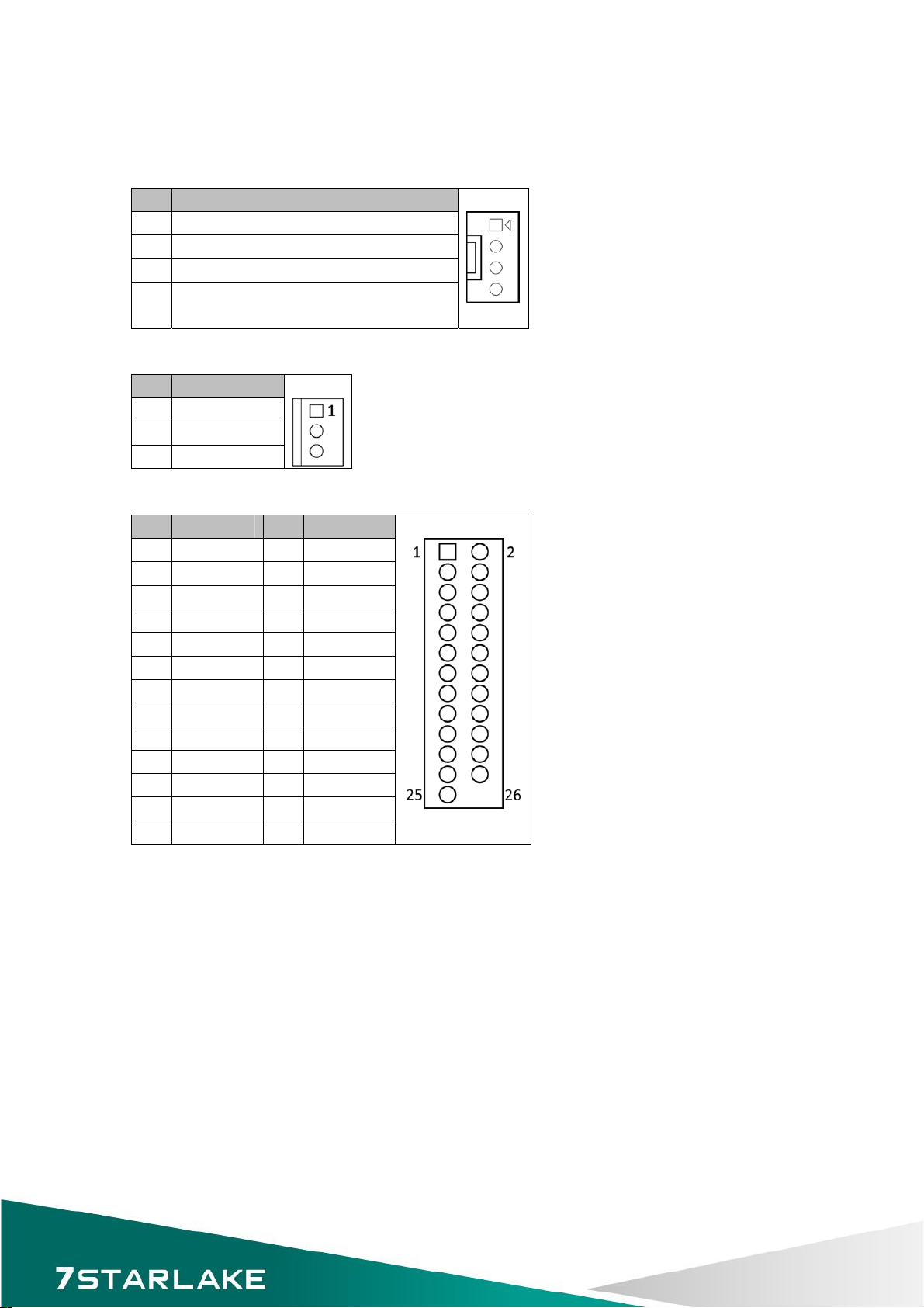
CPUFAN:4pinFANconnector
PinDefinition
1GND
2CPUFAN_VCC
3CPUFAN_TAC
4NC
(Optionfor4pinPWMFANcontrol)
SYSFAN:3pinFANconnector
PinDefinition
1GND
2SYSFAN_VCC
3SYSFAN_TAC
LPT1:LPTportpinheader
PinDefinitionPinDefinition
1STB#2AFD#
3SPD04ERROR#
5SPD16PINIT#
7SPD28SLIN#
9SPD310GND
11SPD412GND
13SPD514GND
15SPD616GND
17SPD718GND
19ACK#20GND
21BUSY22GND
23PE24GND
25SLCT26
10

LVDS:LVDSconnector
PinDefinitionPinDefinition
1LVDS_BCLK2GND
3LVDS_BCLK#4LVDS_A3
5GND6LVDS_A3#
7LVDS_B38GND
9LVDS_B3#10LVDS_ACLK
11LVDS_B212LVDS_ACLK#
13LVDS_B2#14GND
15LVDS_B116LVDS_A2
17LVDS_B1#18LVDS_A2#
19LVDS_B020LVDS_A1
21LVDS_B0#22LVDS_A1#
23GND24LVDS_A0
25DDCCLOCK26LVDS_A0#
27DDCDATA28GND
29LVDS_VDD
(DefinebyJP4)
30LVDS_VDD
(DefinebyJP4)
JP4:LVDS_VDDpowerselect
JumperFunctiondescriptionSetting
1‐2+5V
3‐4+3.3V
5‐6+12V
*Defaultsettingis3‐4*
11

JBKL1:Inverterconnector
PinDefinition
1Backlightpower(+12V)
2Backlightpower(+12V)
3Backlightpower(+12V)
4+5V
5+5V
6GND
7GND
8Backlightenable
(VoltagelevelSelectbyJP3)
9Backlightbrightnesscontrol
(VoltagelevelSelectbyJP3)
10GND
JP3:Backlightcontrolvoltagelevelselect
JumperFunctiondescriptionSetting
5‐35V
1‐33.3V
*Defaultsettingis1‐3*
JP3:BacklightADJmodeselect
JumperFunctiondescriptionSetting
2‐4PWMmode
6‐4Voltagemode
*Defaultsettingis2‐4*
KBMS1:PS2KeyBoard/Mouse
PinDefinitionPinDefinition
1+5VAUX2GND
3 4GND
5MSDATA6KBDATA
7MSCLOCK8KBCLOCK
12

FP1:FrontPanel1
PinDefinitionPinDefinition
1HDLED+2PLED+
3HDD_ACT‐ 4PLED‐
5GND6PWRBTN‐
7SYSRST‐ 8GND
9NC
F_USB1:USB2.0port0,1pinheader
F_USB2:USB2.0port2,3pinheader
PinDefinitionPinDefinition
1+5VDUAL2+5VDUAL
3D‐ 4D‐
5D+6D+
7GND8GND
9 10GND
LAN1_USB12:USB3.0port0,1andLANconnector1
LAN2_USB34:USB3.0port3,4andLANconnector2
UpperUSBLowerUSBLAN
PinDefinitionPinDefinitionPin Definition
1+5VDUAL1+5VDUAL1D0+
2D‐ 2D‐ 2D0‐
3D+3D+3D1+
4GND4GND4D1‐
5StdA_SSTX‐ 5StdA_SSTX‐ 5D2+
6StdA_SSTX+6StdA_SSTX+ 6D2‐
7GND_DRIAN 7GND_DRIAN 7D3+
8StdA_SSRX‐ 8StdA_SSRX‐ 8D3‐
9StdA_SSRX‐ 9StdA_SSRX‐
DIO1:Digitalinput/outputpinheader
PinDefinitionPinDefinition
1SBDO02SBDI0
3SBDO14SBDI1
5SBDO26SBDI2
7SBDO38SBDI3
9+5V10GND
DIO2:Digitalinput/outputpinheader
PinDefinitionPinDefinition
1SBDO42SBDI4
3SBDO54SBDI5
5SBDO66SBDI6
7SBDO78SBDI7
9+5V10GND
13
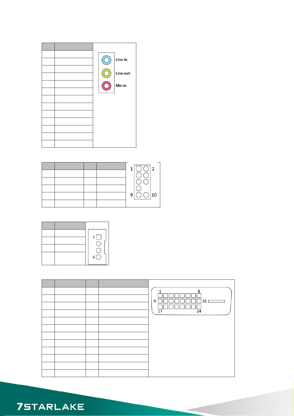
AUDIO1:LINE‐OUT/LINE‐IN/MIC‐IN
PinDefinition
A1LINE‐IN_L
A2LINE‐IN_JD
A3AGND
A4LINE‐IN_R
B1LINE‐OUT_L
B2LINE‐OUT_JD
B3AGND
B4LINE‐OUT_R
C1MIC_L
C2MIC_JD
C3AGND
C4MIC_R
C0AGND
AFP1:LINE‐OUT/MIC‐IN
PinDefinitionPinDefinition
1MIC2_L2AGND
3MIC2_R4A_GPIO
5LIN2_R6SRTN1
7SENSE_B8
9LIN2_L10SRTN2
AMP1:4ohm3WattAmplifieroutputpinheader
PinDefinition
1SP_OUTL‐
2SP_OUTL+
3SP_OUTR+
4SP_OUTR‐
DVI‐D:DVI‐D
PinDefinitionPinDefinition
1TMDS2‐ 13NC
2TMDS2+14+5V
3GND15GND
4NC16HOTPLUG_DETECT
5NC17TMDS0‐
6DDC_CLK18TMDS0+
7DDC_DATA19GND
8NC20NC
9TMDS1‐ 21NC
10TMDS1+22GND
11GND23TMDSCLK+
12NC24TMDSCLK‐
14

VGA:VGA
PinDefinitionPinDefinition
1RED9+5V
2GREEN10GND
3BLUE11NC
4NC12DDCDATA
5GND13HSYNC
6GND14VSYNC
7GND15DDCCLOCK
8GND
HDMI:HDMI
PinDefinitionPinDefinition
1HDMI_2P11GND
2GND12HDMI_CLKN
3HDMI_2N13NC
4HDMI_1P14NC
5GND15DDCCLOCK
6HDMI_1N16DDCDATA
7HDMI_0P17GND
8GND18+5V
9HDMI_0N19HOTPLUG_DETECT
10HDMI_CLKP
COM1:RS232/422/485with+12V/+5Vselection
PinRS‐232RS‐422HalfDuplexRS‐485
1DCD‐ TX‐ DATA‐
2RXDRX+NA
3TXDTX+DATA+
4DTR‐ RX‐ NA
5GNDGNDGND
6DSR‐ NANA
7RTS‐ NANA
8CTS‐ NANA
9COM1P9SEL
(DefinebyJP5)
COM1P9SEL
(DefinebyJP5)
COM1P9SEL
(DefinebyJP5)
COM2~COM3:RS232with+12V/+5Vselection
PinDefinitionPin Definition
1DCD‐ 2RXD
3TXD4DTR‐
5GND6DSR‐
7RTS‐ 8CTS‐
9COM2P9SEL/COM3P9SEL
(DefinebyJP6/7)
15
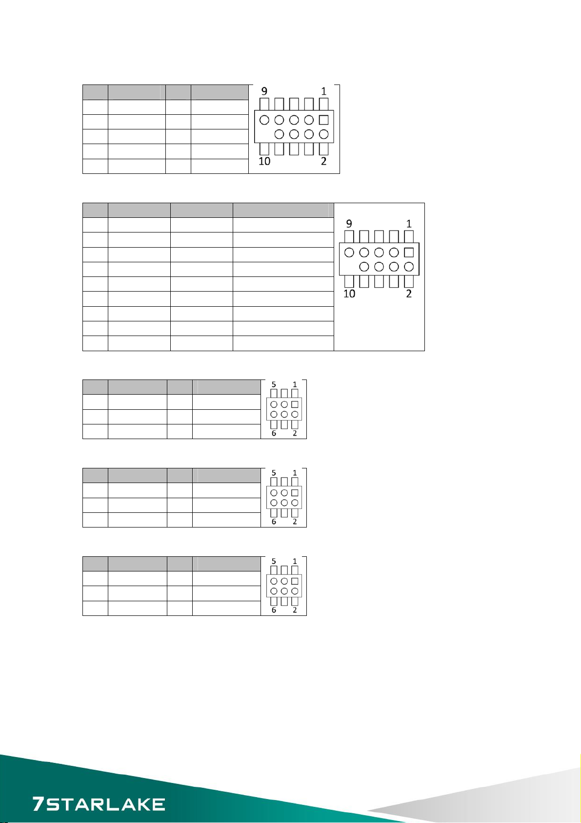
COM4:RS232
PinDefinitionPinDefinition
1DCD‐ 2RXD
3TXD4DTR‐
5GND6DSR‐
7RTS‐ 8CTS‐
9RI‐
COM5~COM6:RS232/422/485
PinRS‐232RS‐422HalfDuplexRS‐485
1DCD‐ TX‐ DATA‐
2RXDRX+NA
3TXDTX+DATA+
4DTR‐ RX‐ NA
5GNDGNDGND
6DSR‐ NANA
7RTS‐ NANA
8CTS‐ NANA
9RI‐ RI‐ RI‐
JP5:COM1+12V/+5Vselection
PinDefinitionPinDefinition
1COM1_RI‐ 2COM1P9SEL
3+5V4COM1P9SEL
5+12V6COM1P9SEL
JP6:COM2+12V/+5Vselection
PinDefinitionPinDefinition
1COM2_RI‐ 2COM2P9SEL
3+5V4COM2P9SEL
5+12V6COM2P9SEL
JP7:COM3+12V/+5Vselection
PinDefinitionPinDefinition
1COM3_RI‐ 2COM3P9SEL
3+5V4COM3P9SEL
5+12V6COM3P9SEL
16
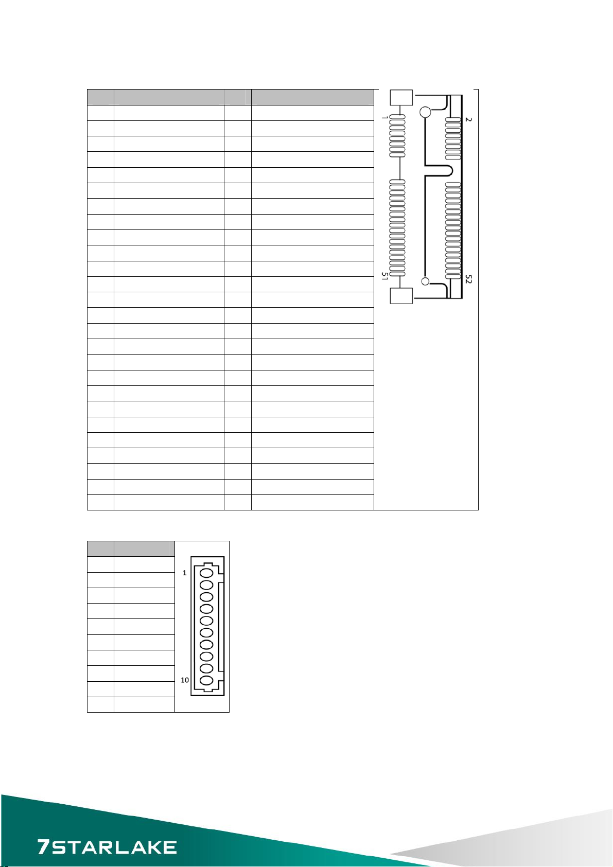
MINI_MPCIE:MiniPCIEconnector
PinDefinitionPinDefinition
1WAKE#2+3.3VAUX
3NC4GND
5NC6+1.5V
7CLKREQ#8NC
9GND10NC
11REFCLK‐ 12NC
13REFCLK+14NC
15GND16NC
17NC18GND
19NC20WirelessLANDisable#
21GND22RESET#
23RXN24+3.3VAUX
25RXP26GND
27GND28+1.5V
29GND30SMBUSCLOCK
31TXN32SMBUSDATA
33TXP34GND
35GND36USBDATA‐
37GND38USBDATA+
39+3.3VAUX40GND
41+3.3VAUX42NC
43GND44NC
45ControlLinkCLOCK46NC
47ControlLinkDATA48+1.5V
49ControlLinkRESET#50GND
51BlueToothDisable#52+3.3VVAUX
DEBUG:Debugcardconnector
PinDefinition
133Mhz
2RST#
3LFRAME#
4LAD3
5LAD2
6LAD1
7LAD0
8+3.3V
9GND
10GND
17

SATA1,SATA2:SerialATA3.0Connector
PinDefinition
1GND
2TXP
3TXN
4GND
5RXN
6RXP
7GND
SATA3,SATA4:SerialATA2.0Connector
PinDefinition
1GND
2TXP
3TXN
4GND
5RXN
6RXP
7GND
SATAP0,SATAP1:SATAPowerConnector
PinDefinition
1+5V
2GND
3GND
4+12V
JCMOS1:RTCReset
JumperFunctiondescriptionSetting
1‐2NormalOperation
2‐3ClearCMOS
*Defaultsettingis1‐2*
18

PSON1:ATX/ATmode
JumperFunctiondescriptionSetting
1‐2ATMode
2‐3ATXMode
*Defaultsettingis2‐3*
JCASE1:CaseOpenWarning
PinDefinition
1CASEOPEN#
2GND
PCIEX1_1:PCIExpressX1
PinSideBConnectorSideAConnector
1+12VNC
2+12V+12V
3+12V+12V
4GND GND
5SMBUSCLOCKNC
6SMBUSDATANC
7GNDNC
8+3.3VNC
9NC+3.3V
10+3.3VAUX+3.3V
11WAKE#PCIERESET
MechanicalKey
12NCGND
13GNDPCIECLOCK+
14PCIETXPPCIECLOCK‐
15PCIETXNGND
16GNDPCIERXP
17NCPCIERXN
18GNDGND
19
Table of contents
Other Star Lake Motherboard manuals


