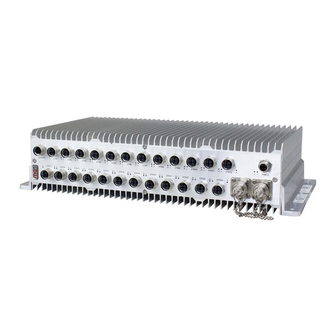
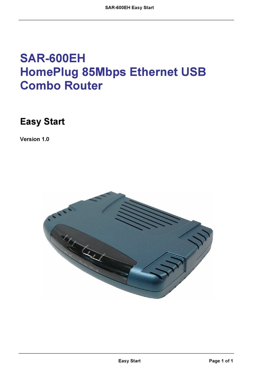
Star Microwave SM Cirius AO User manual

SM Cirius AO
Point-to-pointmicrowave IP radio with POE
Installation Manual

0.1 TABLE OF CONTENTS
Section
Page
0.1 TABLE OF CONTENTS ............................................................................................................2
0.2 OVERVIEW .............................................................................................................................4
0.3 DIMENSIONS AND WEIGHTS ..................................................................................................5
0.4 SAFETY PRECAUTIONS .......................................................................................................10
1 INSTALLATION TOOLS ..........................................................................................................12
1.1 INSTALLATION MATERIALS ...................................................................................................14
1.2 OPTIONAL CABLES & ANCILLARIES......................................................................................17
1.3 OPTIONAL EQUIPMENT.........................................................................................................19
2 BEFORE STARTING THE INSTALLATION ..............................................................................20
2.1 SITE PREREQUISITES...........................................................................................................20
2.2 CABLING OVERVIEW.............................................................................................................23
2.2.1 GBE ELECTRICAL CONNECTION FOR TRAFFIC& POWER....................................................23
2.2.2 FE ELECTRICAL CONNECTION FOR OUTBAND MANAGEMENT& POWER ...........................25
OVERVIEW.......................................................................................................................................25
2.2.3 GBE OPTICAL CONNECTION FOR TRAFFIC& FE CONNECTION FOR OUTBAND & POWER .28
3 CABLES PREPARATION........................................................................................................31
3.1 PREPARING POE GROUNDING CABLE .................................................................................31
3.2 PREPARING SM CIRIUS AO GROUNDING CABLE .................................................................34
3.3 PREPARING S-FTP CABLE ....................................................................................................36
4 POE INSTALLATION ..............................................................................................................42
4.1 INSTALLING POE ONTO POLE...............................................................................................42
PREREQUISITES..................................................................................................................................42
4.2 INSTALLING POE ONTO WALL...............................................................................................47
5 CABLING INSTALLATION.......................................................................................................49
5.1 POE CABLING INSTALLATION...............................................................................................49
5.1.1 INSTALLING GBE ELECTRICAL FOR TRAFFIC & POWER .....................................................49
PREREQUISITES..................................................................................................................................49
5.2 INSTALLING FE FOR OUTBAND MANAGEMENT & POWER ..................................................52
5.3 SM CIRIUS AO CABLING INSTALLATION...............................................................................56
5.3.1 INSTALLING GBE ELECTRICAL FOR TRAFFIC& POWER......................................................56
5.3.2 INSTALLING FE FOR OUTBAND MANAGEMENT& POWER ...................................................62
5.3.3 INSTALLING GBE OPTICAL FOR TRAFFIC& FE FOR OUTBAND & POWER...........................65
6 SM CIRIUS AO INSTALLATION ..............................................................................................75
6.1 INSTALLING ANTENNA .........................................................................................................75
INSTALL THEANTENNAACCORDING TO THEANTENNA MANUFACTURER’S INSTRUCTIONS...................................75
6.2 INSTALLING SM CIRIUS AO ONTO ANTENNA .......................................................................75
TOOLS 75
7 APPENDIXA –RECEPTACLES PIN OUT ...............................................................................78
7.1 SM CIRIUS AO.......................................................................................................................78

7.2 APPENDIX B: RMA (RETURN MATERIAL AUTHORIZATION) FORM ........................................83

0.2 OVERVIEW
Product Overview
SM Cirius AO is a cost-effective all-outdoor IP transmissionsolution.
It operates in 7, 8, 11, 13, 15, 18, 23, 26, 38 GHz frequency bands and modulations from 4QAM
to 256 QAM.
SM Cirius AO is provided together with the PoE (Power on Ethernet) box. PoE serves power and
traffic feeding from the Local Traffic Equipment towards SM Cirius AO.
SM Cirius AO
PoE

0.3 DIMENSIONS AND WEIGHTS
The following table shows the dimension &weight for the relevant products:
#
SM CIRIUS AO
POE
POE Pole (1)
Mounting Kit
Dimensions
(H x W x D),
mm
138 x 326 x 285
170 x 150 x 39
270 x 150 x 52
Weight, kg:
< 7.0 (7, 8 GHz)
< 6.5 (11, 13, 15, 18,
23, 26
& 38 GHz)
0.5
1.0
SM CiriusAO (Horizontalview)
No.
Description
1
Cable Holder screws (forfastening Ethernet & Opticalcables).
2
Grounding.
3
BNC receptacle (for measuring RSSIvalue).
4
Padlock hasp (x 2)
5
Clamps(x4 - for mounting SM CIRIUS AO onto antenna).
NOTE: SM Cirius AO receptacles are protected with a metallic cap, as shown above.

SM CiriusAO (Vertical view)

No.
Description
1
Handle
2
Waveguide port (with antenna polarizer)
SM CiriusAO (Interfacesview)
No.
Description
1
RJ-45 (GbE electrical 100/1000 Mbps) receptaclefor SM Cirius AO interconnection
(1+1 or 2+0).
2
RJ-45 (FE 10/100 Mbps) receptacle for outband management & power(1).
3
RJ-45 (GbE electrical 100/1000 Mbps) receptaclefor traffic, inband management &
power(1).
4
SFP (GbE optical or electrical1000 Mbps) receptacle for traffic & inband management.

POE (Equipment view)
No.
Description
1
PoE ResetButton / Output power down
2
Status LED.
3
DC input power receptacle.
4
Cable(s) clamp.
5
Top cover screws (x6).
6
Wall mounts holes (x4).
7
Pole mounts points (x2).
8
Terminal ring for grounding (supplied with PoE device).
NOTE: PoE device canbe installed either indoor or outdoor.

POE (Interfacesview)
No.
Description
1
RJ-45 ((GbE (IN) electrical 100/1000 Mbps)) receptacle for traffic.
2
RJ-45 ((GbE(OUT) electrical100/1000 Mbps)) receptacle for traffic & power to SM
Cirius AO
3
RJ-45 ((NMS (IN) 10/100 Mbps)) receptacle for outband management.
4
RJ-45 ((NMS(OUT) 10/100Mbps)) receptacle for outband management & power to SM
Cirius AO
Transportationand storage conditions
The product is designed to be transported and stored under the following conditions:
Temperature: -40 C to +70 C according to ETSI EN 300 019-2-2 V2.1.2, Class 2.3
(transportation) &300 019-2-1 V2.1.2, Class 1.2 (storage)
Relative Humidity: 90% to 100% at +30 C (condensation) 93% at +30 C (steady state)
NOTE: The preceding values apply only when the product is in its package.
Operatingtemperature
The product is designed to operate at the following temperature range:
Temperature: -33 Cto +55 Caccording to ETSI EN300 019-2-4 V2.1.2, Class 4.1
(Operational at -50 C,Cold start at -50 C)

0.4 SAFETY PRECAUTIONS
WORKING ON T HE BUILDING’S ROOF
During stormy weather, do not perform any mechanical ass embling or
antenna beaming works on the building’s roof.
The metal structure of towers / masts is prone to lightning
PROPER GROUNDING
Never power up PoE box unless y ou have grounded both SM Cirius AO and
PoE as described in this manual.
There is risk of equipment failure and/or electrical shock.
Ensure that the grounding system meas ures an appropriate path resistance
as specified by local regulations.
Ensure that an appropriate grounding terminal exists at the proximity of
each equipment installation position.
PLUGGING / UNPLUGGING THE S-FTP CABLE(S) OF SM Cirius AO
Never plug in or unplug the S -FTP c able(s) of SM Cirius AO when PoE box
is powered on and operating unless you have grounded both SM Cirius AO
and PoE as described in this manual.
There is risk of equipment failure and / or electrical shock.

PoE PROPER CONNECTION
Never c onnect the Ethernet output receptacles of PoE box to network
switches / routers.
There is risk of network switc hes / routers failure due to potential carried
power.
Connect the Ethernet output receptacles to SM CIRIUS AO as described in
this
manual
PoE PROPER SWITCHING ON / OFF
Never connect or disc onnect the power cable to or from the PoE box when
the Local DC Power Supply Source is on.
There is risk of equipment failure.
Ensure the Local DC Power Supply Source is off and then connect or
disconnect the power cable to or from the PoE box.
LASER RADIATION
SM Cirius AO, when SFP is used, is a CLASS 1 laser product.
ESD PROTECTION
Always use proper antistatic protection (i.e. grounding bracelet, antistatic
bags, etc.) when handling the product cards.
Parts bearing the ESD sign (see left) have ESD sensitive
exposedcomponents

1 INSTALLATIONTOOLS
The following list of tools is required for equipment installation. This particular list of tools is not
supplied with the product and is installer responsibility to be provided during installation.
Item
Photo
Description
1
Cross-headed (Philips)
screwdriver (PH-2).
2
Flat-headed
screwdrivers
(AZ-10, AZ-5.5, AZ-2.5).
3
Torx Plus screwdriver
10IP.
4
Blade.
5
Set of Allen (hexagonal)
keys.
6
Cable cutter.
7
Set of U-type
wrenches(from 5 mm up
to
29 mm).

Item
Photo
Description
8
Crimping tool for 16
mm2 cable.
9
Crimping tool for 6 mm2
cable.
10
Crimping tool for S-FTP
cable with RJ-45 jack.
11
Hot air blower.
12
Ethernet cable tester.
12
Drilling machine (with
bits) is required only for:
Mounting PoE onto
wall (using 5 mmbit)
Mounting PoE onto
wall (using 8mm bit)

1.1 INSTALLATION MATERIALS
Overview
This sectiondescribes all the accessories /ancillaries / materials related to SM CIRIUS AO
installation. The quantity is per site and the configuration is 1+0.
Overview
SM CIRIUS AO
Description
Qty
Details
SM CIRIUS AO
1
Available in 7, 8, 11, 13, 15, 18, 23, 26, 38 GHz
frequency bands
PoE Package
Overview
PoE box includes the following:
PoE Device
PoE Pole Mounting Kit
M20 Cable Gland
Cable Holder

PoE device
Item
Description
Qty
Details
A
PoE
1
PoE with DC source
B
PoE wall mounting
installation materials
1
Set of 4 x Wood Plugs
(5mm X 25mm)
C
1
Set of 4 x Wood Screws
(4mm x 30mm)
PoE pole
mounting kit
Item
Description
Qty
Details
A
Mounting Bracket
1
Stainless Mounting Bracket for
attaching PoEonto pole
B
Hose Clamp
1
Metallic Band Hose Clamp, W=14mm &
L=1000mm for mounting bracket onto
pole.
C
Clamp Screw
2
Metallic Screws for Hose Clamp pole.

D
Lock Washer
4
M8 lock washers (DIN127B), stainless.
E
Screw
6
M8x10 cross-headedscrew,stainless.
F
Washer
4
M8 washers (DIN125A), stainless.
G
Tie-wrap
12
Tie-wraps for cable fastening onto
stainless mounting bracket
(3.5x200mm, UV protected).
M20 Cable Gland
Description
Qty
Details
M20 Cable Gland
1
SM CIRIUS AO Cable Gland M20 (with spacer)
for RJ-45 receptacles
Cable Holder
Description
Qty
Details
Cable Holder
1
Cable holder for fastening S-FTP &Optical fiber
cable(s).

1.2 OPTIONAL CABLES & ANCILLARIES
The following list of materials (Cables & Ancillaries) is optional
Item
Photo
Description
Qty
Details
A
PoE Powercable
Required
length
provided
SolidCored PowerCablefor
outdooruse:(2x 2.5 mm2,PVC,
1KV, Blue/Brown).
B
PoE Grounding
Cable
Required
length
provided
StrandedGroundingCable for
outdooruse:(6mm2,PVC,
450V, Yellow/Green).
C
Ethernet Cable
Required
length
provided
S-FTP Ethernet Cable for
indoor/outdooruse:
((Shielded,Black,Ultra Violet
(UV), Cat.5E, 4x2xAWG24)).
D
RJ45Connector
for Ethernet cabl
Required
pieces
provided
Connectorfor S-FTP cable
termination.
E
Fiber Optic Cable
1
Fiber Optical Cableoutdooruse:
DX,MM,2xLC/PC-LC/PC,
100
meters.
DX,MM,2xLC/PC-LC/PC,
150
meters.
DX,MM,2xLC/PC-LC/PC,
200
meters.
F
RSSI Cablefor
1
RSSI Cableassemblyfor SM
CIRIUS AO
antennaalignment:
(Male BNC to 2 x bananaplugs,
75Ω).
G
GreasingPaste
1
Greasing paste for antenna
Oring.
H
CableTie Wraps
1
Set of 50x tie-wraps forcable
fasteningoutdooruse(1).
(12.5x500mm,Black,UV
resistant)
I
M20 CableGland
Required
pieces
provided
SM CIRIUS AO CableGland
M20 (withspacer)for RJ-45
receptacles.
J
M25 CableGland
for Optical
FibrePort
1
SM CIRIUS AOCable Gland
M25 (withspacer& thread
extension))for Optical Fiber
receptacle.

K
Grounding Kit
for SM CIRIUS
AO
1
The kit consist of the
following:
(A): Grounding cable:
1 x 2 m cable, 16 mm2,
stranded, PVC, green /
yellow,
450 V
(B):1 x M8 Terminal ring
(C): 1 x M5 Terminal ring
(D): Set of:
2 x Screws, M8 x 25
2 x Nuts, M8
2 x Washers, M8
6 x Lockwashers, M8
1 x Tie-wrap
(E):1 x Heat shrinkable tube:
black, d = 9,5 mm / 4,8 mm
(F):1 x Terminal pin: AWG6,
Non insulated

1.3 OPTIONAL EQUIPMENT
The following list shows the available optional equipments:
Item
Photo
Description
Qty
Details
A
Optical SFP
1
Single & Multi mode of
various specs &
distances
B
Crimping Tool
Required
number
provided
For S-FTP Cable
Termination with RJ-45
Plug
C
DIN Rail Mount
Required
number
provided
230 VAC / 48 VDC

2 BEFORESTARTINGTHE INSTALLATION
2.1 SITE PREREQUISITES
Introduction
This section describes all the prerequisites that must be considered prior to installing the
equipment.
Site Survey
Site survey should be done before startthe installation taken in consideration the following:
Premises information
Site details (address,contactpersons, GPS and/or mapco-ordinates, etc.)
Site access and storage information (meansof transport, equipment storage and lifting
information, etc.)
Site location maps
Network planning
Geographical positions of the site
LOSbetween the sites
Rain zone
Polarization of the antennas
Height of all buildings at the installation premises
Rooftop information (height, status,access,dimensions,layout, etc.)
Information about pre-existing indoor/ outdoor equipment
Available mounting space (on the buildings’ roofs) to reserve for the installation of the
outdoor equipment
Site-specific information
Mechanical specifications of masts/ towers (type, dimensions/ diameter,material, exterior
finishing, etc.)
Location of appropriate grounding points (bar or terminals)
Location of appropriate power supply distribution points
Location of cable conduits available for routing the cables
Location of the network port distributors
Total length of the cables required
Table of contents
