Star Microwave SM Sygnus SHC User manual

SM SYGNUS SHC USER´S MANUAL
1
SM Sygnus SHC
MULTI-MIMO OFDM OUTDOOR RADIO
User’s Manual
Includes install, configuration and trouble
shooting information for the broadband
Wireless access outdoor radio

SM SYGNUS SHC USER´S MANUAL
2
The information contained in this document is of commercial value, and is proprietary to Star
Microwave. It is conveyed to the recipient solely for the purpose of evaluation. Reproduction of this
document, disclosure of its contents or any other use of the information herein is strictly forbidden
unless expressly authorized in writing by Star Microwave.
Notices
Radio Frequency Statement
Sygnus SHC has been tested and found to comply with part 15 of the FCC rules and EN 301489-1 rules.
These limits are designed to provide reasonable protection against harmful interference when the
equipment is operated in a residential environment notwithstanding use in commercial, business and
industrial environments. Operation is subject to the following two conditions:
(1) This device may not cause harmful interference, and
(2) This device must accept any interference received, including interference that may cause
Undesired Operation.
IMPORTANT! It is the responsibility of the installer to ensure that when using the outdoor antenna kits
in the United States (or where FCC rules apply), only those antennas certified with the product are
used. The use of any antenna other than those certified with the product is expressly forbidden in
accordance to FCC rules CFR47 part 15.204.
IMPORTANT! Outdoor units and antennas should be installed ONLY by experienced installation
professionals who are familiar with local building and safety codes and, wherever applicable, are
licensed by the appropriate government regulatory authorities. Failure to do so may void the product
warranty and may expose the end user or the service provider to legal and financial liabilities. Star
Microwave and its resellers or distributors of this equipment are not liable for injury, damage or
violation of regulations associated with the installation of outdoor units or antennas.
Warranty
Star Microwave warrants that this product shall be free from defects in workmanship and materials
for a period of one year from the date of original purchase. If the product should fail to operate
correctly in normal use during the warranty period, Star Microwave will replace or repair it free of
charge. No liability can be accepted for damage due to misuse or circumstances outside Star
Microwave’s control. Star Microwave will not be responsible for any loss, damage or injury arising
directly or indirectly from the use of this product. Star Microwave’s total liability under the terms of
this warranty shall in all circumstances be limited to the replacement value of this product. If any
difficulty is experienced in the installation or use of this product that you are unable to resolve, please
contact Star Microwave.

SM SYGNUS SHC USER´S MANUAL
3
Table of Contents
Introduction............................................................................................................................................. 5
Applications............................................................................................................................................. 5
Technical Overview ................................................................................................................................. 6
Element Management System .............................................................................................................. 10
Standard Protocols................................................................................................................................ 11
Installation............................................................................................................................................. 12
Packing List ............................................................................................................................................ 12
Additional Part List –Required for Installation ..................................................................................... 12
Installation Overview ............................................................................................................................ 13
Testing before outdoor installation ...................................................................................................... 13
Quick Configuration............................................................................................................................... 13
Link configuration.................................................................................................................................. 14
SU Installation window.......................................................................................................................... 15
Checking the Setup................................................................................................................................ 15
Typical outdoor installation scheme: .................................................................................................... 15
Installation process summary: .............................................................................................................. 16
Select the Best Location ........................................................................................................................ 17
Path of Clearest Propagation ................................................................................................................ 17
Physical Obstacles ................................................................................................................................. 17
Minimal Path Loss ................................................................................................................................. 17
Mounting............................................................................................................................................... 18
Antennas ............................................................................................................................................... 18
General .................................................................................................................................................. 18
Tx power................................................................................................................................................ 18
Alignment .............................................................................................................................................. 19
The Sygnus SHC can be aligned using the Built in RSSI buzzer.............................................................. 20
Sealing ................................................................................................................................................... 20
Cables .................................................................................................................................................... 21
Indoor Outlet Installation...................................................................................................................... 23
Grounding.............................................................................................................................................. 24
Consecutive AP Connection .................................................................................................................. 25

SM SYGNUS SHC USER´S MANUAL
4
Synchronization..................................................................................................................................... 25
General Configuration:.......................................................................................................................... 26
Ethernet Configuration:......................................................................................................................... 26
GPS Synchronization (MU only): ........................................................................................................... 27
RF Analyzer............................................................................................................................................ 27
Appendix A –Outdoor Cables Scheme.................................................................................................. 28
Appendix B –RF Channel Lists............................................................................................................... 29
Appendix C –Approved Antennas......................................................................................................... 30

SM SYGNUS SHC USER´S MANUAL
5
Introduction
Thank you for purchasing Sygnus SHC point-to-point solution. Sygnus SHC is a carrier grade, the best
of its class point-to-point and Point-to-multipoint broadband wireless bridge. Sygnus SHC is the next
generation of radio technology with field proven features of Sygnus SHC.
Sygnus SHC comprises of Reliability, High Capacity, Lowest Latency, RF Robustness, Rugged outdoor
design, Flexibility and Simplicity to install and maintain.
Applications
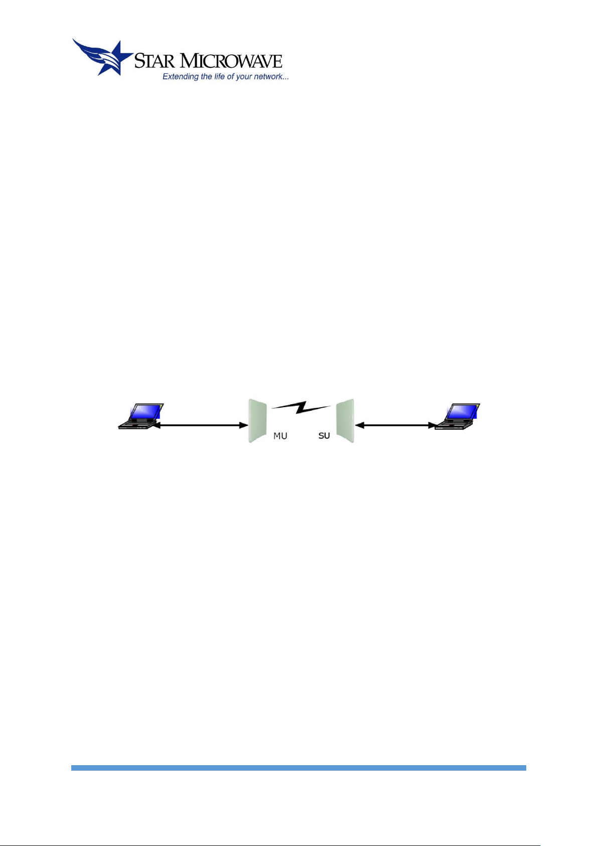
Point-to-Point (PTP):
The basic subsystem is composed of a Master Unit (MU) and a Slave Unit (SU).
Typical applications:
• IP data backhaul of:
• WiMAX operators
• Metro WiFi Networks
• Cellular and 3G
• Backhaul of video surveillance systems
Point-to-Multipoint (PTMP):
The basic subsystem is composed of the same Master Unit (MU) and multiple Slave Units (SUs).
Typical applications:
• Multiple backhauls solutions
• Multiple Video surveillance systems
• High bandwidth campus solutions

SM SYGNUS SHC USER´S MANUAL
6
Technical Overview
Sygnus SHC introduces unmatched benchmark of features and built in technological advantages:
• Advanced OFDM 2x2 MIMO - Utilizing superior Advanced OFDM 2x2 dual
polarization MIMO (Multiple Input Multiple Output), Sygnus SHC provides cutting
edge advantages:
• Higher capacity and spectral efficiency - 100 Mbps full duplex. 2x2 MIMO transmits 2 streams
that double the throughput on same channel bandwidth.
• Long range - MIMO can deliver same throughput by transmitting two (2) lower rate streams,
achieving sustained throughput over long distances.
• Increased reliability and availability - transmitting 2 lower rate streams provides higher fade
margin, increasing reliability and link’s availability.
• High capacity – up to 270 Mbps net throughput.
• Low latency - 1msec typical (PTP). Ideal for backhaul, multi-hop backhauls and voice, video &
interactive applications.
• More than 50,000 PPS (Packets Per Second) –ideal for VOIP backhaul applications
• Superior 7.5 bit/Hz spectral efficiency – 300 Mbps over 40 MHz channel via:
• 2x2 dual polarization MIMO
• Advanced OFDM:
• Higher number of OFDM Subcarriers.
• Reduced guard interval.
• Forward Error Correction of 5/6 @ 64QAM
• Symmetric / dynamic throughput - up/downstream throughput can be symmetric or dynamic &
application. Automatic according to the actual traffic, optimizing the link to the
• Output Power - High dynamic range of 40 dB up to 26 dBm.
SM SYGNUS SHC USER´S MANUAL
7
• Versatile radio – increase flexibility and scalability:
• Configurable channel bandwidth (5/10/20/40 MHz) maximizes capacity and availability.
• Multiple frequency bands in one radio.
• RF and interference robustness - Sygnus SHC introduces unique and robust
interference mitigation mechanisms:
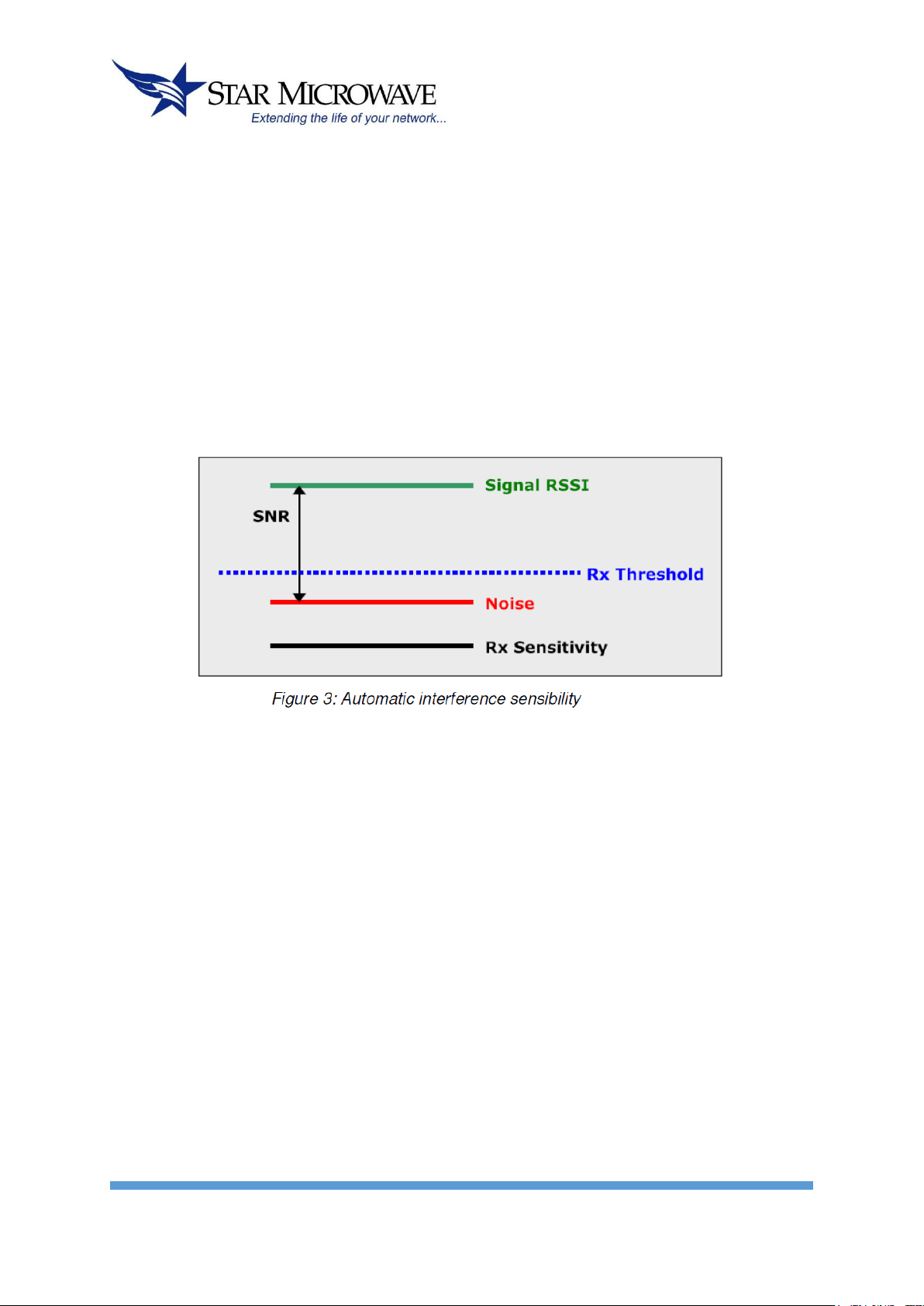
• Automatic Interference Sensibility - proprietary solution that increases RF robustness by
eliminating false receptions of noise thus maintaining constant throughput and latency. The
automatic sensibility sets an Rx threshold above the noise level as shown in figure 3.
• ACM - Adaptive Modulation and Coding (modulation can be defined manually as well).
• FEC - Forward Error Correction, K = 1/2, 2/3, 3/4, 5/6.
• Fast ARQ - Automatic Retransmit reQuest.
• 128-bit AES encryption –non-compromising security.
• Networking and QoS – built in QoS in both PTP and PTMP modes:
• Bandwidth control – define maximum throughput for each direction (uplink and downlink)
independently.
• 8 priority queues – packets are classified according to TOS and VLAN priority into the queues
(7 = highest priority and 0 = lowest priority).
• Packet filtering: VLAN based and broadcast filters.
• VLAN tagging/stripping per terminal.
• Real time synchronization - by GPS or internal. Sygnus SHC built in time
synchronization technology allows collocation of multiple MUs on the same tower
and on collocated towers while reusing frequencies, eliminating self-interference
between them.

SM SYGNUS SHC USER´S MANUAL
8
Without time synchronization, one MU will transmit while the other MU receives. The transmission of
the first MU will block the reception of the second MU since they are close to each other (can even
occur when the MUs are on different channels).
Time synchronization synchronizes the transmission and reception of all MUs, thus eliminating self-
interference between them and allowing better frequency reuse.

SM SYGNUS SHC USER´S MANUAL
9
• Built in redundancy -
• Power & data redundancy via 2xRJ-45.
• 1+1 Trunking capability.
• Consecutive AP™ - concatenation capability with power redundancy, as shown in figure 7.
• Lowest total cost of ownership - Engineered for affordability, Sygnus SHC empowers
operators with extremely low CAPEX & OPEX:
• Most competitive price
• Rugged & reliable weather proof design
• Compact and very simple to install:
• Fast installation by 1 technician.
• Built in RSSI buzzer for easy alignment.
• Built in RF analyzer - simplest site survey tool.
• ACS – Automatic Channel Selection (automatic site survey).
• Extremely low power consumption: < 6Watt.
• Multiple frequency bands in one radio – ease of stocking and maintenance.
• Over the air remote management
SM SYGNUS SHC USER´S MANUAL
10
Element Management System
Sygnus SHC is managed in three ways:
NMS
As part of a deployment, The Network Management System (NMS) provides one point of
management for all the links deployed and allows the operator to monitor and control the units:
• Managing entire deployment composed of Sygnus SHC Radios
• Radio link monitoring and configuration.
• Easy PTMP configuration – all in one point.
• System health in a glance.
• Multiple networking modes under single MU.
Figure 8: Network Management System
SM SYGNUS SHC USER´S MANUAL
11
Standard Protocols
Sygnus SHC supports the following protocols:
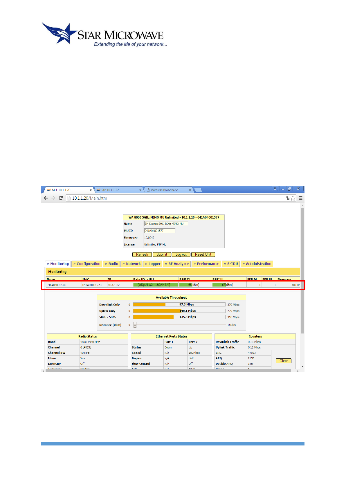
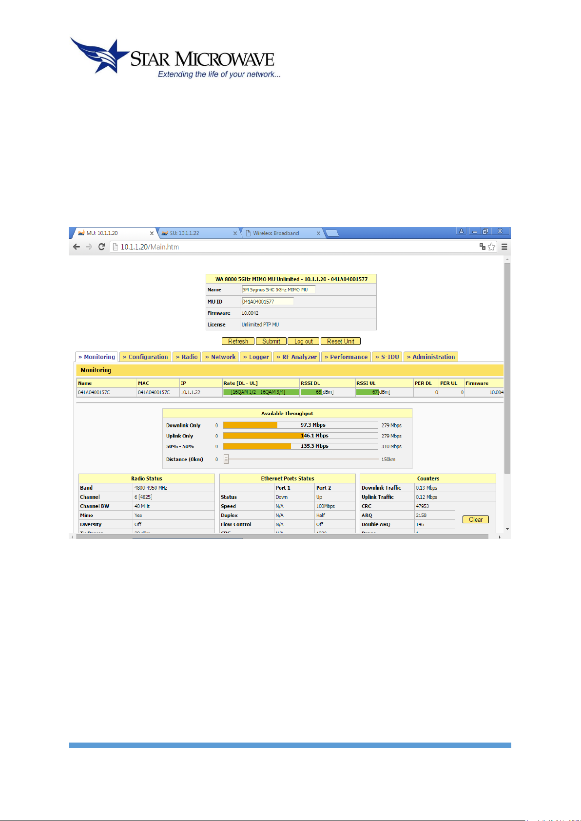
• WEB (HTTP) –Manage the radio using an Internet browser.
• SNMP – Supports v2c with a private MIB, Traps and notifications.
• Telnet.
Figure 11: WEB interface
SM SYGNUS SHC USER´S MANUAL
12
Installation
Packing List
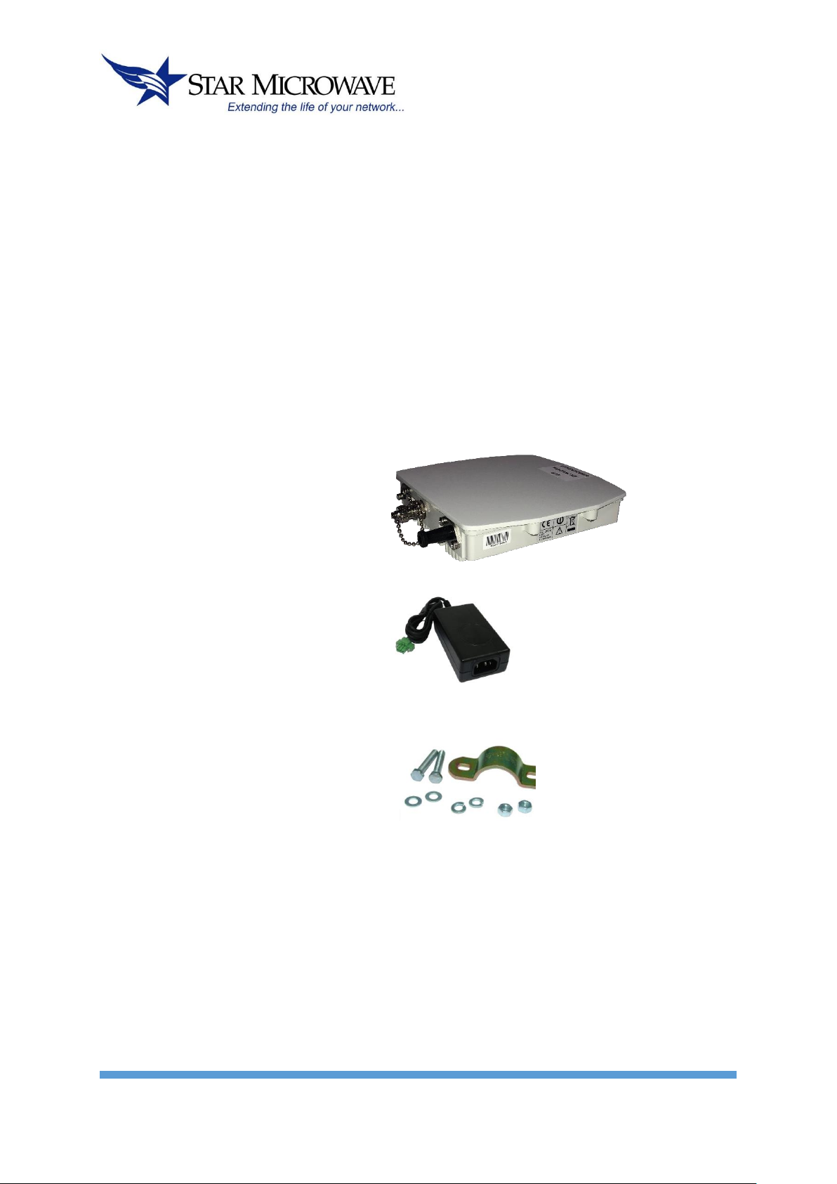
When you first open the package, verify that the unit is complete with the following components:
1. Outdoor Unit –Sygnus SHC MU or SU.
2. Indoor PoE Outlet.
3. Pole mounting kit (will not be added if advanced mounting kit is provided).
1.
2.
3.
Additional Part List –Required for Installation
• Outdoor Unit grounding cable
• Outdoor-to-Indoor shielded CAT5 cable (Up to 90 meters).
• Indoor CAT5 cable.
• RJ-45 - Installation KIT.
• RJ-45 - Crimping tool.
• Adjustable wrench + screwdriver.
SM SYGNUS SHC USER´S MANUAL
13
Installation Overview
This section provides installation information for Sygnus SHC System.
__________________________________________________________________________________
Note: Outdoor units and antennas should be installed ONLY by experienced installation professionals
who are familiar with local building and safety codes and, wherever applicable, are licensed by the
appropriate government regulatory authorities. Failure to do so may void the product warranty and
may expose the end user or the service provider to legal and financial liabilities. Star Microwave and
its resellers or distributors of this equipment are not liable for injury, damage or violation of regulations
associated with the installation of outdoor units or antennas.
Testing before outdoor installation
Star Microwave recommends setting the link up first in your facility and bench test before deployment.
Mount the antennas so they are separated with at least 20 feet of distance at the lowest power output
setting.
Quick Configuration
The Sygnus SHC link is supplied pre-configured so once the units are powered, you will have
connectivity between the 2 PCs.
The following sections will guide you through the basic configuration of the link.

SM SYGNUS SHC USER´S MANUAL
14
Link configuration
• MU ID: Configure the MU ID to be identical to the MU’s MAC address.
• Channel: select the desired channel to operate on.
• SU MAC Address: Configure the SU MAC address.
• DL Rate: Select the modulation for the downlink traffic (from the MU to the SU).
• UL Rate: Select the modulation for the uplink traffic (from the SU to the MU).
• Channel BW: Select the required channel bandwidth – 40/20/10/5 MHz The same
value should be configured in both MU and SU. Default –20 MHz
• Enable MIMO: For Sygnus SHC only – activate/deactivate 2x2 MIMO. The same
value should be configured in both MU and SU. Default –enabled in Sygnus SHC.
• Current Rate: Shows the current modulation for DL and UL.
• Pre-Shared Key: Configure the AES pre-shared key (used when AES is enabled). The
same shared key should be configured in both MU and SU.
• Enable AES: Check to enable AES encryption. Default – disabled.
• Enable AIS: Check to enable Automatic Interference Sensibility. Default – enabled.
• Enable ACS: Check to enable Automatic Channel selection after AU power cycle.
• Default – enabled.
• Perform ACS: Press this button to start Automatic Channel selection immediately.
• VLAN ID: management VLAN ID (default – 0, no VLAN ID).
• Sync Unit: After configuring all parameters, press “Sync Unit” to submit the
configuration to the MU.

SM SYGNUS SHC USER´S MANUAL
15
SU Installation window
• Go to the installation window and configure the SU’s desired management IP (for example:
10.40.40.253).
• Configure the primary MU ID (same MU ID that was configured at the MU’s link configuration
window).
• Configure the channels you want the SU to scan. You can leave all channels marked to scan the
entire band or select the exact channel configured at the MU.
• Press “Submit” to save the changes.
Checking the Setup
Make sure to provide some distance between the units to avoid transmission saturation. Align
the antennas in a way that keeps the RSSI level below –50 dBm
From the MU PC issue the command ping x.x.x.x –t, where x.x.x.x is the IP of the PC behind
the SU. Make sure both PCs are on the same subnet, for example: 10.1.1.10/24 and
10.1.1.20/24.
Typical outdoor installation scheme:
1. Sygnus SHC - Outdoor Unit with integrated Antenna
2. Outdoor to Indoor CAT5
3. Indoor Outlet
4. User computer
5. Indoor CAT5
6. Power
7. Supply
8. 100-240V
9. AC

SM SYGNUS SHC USER´S MANUAL
16
Installation process summary:
10. Select the appropriate location for the Outdoor unit and the indoor
PoE Outlet.
11. Mount the Outdoor unit. If you are using detached antenna mount
the antenna and connect it to the Outdoor unit.
12. Connect a ground cable between the Outdoor unit and an
appropriate grounding point.
13. Connect the Outdoor-to-Indoor shielded CAT5 cable to the Outdoor
unit and route it to the location selected for the PoE Outlet.
Assemble the enclosed connector on the cable.
14. Mount the Indoor Outlet.
15. Connect the Outdoor-to-Indoor cable to the PoE Outlet
‘OUTDOOR’ port. (This port supplies 48 VDC in addition to the
Ethernet data).
16. Connect the CAT5 Ethernet cable from the user’s network/PC to
the PoE Outlet ‘10/100 B-T’ port.
17. Connect the power supply to the PoE Outlet power port (‘48VDC’).
18. Align the antenna and secure the unit by fastening the mounting
screws.

SM SYGNUS SHC USER´S MANUAL
17
Select the Best Location
Select the appropriate locations for the outdoor unit using the following guidelines:
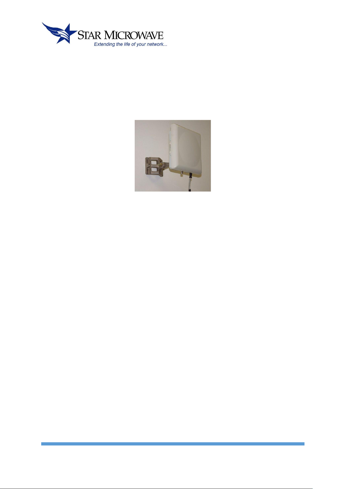
• The outdoor unit can be pole or wall mounted.
• The location should allow easy access to the unit for installation.
• When using an external antenna, the unit should be installed as near as possible to the antenna.
• Make sure clear Line of Sight between the units.
Path of Clearest Propagation
A propagation path is the path that signals traverse between the antennas of any two bridges. The
“line” between two antenna sites is an imaginary straight line, which may be drawn between the two
antennas. Any obstacles in the path of the “line” degrade the propagation path. The best propagation
path is, therefore, a clear line of sight with good clearance between the “line” and any physical
obstacle.
Physical Obstacles
Any physical object in the path between MU and SU can cause signal attenuation. Common
obstructions are buildings, trees and hills located in the path between the two sites. Install outdoor
antennas high enough to avoid any obstacles, which may block the signal.
Minimal Path Loss
Path loss is determined by several factors:
• Distance between sites – Path loss is lower when distances between sites are shorter.
• Clearance – Path loss is minimized when there is a clear line of sight. The number, location, and
size of obstacles determine their contribution to path loss.
• Antenna height – Path loss is lower when antennas are positioned higher.
• Antenna height is the distance from the imaginary line connecting the antennas at the two sites to
“ground” level. “Ground” level in an open area is the actual ground. In dense urban areas,
“ground” level is the average height of the buildings between the antenna sites.
SM SYGNUS SHC USER´S MANUAL
18
Mounting
Outdoor Unit can be mounted on a pole or on a wall.
Note: all outdoor units must be installed with a separation distance of at least 2.5 meters from all
persons during normal operation.
Antennas
General
Two types of antennas are available for Sygnus SHC system:
• Integrated antenna
• External antenna
The necessary antenna gain depends on the required range and performance.
Note: To comply with the regulation EIRP limits, the outdoor unit-transmit power needs to be adjusted
according to the installed antenna gain. Therefore a professional installation of the transmitter is
required. The outdoor unit must be configured at the time of installation by qualified personal. Fail to
comply with regulation rules may expose the installer to legal liabilities.
Tx power
The outdoor unit transmit power is configurable. The Link Manager limits the max transmit power
according to the antenna gain, the regulation and the frequency band. The installer, if needed, can
select a lower power.

SM SYGNUS SHC USER´S MANUAL
19
IMPORTANT! Antennas must be selected from a list of Star Microwave approved antennas. Please refer
to Appendix C –FCC Approved Antennas. It is the responsibility of the installer to ensure that when
using the outdoor antenna kits in the United States (or where FCC rules apply), only those antennas
certified with the product are used.
The use of any antenna other than those certified with the product is expressly forbidden in
accordance to FCC rules CFR47 part 15.204
According to FCC part 15.247(b):
(1) The maximum peak output power of intentional radiator shall not exceed 1 Watt (+30 dBm)
(2) If transmitting antennas of directional gain greater than 6 dBi are used, the peak output power
from the intentional radiator shall be reduced below the maximum peak power (of +30 dBm)
as appropriate, by the amount in dB that the directional gain of antenna exceeds 6 dBi. That is
to say that the maximum EIRP (Effective Isotropic Radiated Power) shall not exceed +36 dBm.
Systems operating in 5.8 GHz exclusively for fixed, point-to-point operations may employ transmitting
antennas with directional gain greater than 6 dBi without any corresponding reduction in transmitter
peak output power. That is to say that the maximum EIRP can exceed +36 dBm in point-to-point
applications.
Dynamic range of Tx power in Sygnus SHC is 40 dB.
In Point-to-Multipoint mode, the Link Manager Software will automatically reduce the Tx power
according to the antenna gain. For example:
• For integrated antenna of 23 dBi, the Max Tx power allowed by the Link Manager is 13 dBm (10
dBm in Sygnus SHC) to meet the EIRP limitation of 36 dBm.
• For integrated antenna of 28.5 dBi, the Max Tx power allowed by the Link Manager is 7 dBm (4
dBm in Sygnus SHC) to meet the EIRP limitation of 36 dBm.
Alignment
Power up the unit:
1. Plug the AC/DC Power Supply into a wall outlet or other standard AC power source. This is only for
use prior to permanent mounting, so any available wall outlet in close proximity to your mounting
location is suitable.
2. Connect the Outdoor-to-Indoor cable to the PoE Outlet ‘OUTDOOR’ port. (This port supplies 48 VDC
in addition to the Ethernet data).
3. Plug the DC plug from the AC/DC power supply to the DC jack marked “48VDC”.

SM SYGNUS SHC USER´S MANUAL
20
The Sygnus SHC can be aligned using the Built in RSSI buzzer
Sygnus SHC units have a built in RSSI buzzer that indicates the best mounting location.
The buzzer is beeping at four tone levels:
• Fast – highest signal obtained so far.
• Medium – the current alignment is lower than the highest signal obtained so far.
• Slow – the current alignment is much lower than the highest signal obtained so far.
• No sound – no reception of the base station at all (or the buzzer is off).
In order to select the best alignment of the unit, please perform the following steps. Select the best
location:
1. When the unit is first connected to power, the buzzer will be automatically activated in one of the
following modes:
• No sound – there is no reception.
• Fast beep – there is a reception (which is currently the maximum signal obtained).
2. Take the unit to the selected location and align the antenna in the link’s direction. Listen to the
buzzer tone level. Any sound (fast, medium or slow) indicates a reception.
3. Change the antenna alignment to the left, right, up and down in order to scan for the maximum
reception point.
4. After scan is complete, align the antenna to the location where the buzzer beeps at the fast rate,
indication the maximum reception.
5. Mount and secure the unit by fastening the mounting screws.
The buzzer is automatically shut down within 20 minutes. You can reactivate it or shut it down
manually using the Link Manager advanced window.
__________________________________________________________________________________
Note: During this procedure, do not disconnect the unit from power.
Sealing
The outdoor unit must be sealed against rain with the rubber grommets.
__________________________________________________________________________________
Note: All Units are factory sealed, seal needed only on Ethernet ports. Opening the unit will void
the Sygnus SHC product warranty.
Table of contents
Other Star Microwave Radio manuals


