Star systems HRD1800F User manual
Ranger USB Reader
Model No: HRD1800F
User Guide
V1.2

1
Document History
Table of Content
Reader Overview...............................................................................................................................2
Package Content ...............................................................................................................................3
Installing the reader..........................................................................................................................3
Mechanical installation.........................................................................................................3
Software installation ............................................................................................................3
System requirement..................................................................................................................4
Driver installation......................................................................................................................4
Ensure the reader is connected properly..................................................................................4
Troubleshooting ........................................................................................................................5
Using the reader ...............................................................................................................................5
Tag placement...............................................................................................................................5
Running the demo software .........................................................................................................5
Reading tags in Inventory Mode ...............................................................................................7
Tag Memory Management........................................................................................................7
Reader Settings ........................................................................................................................9
Communication setting...........................................................................................................10
Q-Value Setting .......................................................................................................................10
Frequency Power Setting ........................................................................................................10
Reader Specification .......................................................................................................................11
Warranty Terms...............................................................................................................................11
Disclaimer and Limitation of Liability..............................................................................................12
Regulatory Compliance...............................................................................................................12
Date
Ver
Description
Edit by
2015/09/20
V1.0
Draft
Jet
2015/09/29
V1.1
Minor amendment
Jet
2015/10/08
V1.2
Added Photos to package
content
Jet

2
Reader Overview
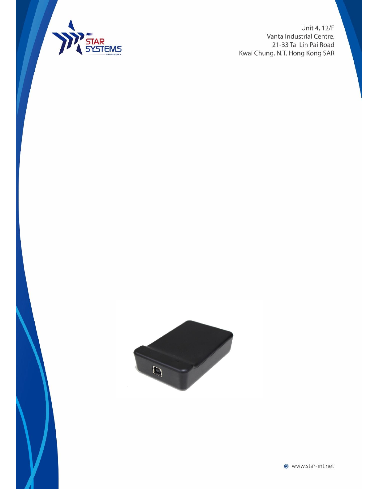
The Ranger is a new compact, full-featured ISO18000-6C/EPC C1G2 reader which is perfect
for use in a variety of tag reading, writing and programming applications.
Ranger is powered by a standard USB connection (requires USB 2.0 or above), no additional
power supply is needed. Its small size allows it to easily be used on a desktop or where
space is limited.
The Ranger Reader is very user friendly and extremely easy to set up read and write tags
with its standard free software. It also comes with a SDK to allow you to create your own
custom programs to interface and drive the Ranger Reader.
The Ranger reader’s features provides a powerful, and very economical way to implement
UHF RFID technology in just about any application.
Possible Applications:
Point of Sale RFID reading and writing
Commissioning/Activation of RFID Tags
Parking and Access Control
Production / WIP checkpoints
Document Tracking and Management
Library Management
Catering Management
Healthcare/Pharmaceutical Applications
The reader has 2 LEDs as status indicators. The LEDs provide indication for the following:
Status \ LEDS
Blue
Red
Connected to Host
Off
On
Tag read/write operation
Flash
On
3
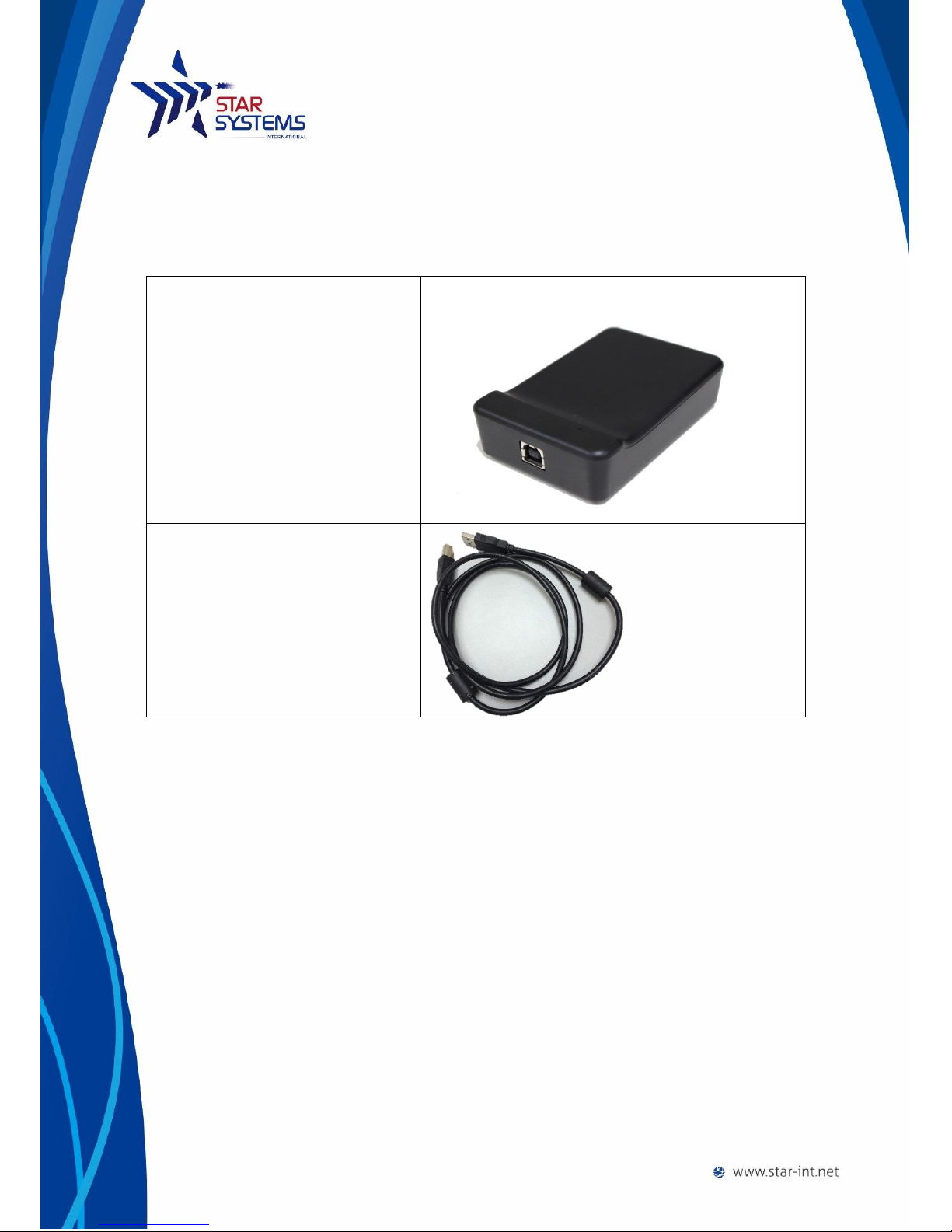
Package Content
Ranger Reader x 1
USB Cable x 1
Installing the reader
The reader is intended to work on a desktop environment. We recommend to operate
the reader on a NON-Metal desktop surface. Since metal cause reflection of RF, and may
cause undesirable performance of the reader.
Mechanical installation
Connect the USB cable to the reader and to the host PC. The reader requires USB 2.0 or
above to operate on a PC.
The reader’s LED should turn on upon successful connection.
Software installation
The reader requires installation of driver to function properly.

4
System requirement
64 MB Ram
200 MB of Harddisk space
Windows 2000, Windows Vista, Windows 7 and Windows 8
Driver installation
The Ranger Reader use serial protocol to communicate with host PC. In order for the host PC to be
able to communicate with the reader, it may be necessary to install the USB to serial driver.
1. Unzip “CP210x_VCP_Windows.zip”
2. If your operating system is running 64bits, run“CP210xVCPInstaller_x64.exe”Otherwise if ,
your operating system is running 32bits, run“CP210xVCPInstaller_x86.exe”.
3. Follow the on screen instruction of the installer.
Ensure the reader is connected properly
1. Go to Control Panel > Device Manager
2. Open tab(COM 和LPT)”,
3. You should see “CP201x USB to UTRA bridge(COM X)”where X is the port number
assigned by the PC

5
Troubleshooting
If you cannot see the “CP201x USB to UTRA bridge” in device manager, ensure the USB cable
connect to the reader properly and the reader LED is on.
If you see a (!) symbol at the side of the “CP201x USB to UTRA bridge” in device manager, this
indicates that the PC is not able to run the driver properly. You can try:
1. Re-install the driver as it may be corrupted.
2. Connect to another USB port of the PC.
Using the reader
Tag placement
To ensure the tag read and write operations can be perform with a consistent performance, please
ensure to place the tag’s whole inlay within the surface of the reader.
Running the demo software
Connect the reader to the PC using the USB cable before running the test tool.
Upon successful connection of the test tool with the reader, you will be able to hear two beeps from
the reader. A pop up window will be shown as followed:

6
If the software failed to connect to the reader automatically, you will see a pop up error message:
In case where the software failed to automatically connect the correct com port, you can manually
input the com port to connect to.
1. Go to Settings
2. Go to the “Com” tab
3. Change the value of the “Serial Ports”*
**You can go to Window> Control Panel>Device Manager to check the Com Port number that the
reader is using, please refer to section driver installation section.

7
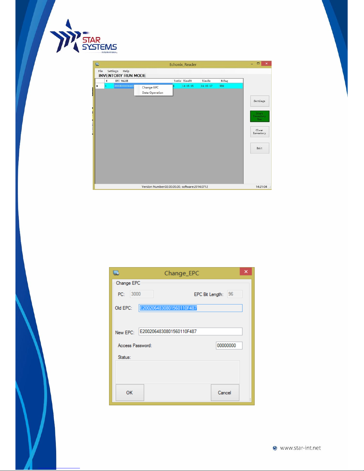
Reading tags in Inventory Mode
At the main page, click “Start Inventory” Button, information on tag being read will be displayed in
the center of the screen as a list. If multiple tags are being read, multiple records will be shown.
To stop the reader from reading tags, click “Stop Inventory Run” Button.
To clear the tag data read, click “Clear Inventory” button.
Tag Memory Management
To perform read/write operation on individual tag’s memory banks, right click on the tag data record
to bring up the option Menu.
8
Change EPC
To change EPC click on the Change EPC option and a window will pop up.
Input the new EPC and access password (if necessary).
Finally click ok to confirm the change, the reader will write the new EPC
to the tag.
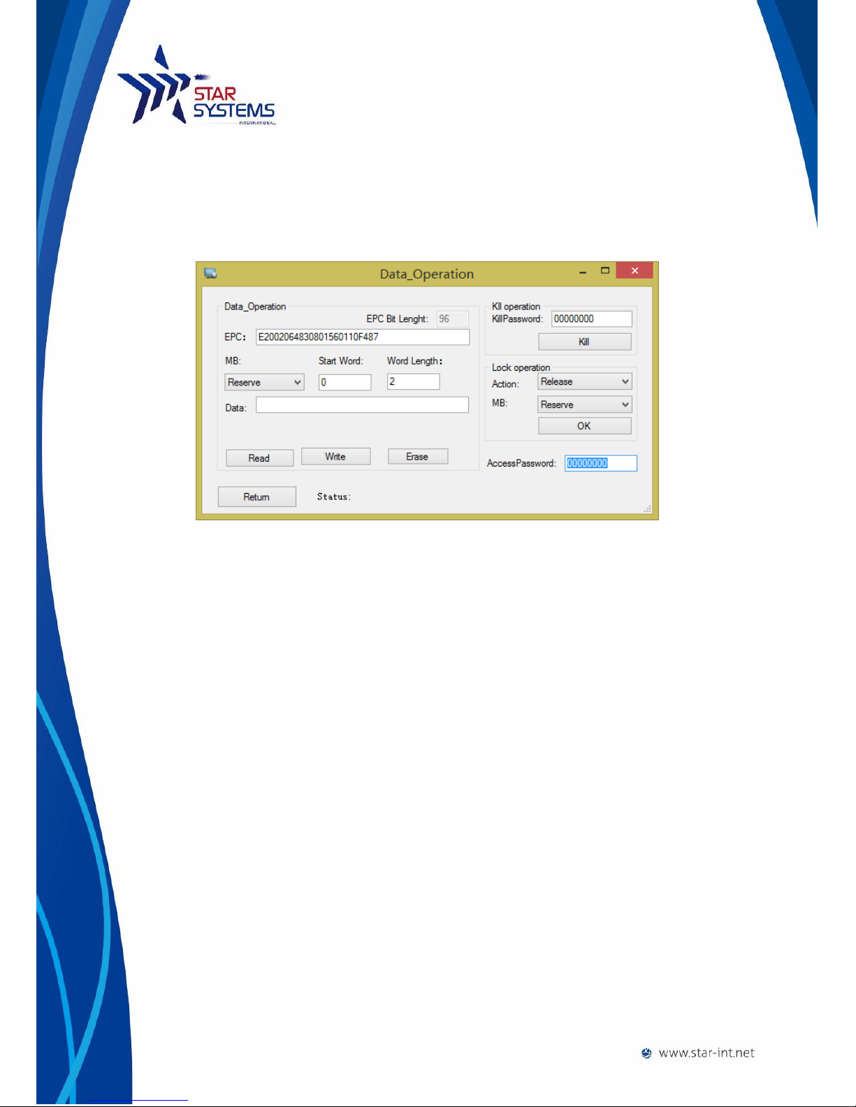
Tag memory banks data operation
9
To read/write other memory banks of the click on Data Operation option. A
new window will pop-up.
Select different memory banks to read/write.
Tag locking operation can also be performed in this window.
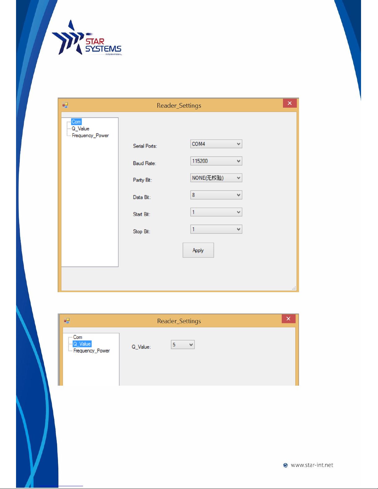
Reader Settings
To change settings of the reader, click on the setting buttons on the right to bring out the setting
menu. There are 3 tabs in the pop-up menu that user can choose from.
10
Communication setting
Serial port communication setting can be configured in this tab.
Q-Value Setting
Q-Value setting of the reader can be configured
Frequency Power Setting
This tab allow user to change the output power of the reader.

11
Reader Specification
Power: 5V , no battery (USB power)
Working Frequency: 902-928MHz
Input Voltage: DC 5V
Maximum Power Output: 20mW
Storage Temperature: -45°C~ +95°C
Operating Temperature: -20°C~ +65°C
Dimensions: 105 * 70 * 25mm
Weight: 75g
Regulatory Compliance: FCC
Supported protocol: ISO 18000 6C, EPC C1G2
Warranty Terms
The warranties for GTSYS products are set forth in the limited warranty terms accompanying such
products. Nothing herein should be construed as constituting an additional warranty. The warranty
is valid, if and only if the user of the product operate it as instructed by this document or otherwise
by Star System International Limited’s personnel. Failure to comply with the instructions may cause
damage to the product or harm to the users. Usage of third party accessories (including USB cable)
may cause the reader to not function as intended. In circumstances where but not limited to:
damage is caused by misuse of the reader, unauthorized modification of the reader, warranty may
be void.

12
Disclaimer and Limitation of Liability
Under no circumstance that Star System International Limited shall be responsible for the
damage caused by misuse of the product or usage of the product in applications that it is
not designed for.
This product is not designed, intended, authorized or warranted to be suitable for life
support applications or any other life critical applications which could involve potential risk
of death, personal injury, property damage, or environmental damage.
Star System International Limited shall not be liable for technical or editorial errors or
omissions contained herein of for incidental or consequential damages in connection with
the furnishing, performance, or use of this material.
Microsoft, Windows, the Windows logo are trademarks of Microsoft Corporation in the
U.S. and other countries. All other products names mentioned herein may be trademarks of
their respective companies.
Regulatory Compliance
Changes or modifications to this unit not expressly approved by the party responsible for compliance
could void the user’s authority to operate the equipment.
NOTE:
This equipment has been tested and found to comply with the limits for a Class Bdigital device,
pursuant to Part 15 of the FCC Rules. These limits are designed to provide reasonable protection
against harmful interference in a residential installation. This equipment generates, uses and can
radiate radio frequency energy and, if not installed and used in accordance with the instructions,
may cause harmful interference to radio communications.
However, there is no guarantee that interference will not occur in a particular installation. If this
equipment does cause harmful interference to radio or television reception, which can be
determined by turning the equipment off and on, the user is encouraged to try to correct the
interference by one or more of the following measures:
Reorient or relocate the receiving antenna.

13
Increase the separation between the equipment and receiver.
Connect the equipment into an outlet on a circuit different from that to which the receiver is
connected.
Consult the dealer or an experienced radio/TV technician for help.
This device complies with Part 15 of the FCC Rules. Operation is subject to the following two
conditions:
(1) This device may not cause harmful interference, and
(2) This device must accept any interference received, including interference that may cause
undesired operation.
Star Systems International Ltd.
+852 3691 9925
Unit 04, 12/F Vanta Industrial Centre
21-33 Tai Lin Pai Road, Kwai Chung
Hong Kong
- End -
Table of contents


