Star LCS880-008 Quick guide
PLITSTR309 REV. L 5/13/14
INSTALLATION AND INSTRUCTION MANUAL
SIREN AMPLIFIER & HAND-HELD LIGHT CONTROLLER
LCS880-008 & LCS881-8

-i-
Please Note: These instructions are provided as a general guideline only. Some
vehicles may require special mounting, wiring, and/or weather-sealing. This is the
sole responsibility o the installer. Star Headlight & Lantern Co., Inc. assumes no
responsibility for the integrity of the installation for this or any of its products.
MODEL: LCS______________________
PURCHASE DATE: _______________
DEALER: __________________________
INSTALLER: _______________________
INSTALLATION DATE: ____________
AMPLIFIER SERIAL #: _______________
CONTROL HEAD SERIAL #:________________
ARROWSTICK OX SERIAL #:______________
SIREN OPTION DIP SWITCHES
_____ Negative uxiliary Switching
_____ Negative Park Kill Switching
_____ Two-Tone Enabled
_____ Phaser Disabled
_____ Slide Switch Pursuit Disable
CONTROL HEAD OPTION JUMPERS
_____ udible Beep disable
_____ S4 ctivates S1+S2+S3
_____ Momentary S3
_____ 8 sec. gun lock (S4)
_____ uxiliary = Manual
_____ Wail Tone uto- ctivate
_____ TD W RN uto- ctivate (LCS881 only)
ARROW STICK OPTION JUMPERS
(LCS881 ONLY)
_____ Phantom Mode
_____ Fast rate arrow
_____ Low power (Dim)
_____ 6 head arrow (1 & 8 flash)
_____ 8 head arrow
_____ Group 2 Traveling arrow
_____ Double blink end arrow
Installation In ormation

-ii-
(Installation In ormation CONT’D)
IMPORTANT: Please read all o the ollowing instructions be ore installing
your new light. Failure to ollow these sa ety precautions
may result in damage to your light or vehicle and may result
in serious injury or death to you and your passengers.
Important
: This product is used to warn traffic. Improper use may result in vehicular
collision, personal injury and/or death. Star Headlight & Lantern Co., Inc., and its
subsidiaries shall not be held responsible for damages directly or indirectly caused by
improper use of this product.
NOTICE
Due to continuous product improvements, we must reserve the right to change any specifications and
information, contained in this manual at any time without notice. Star Headlight & Lantern Co., Inc. makes no
warranty of any kind with regard to this manual, including, ut not limited to, the implied warranties of
merchanta ility and fitness for a particular purpose. Star Headlight & Lantern Co., Inc. shall not e lia le for
errors contained herein or for incidental or consequential damages in connection with the furnishing,
performance, or use of this manual.
S1
S2
S3
S4
PUSH
BUTTON
SWITCHES
SLIDE SWITCH
PUSH BUTTON SWITCH FUNCTIONS
POSITION 2
L2
L1
SLIDE SWITCH FUNCTIONS
L1 L1
L2
L3
POSITION 1 POSITION 3
Use this chart to label the function of your switches.
S ME S IN POSITION 1 S ME S IN POSITION 1 & 2
S ME S IN POSITION 2
S1 S2
S4S3
OFF L1 L2 L3

-iii-
Table o Contents
INSTALLER INFORMATION i-ii
GENERAL DESCRIPTION 1
INSTALLATION NOTES 2
INSTALLER SELECTABLE OPTIONS 2-8
Siren Option DIP Switches 3-5
Control Head Option Jumpers 6-8
MOUNTING 9-10
Siren mp & Relay Control Box 9
Cradle Mounting 9
rrow Stick Control Box 10
ELECTRICAL CONNECTIONS 11-17
Wire Size nd Termination 11
Siren mplifier 11-14
Siren Wiring Diagram 13
Horn Ring Transfer Wiring Diagram 14
RFI Reduction and RFI Choke Installation 15
Input Power and Switch Output Connections 16-17
Light Wiring Diagram 17
ARROW STIC SETTINGS AND CONNECTIONS 18-22
rrow Stick Option Jumpers 18-19
rrow Stick Wiring 20-22
LABEL INSERTION 22
OPERATION 23-26
General 23
Slide Switch 23
Push Button Switches 23
Siren Mode Buttons 24
Microphone 25
P Volume 25
rrow Stick Controls 25
Speaker Diagnostics 25
Radio Repeat Volume 26
uxiliary Input 26
Park Kill 26
Fuses 26
SERVICE 27-30
Troubleshooting 27
Parts 28
Specifications 28
Warranty 29
Returned Materials uthorization (RM ) Form 30
FLANGED CONTROL HEAD TEMPLATE 31

-1-
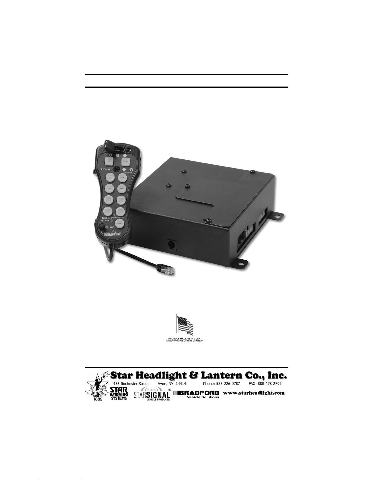
General Description
The LCS880 series is a premium remote system that combines the siren amplifier, the
siren controls, and light controls all in one system. A single slim-line hand-held remote
control head combines the noise-canceling microphone with a built in siren, as well
as many of the switch and light controls for the ehicle. The control head contains
illuminated buttons that change color to indicate status. The face of the hand-held
controller is sealed around e ery push button to help pre ent liquid from entering
the electronics. The amplifier is a 200W siren amplifier unit designed for single or dual
100W speaker use. The LCS881 model adds an additional button for full arrow stick
control.
The hand-held controller contains se eral distinct controls for operation of ehicle
de ices. The slide switch allows quick pursuit mode operation. The far right slide
position can be set up to acti ate maximum lights and siren for pursuit mode. There
are six push buttons to operate the siren and four push buttons to control four
different lighting or auxiliary functions. The LCS881 also adds an additional button for
control of an arrow stick.
The LCS880 series is designed to allow maximum ersatility in mounting. The hand-
held controller is remote from the siren amplifier and light relay control box, creating
a compact user interface that can be mounted onto the dashboard, o erhead, or
in the center console. The hand-held controller comes with a cradle for mounting.
The amplifier box and arrow stick control box can then be mounted remotely in the
trunk, under the dashboard, under the seat, or where er con enient.
Siren operating modes include Wail, Yelp, Phaser, and Radio. A Noise Canceling PA
O erride is a ailable in all modes. A Manual button allows tone toggle operation
and manual siren control. The Air Horn button will o erride any siren tone. The
ehicle horn switch may also perform the Manual push button function ia an
auxiliary input. Ten option jumpers allow the unit to be fully customized to the
operators' needs. Options include: Phaser s. Two-Tone, Phaser disable, 8 second
timed gunlock release, and momentary s. lock-on/lock-off switch operation. A Park
Kill option is pro ided for connection to a door switch, etc. to disable the siren when
exiting the ehicle. Both a PA olume and a Radio olume are pro ided.
The LCS880 series has been designed with se eral protection features to pro ide
exceptional field ser ice. Excessi e high or low oltage detection will disable the
siren output, protecting both the amplifier and the speaker. Fused inputs pro ide
safety against re erse polarity. Speaker diagnostics pro ides user feedback as well
as shutdown protection against speaker opens and shorts. The first four light output
functions are indi idually protected with 20A fuses, while the Horn Ring Transfer (HRT)
output function is protected with a 2A in-line fuse. CAUTION: These protection
features will not guard against o erloading the outputs.
The LCS880 series is a ailable in the following different ersions:
LCS880-008 Standard ersion with slide switch, full siren controls, and light
controls. Includes a remote hand-held controller with microphone
and a siren amplifier/switch relay box.
LCS881-008 Enhanced ersion with all the standard controls plus arrow stick
controls. Also includes the arrow stick control box.

-2-
Installation Notes
Proper installation of the unit is essential for years of safe, reliable operation. Please
read all instructions before installing the unit. Failure to follow these instructions can
cause serious damage to the unit or ehicle and may oid warranties.
Qualifications - The installer must ha e a firm knowledge of basic electricity, ehicle
electrical systems, and emergency equipment.
Keep These Instructions - Keep these instructions in a safe place for future reference.
Ad ise the ehicle operator of the location.
Contents should include:
1 - and eld Controller
1 - Amplifier and Light Control Box
1 - Amplifier Wire arness with Connector
1 - 25’ Amplifier Communication Cable (6-wire telephone style cable)
1 - Extended Cable Adapter
1 - Mounting ardware
1 - Label Set
1 – RFI Filter
1 - Installation and Operating Instructions
1 – TDC850 Arrow Stick Control Box (LCS881 models only)
1 - Arrow Stick Communication Cable (telephone style cable) (LCS881 models only)
1 - Communication Cable Splitter (LCS881 models only)
1 – 12” Communication Cable (LCS881 models only)
Installer Selectable Options
The LCS880 and LCS881 ha e se eral options that can be selected during
installation. Jumpers and DIP switches on the printed circuit board inside the
amplifier case, inside the control head, and inside the arrow stick control box
(LCS881 only) allow the installer to select these arious options. These options should
be set before installation of the unit.
Siren Option DIP Switches (located in the amplifier case):
• Auxiliary input polarity
• Park Kill input polarity
• Two-tone replacement of Phaser tone
• Phaser Disable
• Slide Switch Pursuit Disable
Control ead Option Jumpers (located inside the control head)
• Audible beep disable
• Button S4=S3+S2+S1
• S3 = Momentary switch
• 8 second timed gun lock release (S4)
• Auxiliary control (Manual s. Horn)
• WAIL Tone Auto Acti ate on Position L3 of Slide Switch
• Arrow Stick WARN Auto Acti ate on Position L3 of Slide Switch

-3-
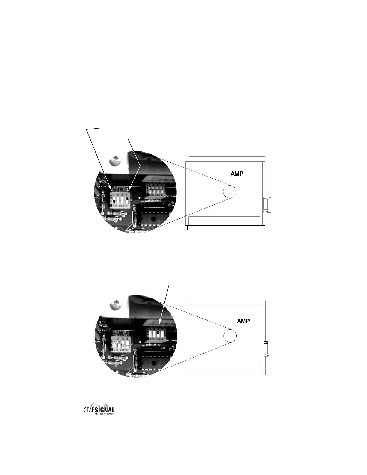
SIREN OPTION DIP SWITC ES
Amplifier Cover Removal
C UTION:
DO NOT OVER
TIGHTEN SCREWS!
Loosen the three protruding
Philips head screws located on
the top of the amplifier unit. Slide
the co er off.
(Installer Selectable Options CONT’D)
Auxiliary Input Polarity
Applying a positi e oltage to the green wire normally acti ates the auxiliary
function (Air Horn standard/MANUAL function optional).
The wiring diagram on page 13 shows both connection examples.
To instead ha e the AUX function acti ate when the green wire is connected to
ground (negati e) .
1. Turn “AUX POS” DIP switch off.
2. Turn “AUX NEG” DIP switch on.
Diagram showing NEG AUX set up
-4-
(Installer Selectable Options CONT’D)
The Park Kill (Cutout) Input turns off any siren tone output when acti ated, and
remains off until a control is acti ated or changed. The wiring diagram on page 13
shows two connection examples.
Connecting the white wire to positi e (+12 VDC) normally acti ates the Park Kill
input. To instead ha e it acti ate when the white wire is connected to ground
(negati e):
1. Turn “PK POS” DIP switch off.
2. Turn “PK NEG” DIP switch on.
Park Kill Input Polarity
Two-Tone
If desired, the Phaser sound can be replaced with a Two-Tone sound. This can be
done by turning on (up position) DIP switch #3 in the amplifier (labeled SW).

-5-
(Installer Selectable Options CONT’D)
Phaser Disable
The Phaser function can be completely disabled by turning on (up position) DIP
switch #4 in the amplifier (labeled PD). This will also disable the M N button while
the siren is in Phaser mode (which normally would produce a Two-Tone sound).
Pursuit Disable
Slide switch position 3 normally acti ates:
• All three light functions (L1, L2, & L3)
• The siren (into the Wail mode)
• Warn pattern on the Arrow Stick (LCS881 series only)
To disable the automatic acti ation of the siren and Arrow Stick, mo e DIP switch #2
in the amplifier (labeled PS) to the “UP” position.

-6-
(Installer Selectable Options CONT’D)
CONTROL EAD OPTION JUMPERS
Fi e jumpers located inside the hand held controller can be used to select arious
options. Re iew the chart below to determine if you want to change any of the
default settings.
Jumper
Standard Setting
(jumper on both pins)
Optional Setting
(jumper only on one pin)
S4 Timer
Push button S4 is a standard
ON/OFF button.
S4 used for Gun Lock - Stays
acti ated for only 8 seconds when
pressed.
Auxiliary Control
(Horn vs. Manual)
The green auxiliary (AUX) wire in
the siren amplifier harness is
connected to the ehicle horn
ring, and acti ates the siren’s AIR
HORN for all siren modes except
RADIO.
AUX wire duplicates the function of
the MAN push button instead of the
HORN.
Momentary (S3)
Push button S3 is a standard
ON/OFF button.
S3 becomes a momentary switch,
thus only being acti e while being
held in.
Traffic Director
WARN Pattern
Auto-Activation With
Slide Switch
The WARN pattern on your Traffic
Director will auto-acti ate in slide
switch position 3 (L3)
TD WARN pattern auto-acti ated in
L1 or L2.
TD WARN pattern NOT acti ated in
L3
S4=S3+S2+S1
(LCS880 ONLY)
S4 is an independent switch
controlling output S4.
When pressed, S4 automatically
acti ates S3, S2, and S1 buttons.
Audible Beep
Disable
An audible beep is heard when
the buttons in the control head
are pressed.
No beep when the buttons in the
control head are pressed.
WAIL Tone
Auto-Activation With
Slide Switch
WAIL tone auto-acti ated in slide
switch position 3 (L3)
WAIL tone auto-acti ated in L1 or L2,
WAIL tone NOT acti ated in L3
Jumper
Standard Setting
Optional Settings
(Programmed with PROGR M
jumper removed)
S4=S3+S2+S1
(LCS88 ONLY)
S4 is an independent switch
controlling output S4.
When pressed, S4 automatically
acti ates S3, S2, and S1 buttons.
Jumper Controlled Options
Programmable Options (LCS88 ONLY)
-7-
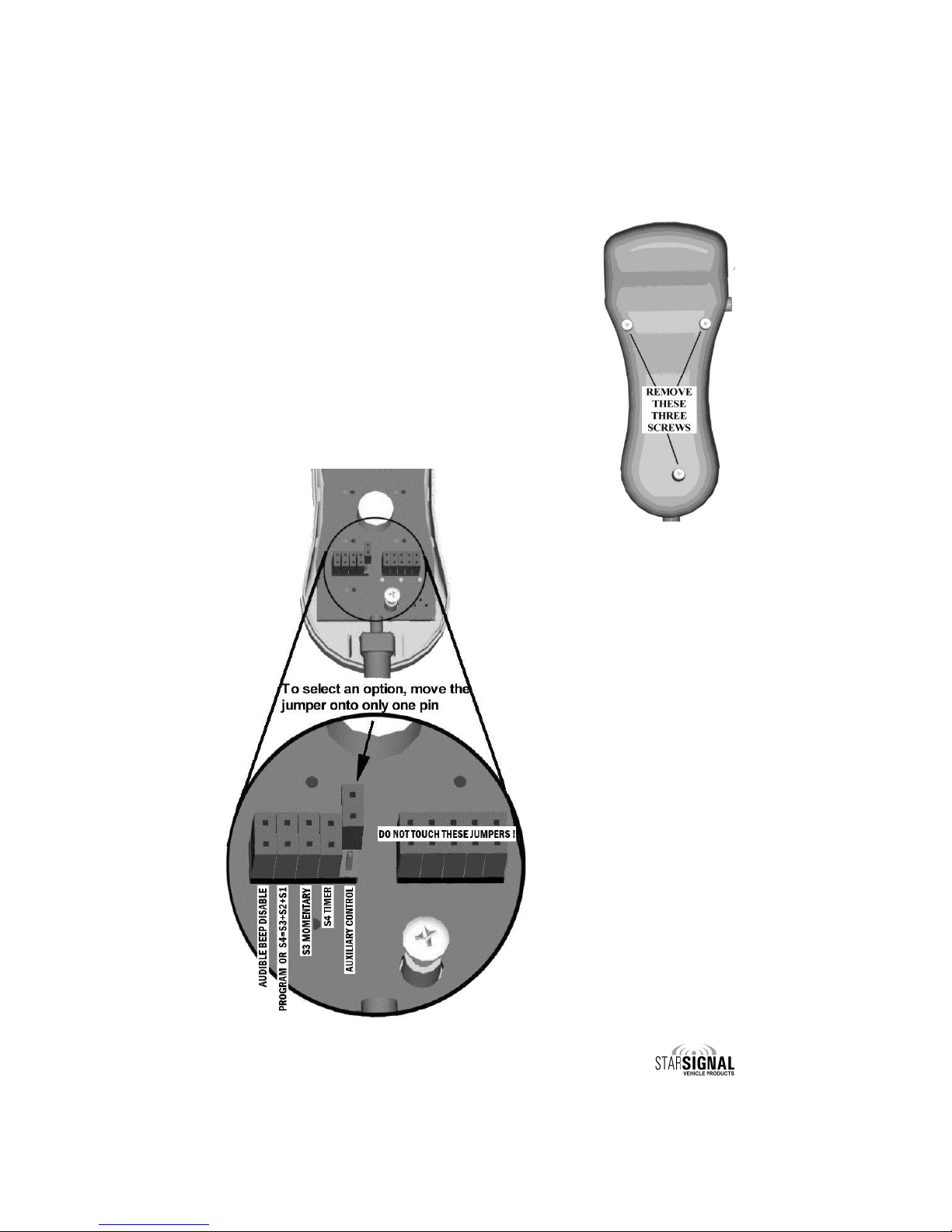
Control ead Cover Removal
• Remo e the three Philip head screws recessed in the
back of the hand held controller.
• CAREFULLY remo e rear co er using caution so as not to
lift circuit board and membrane switch away from front
faceplate.
• Locate the 10 jumpers located near the microphone coil
cord strain relief.
• DO NOT REMOVE NY OF THE FIVE JUMPERS ON THE RIGHT
SIDE !!!
• By default, the fi e jumpers on the left side come installed
across both pins.
(Installer Selectable Options CONT’D)
Jumper Controlled Options
To change any of these options, mo e
the corresponding jumper from both
pins to only the top pin as shown in the
diagram to the left.
•
udible Beep Disable
•
S4=S3+S2+S1 (LCS880 only)
•
S3 Momentary
•
S4 Timer
•
uxiliary Control
If you are NOT changing any of the options described on the
pre ious page, skip this section.

-8-
Programmable Options (LCS88 ONLY)
•
S4=S3+S2+S1
•
W IL Tone uto- ctivate By Slide Switch
•
TD W RN uto- ctivate By Slide Switch
The LCS881 has a number of additional programmable option that are NOT
a ailable in the LCS880. To program these options:
• Power up the unit and remo e the PROGRAM jumper.
• With the slide switch in the OFF position, toggle PB4.
Red : S4=S3+S2+S1
Green: S4= Standard On Off Switch
• Mo e the slide switch to positions L1, L2, and L3.
• Toggle the WAIL button to program whether or not you want the WAIL tone to
auto-acti ate whene er the slide switch is in each of those positions during
normal operation.
• Toggle the LRCO button to program whether or not you want the Traffic
Director to auto-acti ate into a WARN pattern whene er the slide switch is in
each of those positions during normal operation.
Red : Enabled
Green: Disabled
(Installer Selectable Options CONT’D)
-9-
Mounting
SAFETY PRECAUTIONS
For the safety of the installer, vehicle operator, passengers, and the community
please observe the following safety precautions. Failure to follow all safety
precautions and instructions may result in property damage, injury or death.
DO NOT mount in air bag deployment area.
Devices should be mounted only in locations listed in SAE standard J1849.
Controls should be placed within convenient reach of the driver.
Assure clearances before drilling in vehicle.
Sound levels produced by attached speakers can cause permanent hearing loss.
Never operate this unit without adequate hearing protection for you and others in
the area.
(OS A 1910.95)
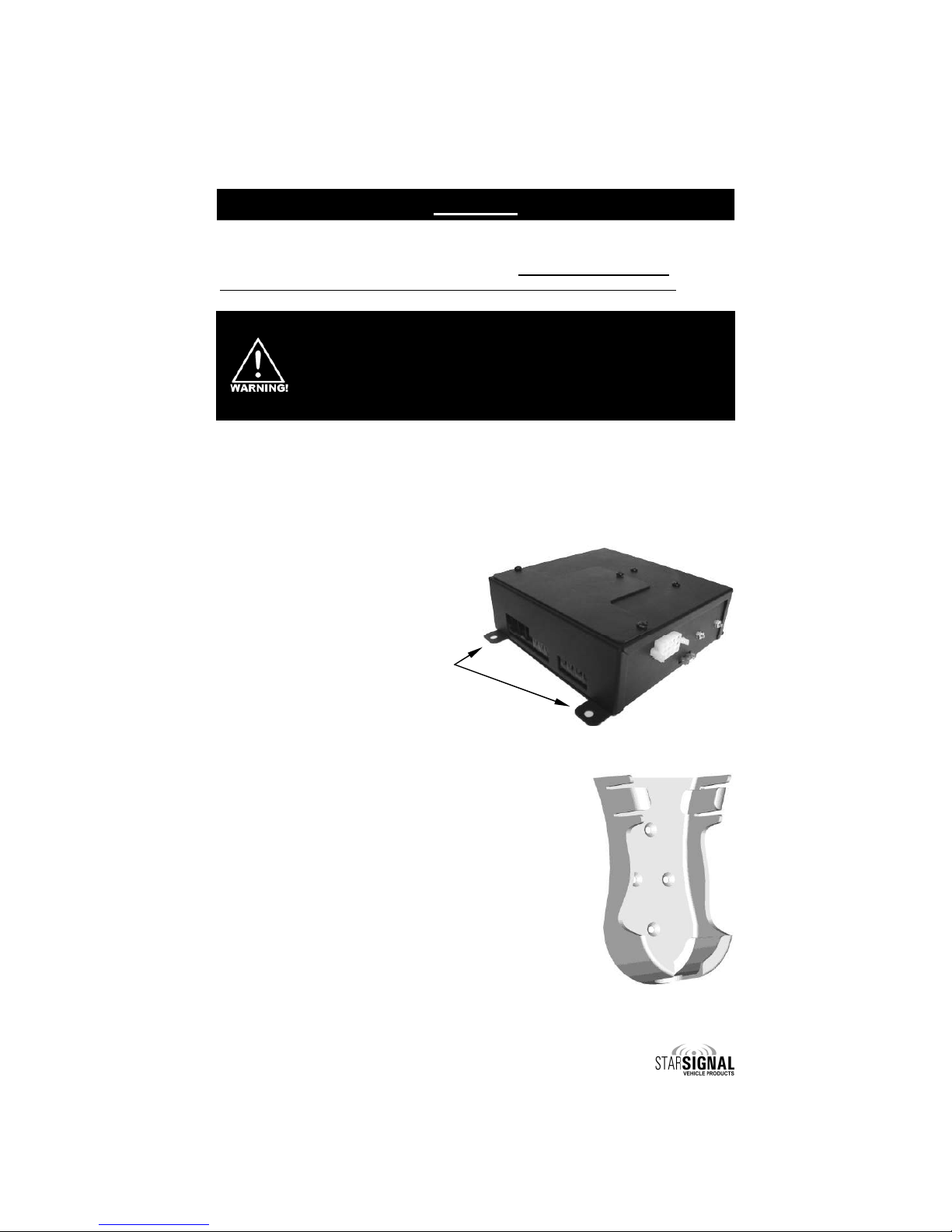
SIREN AMPLIFIER & RELAY CONTROL BOX
• The amplifier should be mounted in a location such as the dri er compartment
firewall, under the seat, or in the trunk.
• Do not mount the amplifier in the engine compartment or in an area that would
be allowed direct exposure to weather elements.
• Choose a mounting location away from any air
bag deployment areas.
• Assure adequate entilation to pre ent
o erheating.
Mount the amplifier unit through the
four 1/4” holes located in the flanges
(two isible and two not shown in the
picture to the right).
CRADLE MOUNTING
• The LCS880 and LCS881 both include a cradle for
storing the hand-held controller when it is not in use.
• Select a location so that the cable does not interfere
with the ision of the dri er or the operation of any
controls, including, but not limited to, the steering
wheel, gear shifter, and/or airbag.
• The cradle comes with four mounting holes predrilled
in it. Only two screws are normally necessary to
secure the cradle to the dash. Once you ha e
selected a location, use the cradle as a template
and mark the two mounting holes you will be using.
• Carefully drill two 1/16" pilot holes for your screws. Be
sure to check for wiring and/or any other obstructions
behind the mounting hole locations.
• Once the holes are drilled, use the two self-tapping
Phillip head screws to secure your cradle.

-10-
(Mounting CONT’D)
ARROW STICK CONTROL BOX MOUNTING
(MODEL LCS881 only)
• Review the Arrow Stick Settings and Connections (pages 8-22) section for
details on any option jumper settings prior to installing this control box.
• The TDC850 arrow stick control box is usually mounted near the siren amplifier
and relay control box in a location such as the dri er compartment firewall,
under the seat, or in the trunk.
• Do not mount the amplifier in the engine compartment or in an area that would
be allowed direct exposure to weather elements.
• Choose a mounting location away from any air bag deployment areas.
• Assure adequate entilation to pre ent o erheating.
• The arrow stick controller comes with a 7-foot communication cable that must
be plugged into the siren amplifier.
• A “U” bracket is pro ided for mounting. The “U” bracket may be used as a
template when locating and drilling mounting holes.
-11-
Electrical Connections
RECOMMENDED WIRE SIZE, AMP CAPACITY & CONSTRUCTION
Ampacity Range SAE Wire Size Gauge/No. of Strands
5A - 10A #16 29/19
10A - 15A #14 27/19
15A - 30A #12 25/19
30A - 40A #10 23/19
40A - 50A #8 21/19
WIRE SIZE AND TERMINATION
• The wiring diagrams on pages 13 and 17 show the minimum wire size used for
each connection, along with recommended lead color.
• If the wire is longer than 10 ft., use the next larger wire size.
• Use only high quality crimp connectors.
• Make sure all connections are tight.
• Route wiring to pre ent wear, o erheating and interference with air bag
deployment.
• Use grommets and sealant when passing through compartment walls.
• Minimize the number of splices to reduce oltage drop.
• Ground connections should be made directly to the negati e of the ehicle
battery. If not possible, connect only to substantial chassis components.
• Install and check all wiring before connection to ehicle battery. SEE TABLE
BELOW FOR CORRECT WIRE SIZING!
• All conductors should be constructed of stranded copper with thermoplastic
insulation.
CAUTION: All wires should be rated for at least 125% of their maximum current load.
All wires connected to the positive terminal of the battery should be fused at the
battery for their rated load. The load can be calculated by adding all lamp
wattages and di iding by 13. Load (Amps) = Total Watts / 13 olts. Do not use 1/4"
diameter glass fuses, as they are not suitable for continuous duty abo e 20 amps.
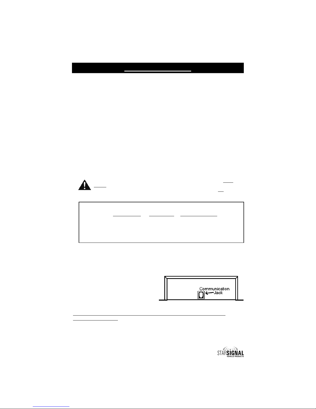
SIREN AMPLIFIER
Communication between the control
head and the amplifier is made ia a
communications cable using an RJ11
jack located on the opposite side of
the power connector. C UTION:
Please note that the cable used IS NOT
a standard telephone cord and
C NNOT be replaced with one.
Make all electrical connections to the power connector before installing the
connector on the unit.
If the unit needs ser ice, both the communication cable and the power connector
can be easily remo ed without unwiring the connector.

-12-
(Electrical Connections: Siren Ampli ier CONT’D)
Siren electrical power connections to
the amplifier are made using a
remo able connector located on the
back of the amplifier case.
The power supply to the siren unit must
be capable of deli ering peak currents up to
50 amps for adequate short circuit protection
and reliable operation. The preferred source
is directly at the ehicle battery. The unit is
internally fused. The wiring diagram on the next page shows detail of how to wire
the connector on the amplifier to the ehicle.
Make all electrical connections to the power connector before installing the
connector on the unit.
Mandatory Siren
Wiring Connections:
BLACK LEADS:
(GROUND) - Connect BOTH black wires to the negati e of the battery, or
to a good chassis ground. Be sure to use minimum size #14 AWG wire.
RED LEADS:
(POWER/+12VDC) - Connect BOTH red wires to the positi e of the
battery, or to a high current power buss. Be sure to use minimum size
#14 AWG wire.
BROWN LEADS:
(SPEAKER) - Connect one lead to each terminal or lead of the speaker.
If connecting a second speaker in parallel, you must observe the polarity
of the speakers (phasing). Be sure that the positive terminals of both
speakers are connected together to the same brown wire from the siren.
PINK LEAD:
(IGNITION SWITCHED POWER) - Connect the pink wire to your ignition-
controlled power (or other switched power source). This will turn the
power to your unit on and off.
Optional Siren Wiring Connections:
BLUE LEADS:
(RADIO REPEAT) - Connect one blue lead to each terminal of the two-
way radio speaker or output connector of the radio. Use #18 AWG wire.
GREEN LEAD:
(AUX) - Use if you would like to acti ate the siren’s AIR HORN when the
ehicle horn is pressed. Connect to horn ring circuit or other remote
switch. Circuit may be positi e or negati e with proper jumper selection.
See Auxiliary Input Polarity section on page 3 for jumper details. NOTE:
Cut lead short if not used & insulate with electrical tape.
Optionally this may be used to mimic the Manual button function when
the ehicle’s horn is pressed. See Auxiliary Control on pages 6-7 for
Control Head jumper setting.
WHITE LEAD:
(PARK-KILL) - Connect to dome light or added door switch. Circuit may
be positi e or negati e with proper jumper selection. See Park Kill Input
Polarity section (page 4) for jumper details.
NOTE: If not used, cut lead short and insulate with electrical tape.
ORANGE LEAD:
(HORN RING TRANSFER or LOW CURRENT OUTPUT) - You only need to
connect this wire if you will also be connecting the green AUX wire to
your horn ring circuit, thus enabling the driver to control the siren
functions by using the vehicle horn. This output is enabled whene er
the handset is acti ated with the recessed On/Off switch on the side
and it temporarily deacti ates the ehicle’s horn. This allows the use
of the horn ring switch without actually sounding the ehicle’s horn.
Connect the Orange wire to the Horn Ring Transfer Relay as shown the
RT Wiring Diagram on page 14.
NOTE: If not used, cut lead short and insulate with electrical tape.
-13-
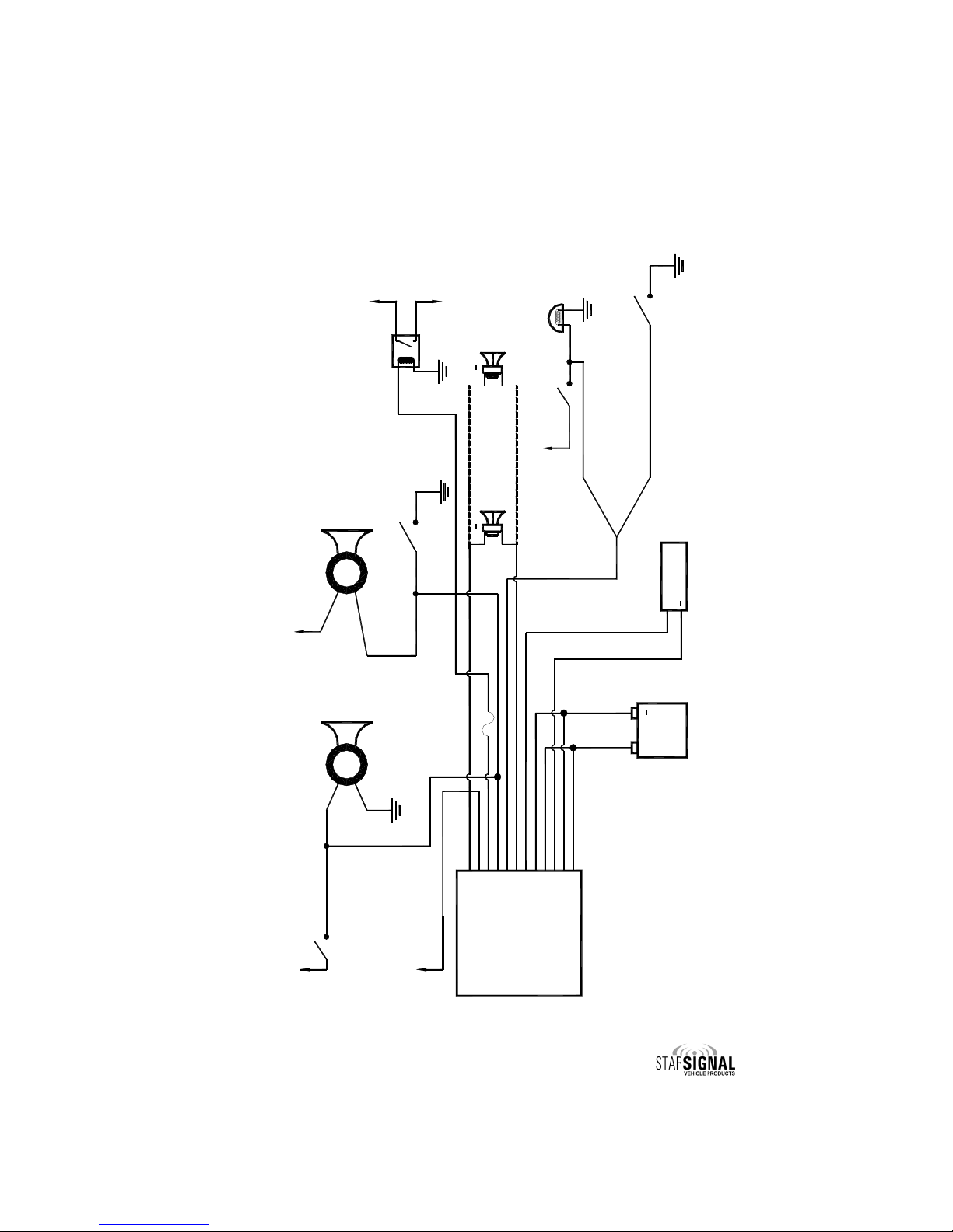
Siren Wiring Diagram
dded Door
Switch
Door Switch Dome
Light
+12 VDC
OR
Negative Switching PK
Jumper Selected
Positive Switching PK
Jumper Selected
R DIO
+
Connect the Blue wires to
the terminals of speaker or
to the output jack of radio
+
B TTERY
OR
Positive
Switching
UX
Negative
Switching
UX
Horn
Switch/Relay
VEHICLE
HORN
OR
Negative Switching UX
Horn Jumper Selected
+12 VDC
VEHICLE
HORN
Positive Switching UX
Horn Jumper Selected
+12 VDC
Horn
Switch/Relay
+12 VDC
+
To High Current Device
+
SPE KER 1
11 OHMS
12 - Brown (#14 WG)
11 - Pink (#18 WG)
10 - Orange (#18 WG)
9 - Green (#18 WG)
8 - White (#18 WG)
7 - Brown (#14 WG)
6 - Blue (#18 WG)
5 - Black (#14 WG)
4 - Red (#14 WG)
3 - Blue (#18 WG)
1 - Red (#14 WG)
2 - Black (#14 WG)
+12 VDC
Ignition controlled
power or other
switched power source
SIREN
MPLIFIER
2 mp fuse
Optional Relay For Horn Ring
Transfer or Other High Current
Device ( ctivated When
Hand-Held Controller Power
Switch is Turned On)
SPE KER 2
11 OHMS
(OPTIONAL)
(Electrical Connections: Siren Ampli ier CONT’D)

-14-
(Electrical Connections: Siren Ampli ier CONT’D)
Ground Side
Horn Switch
Negative Switching
UX Jumper Selected
+12 VDC
VEHICLE
HORN
Cut your horn wire
here and insert the
installer supplied relay
Positive Side
Horn Switch
Connect like
this for
Positive Side
Horn Switch
Connect like
this for
Ground Side
Horn Switch
OR
VEHICLE
HORN
Cut your horn wire
here and insert the
installer supplied relay
Green Wire From mp
Orange Wire From mp
Orange Wire From mp
Green Wire From mp
Positive Switching
UX Jumper Selected
2 mp fuse
+12 VDC
2 mp fuse
User Supplied Optional SPDT Relays
(Opened When Recessed On/Off
Switch On Handset is Activated)
Wiring Diagram for OPTIONAL
Horn Ring Transfer (HRT)
Use this wiring diagram i you are connecting the Orange wire to utilize the Horn Ring
Trans er Feature. This eature de-activates the vehicle horn when the handset is
activated with the recessed On/O switch on the side. The diagram below shows wiring
or both positive and ground-side switched horns, using an installer-supplied relay.

-15-
RFI REDUCTION AND RFI C OKE INSTALLATION
The following steps are recommended when installing, to help reduce RFI:
1. Make sure that both the control head and amp are securely attached to good
chassis ground (i.e. no paint in-between the chassis and the grounding
terminal).
2. Keep the siren control head and amplifier as far away from the police radio as
is practical.
3. Check that the police radio antenna wire makes a right angle from the back of
the police radio and runs on one side of the ehicle. The communications
cable for the siren should make a right angle out of the back of the control
head and exit in the opposite direction from both the police radio antenna wire
and the police radio power wires.
4. Excess communication cable from the control head to the amp should be
tightly bound back near the amplifier box.
5. One of the RFI chokes (STAR P/N: P30039-57) should be placed around the
communications cable at the back of the siren amplifier box.
6. The second RFI choke should be placed around the Red and Black wires exiting
the siren amplifier box.
SIREN CONTROL
HE D R DIO
B TTERY
R DIO POWER WIRES
NTENN LE D
SIREN COMMUNIC TIONS C BLE
RFI
CHOKES
SIREN
MP
Minimum 3'
SIREN POWER ND GROUND WIRES
2-W Y
R DIO
MP
(Electrical Connections CONT’D)
-16-
(REFER TO LIG T WIRE DIAGRAM ON NEXT PAGE, AS WELL AS TO WIRE SIZE TABLE ON
PAGE 11 FOR PROPER WIRE SIZES!)
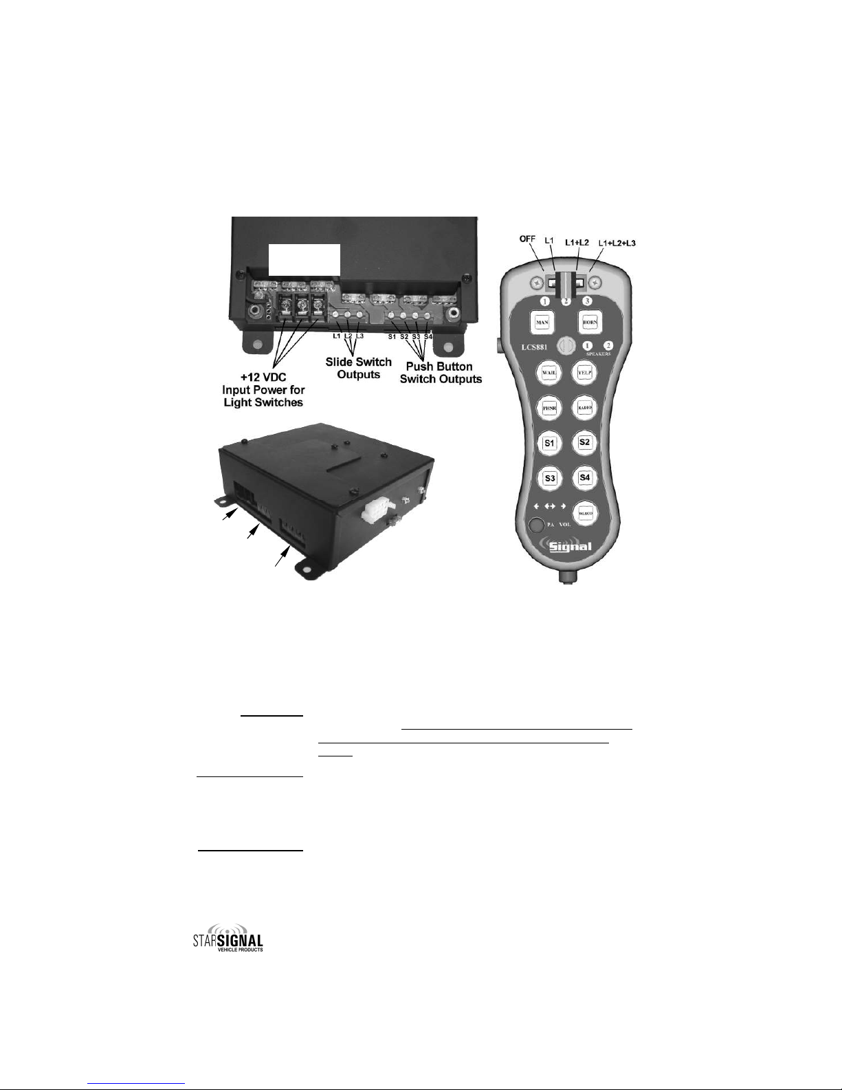
The electrical connections for input power, slide switch outputs, and the push button
outputs are made to the control box (amplifier) using terminal blocks (top diagram
above).
Input Power: (Left Terminal Block) Connect +12VDC to the 3 large barrier
style terminals. When controlling lights with a large amount
of current (>15A) power should be supplied to all three
inputs.
Slide Switch Outputs: (Center Terminal Block) Connect the lights that you wish to
acti ate in the corresponding slide switch positions to the
L1, L2, and L3 outputs (20A max each). (Note: the second
slide switch position activates both L and L2 and the third
slide switch position activates L , L2, and L3).
Push Button Outputs: (Right Terminal Block) Connect the lights that you wish to
acti ate with corresponding pushbutton switches S1-S4 to
the S1-S4 outputs (20A max each).
Top View
(Cover Removed)
(Electrical Connections CONT’D)
INPUT POWER AND SWITC OUTPUT CONNECTIONS
Side View
Input Power
Slide Switch
Outputs
Push utton
Outputs
This manual suits for next models
1
Table of contents
Other Star Automobile Accessories manuals

Popular Automobile Accessories manuals by other brands


Havis-Shields
Havis-Shields Side Slide-Out Step 1997-2007 Chevrolet Full Size Van... installation instructions

Axxess
Axxess AXDSPL-WR installation instructions

Whispbar
Whispbar K496W Fitting instructions

Thule
Thule 77 parts list

Phonocar
Phonocar VM545 instruction manual

Calix group
Calix group MVP 528 Assembly instructions


