EGR EGR-3PVE-COLOUR User manual

TC0123b
page 1 of 28
Holden VE Ute 2007
Part Number: EGR-3PVE-COLOUR
3PC TONNEAU COVER WITH
SPORTS BAR & REMOTE LOCKING
INSTALLATION INSTRUCTIONS
Item
1
2
3
4
5
6
7
8
9
10
11
12
13
14
15
16
17
18
1
1
1
1
2
2
2
8
2
3
2
2
2
2
2
4
4
4
4
4
4
4
2
6
4
12
1
1
8
8
12
1
1
1
1
2
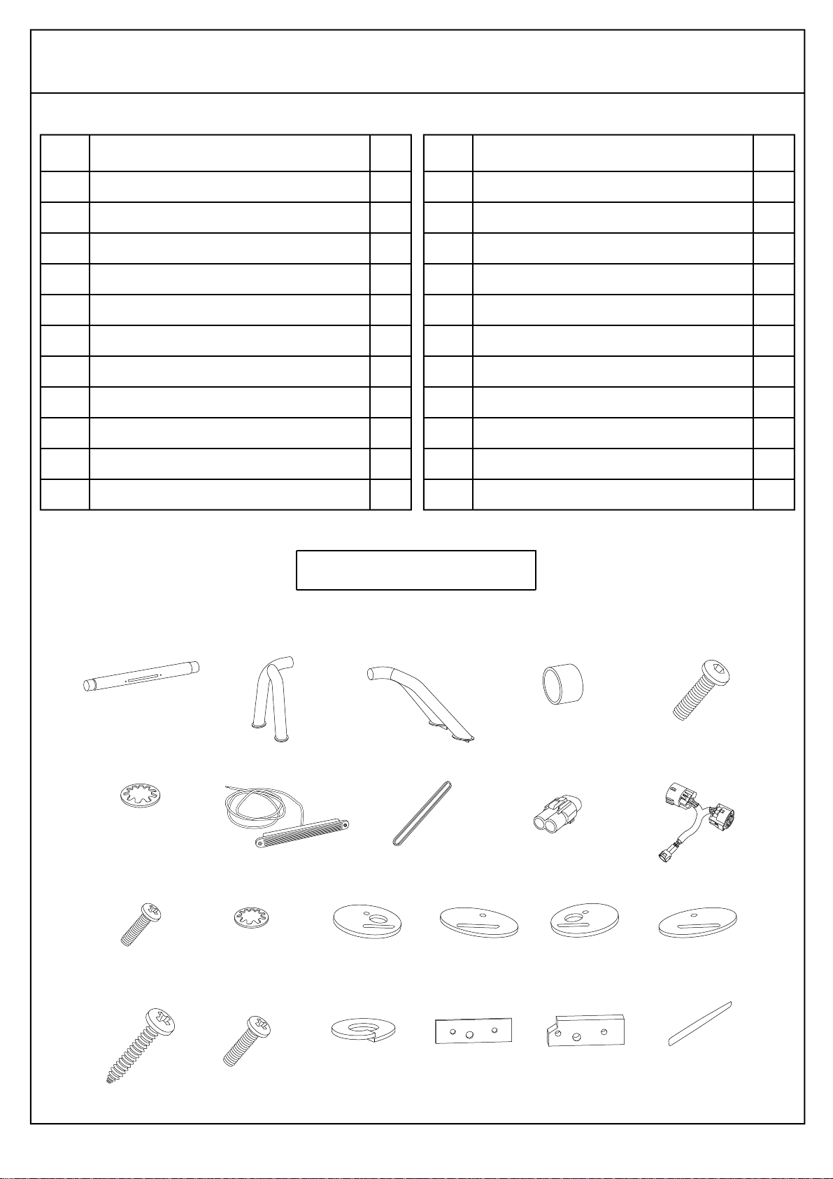
Tonneau Cover
Left Hand Corner Piece
Right Hand Corner Piece
Drill Template
Hinge Base Plates
Hinge Pins
Hinge Pin Locking Tabs
Hex Head Self-tapping Screws
Countersunk Self-tapping Screws
Rubber Extrusion (1xLong, 2xShort)
Gas Strut Brackets
Ball Stud Screws
Lock Striker Brackets
Jacking Brackets
M8 Hex Head Bolts
M8 Hex Nuts
12gx1½” Self-tapping Screws
Plastic Spacers
Component Name Qty Item
19
20
21
22
23
24
25
26
27
28
29
30
31
32
33
34
35
36
M6x30mm Screws
M6 Flat Washers
M6 Spring Washers
Pop Rivets
Gas Struts
Clear Protection Pads
Flat Washers (14mm x 5.5mm)
Nut Inserts (4 Spare)
Hex Head Bolt
Wizlock Nut
20mm Allen Screws
Fibre Washers
Rubber Washers
Wiring Harness
Allen Key
Alcohol Wipe
Rust Inhibitor
Keys
Component Name Qty
LIST OF PARTS - 3PC TONNEAU COVER
Drill with Ø5mm, Ø10mm & 3/16” Drill Bits
Masking Tape
Tape Measure
Allen Key Screwdriver bits to suit M8
Non-Acetic Silicon & Caulking Gun
13mm Spanner
Torx Head Screwdriver & Bits
Wrench with 10mm Socket
Non-permanent Marker
Rivet Gun
Phillips & Flat Head Screwdriver
Torque Wrench (¼” Drive)
RECOMMENDED TOOL LIST
21/05/08
Clean Tonneau Cover & Sports Bar with
a mild detergent and water solution. Do not use abrasive
cleaners or solvents.
Care Instructions:
PLACE THESE INSTRUCTIONS IN VEHICLE’S GLOVE BOX AFTER INSTALLATION IS COMPLETE.

3PC TONNEAU COVER PARTS
TC0123b
page 2 of 28
3PC TONNEAU COVER WITH SPORTS BAR & REMOTE LOCKING
21/05/08
12345
678910
11 12 13 14 15
16 17 18 19 20
21 22 23 24 25
26 27 28 29 30
31 32 33 34 35 36
AUTOMOTIVE
SURFACE CLEANER
IMPREGNATED WITH 70% ISOPROPYLALCOHOL
For use in cleaning painted metal,
glass and other vehicle surfaces.
For external use only.
Dispose of properly after use.
SPORTS BAR PARTS
TC0123b
3PC TONNEAU COVER WITH SPORTS BAR & REMOTE LOCKING
page 3 of 28
Item
1
2
3
4
5
6
7
8
9
10
11
1
1
1
2
2
2
1
1
1
1
2
2
1
1
1
1
4
8
12
4
4
1
Sports Bar Top Tube
Sports Bar Left Hand Leg
Sports Bar Right Hand Leg
Rubber Sleeves
M8x30mm Black Screws Hex Drive
M8 Black Internal Tooth Washers
LED
LED Gasket (attached to LED)
Wiring Connector - Male
Wiring Adapter Loom
M4x30mm Screws
Component Name Qty Item
12
13
14
15
16
17
18
19
20
21
22
M4 Internal Tooth Washers
Foot Gasket Left Hand Front
Foot Gasket Left Hand Rear
Foot Gasket Right Hand Front
Foot Gasket Right Hand Rear
12Gx1½” Self Tapping Screws
M6x20mm Screws
M6 Spring Washers
Washer Plates
Clamping Plates with Tapped Holes
Black Decal
Component Name Qty
LIST OF PARTS - SPORTS BAR
21/05/08
12345
678910
11
17 18 19 20 21 22
12 13 14 15 16

TC0123b
page 4 of 28
3PC TONNEAU COVER WITH SPORTS BAR & REMOTE LOCKING
21/05/08
WARNING!
When in the closed position, Tonneau Cover must be locked and tailgate must be closed! Failure to do so could result in unexpected opening of the
Tonneau Cover from sudden wind gusts, which could cause damage to the vehicle and/or your Tonneau Cover!
Warranty Terms
EGR warrants that the ABS Tonneau Cover will be free from defects in material and workmanship for a period of three (3) years from the retail date of
purchase. The gas struts are warranted for one (1) year from the retail date of purchase. This warranty only applies to the original purchaser and is
nontransferable. Warranty must be claimed with original sales receipt for proof of purchase.
Exclusions
This warranty does not cover failure due to neglect, improper installation including any modifications to installation hardware, operating the vehicle
with your EGR Tonneau Cover in the open position, alterations, addition of equipment, abuse, accident, corrosion, normal wear and tear, lack of
maintenance, and exposure to chemicals that are not safe for plastics.
Incidental or consequential damage or loss of contents due to use, neglect, lack of maintenance, misuse of EGR Tonneau Cover is sole responsibility
of the vehicle owner and operator. Paint wear to the vehicle bed can happen with any Tonneau Cover and is the sole responsibility of the vehicle
owner. Paint damage to your vehicle is not covered under this warranty.
Disclaimer
In the event that your EGR Tonneau Cover is found to be defective under the terms of this warranty, it is at the discretion of EGR to repair or replace
the defective part. Transportation costs and labour are not associated with this warranty claim.
Maintenance
Your EGR Tonneau Cover only requires periodic cleaning with mild car wash soap. Only use cleaners, waxes, or products that are labeled safe for use
on plastics. Avoid the use of any chemicals to clean your EGR Tonneau Cover unless labelled safe for plastics.
The gas struts are self lubricating and should only be cleaned occasionally with a damp cloth. Premature seal failure will result if solvents or lubricants
are used to clean struts. Gas struts must be orientated in open Tonneau position with the shaft end attached to the tub.
The locking mechanisms only require occasional lubrication with lithium grease. All installation hardware and fasteners must be checked every so
often for tightness.
Do not cycle remote key fob continuously or the actuator for operation of the remote locking system will burn out.
TONNEAU COVER - IMPORTANT:
• Do not stand/sit or rest heavy objects on Tonneau Cover.
• Humans or animals are not to be under the closed Tonneau Cover at any time.
• Securely lock Tonneau Cover before operating vehicle.
• Do not carry open volatile chemicals with Tonneau Cover installed.
• If contact with volatile chemicals occurs clean Tonneau Cover with mild detergent and water solution.
• Read instructions carefully before installation. It is strongly recommended that installation is conducted by an authorized dealer.
• This product must be installed exactly as specified in these instructions. Failure to do so may result in improper fit and/or retention.
• Recommend installation by 2 people.
SPORTS BAR - IMPORTANT:
Please take care when assembling and installing this product to protect the finish and your investment. To protect your investment, wax this product after
installing. Regular waxing is recommended. Do not use any type of polish or wax that contains abrasives that could damage the finish.
Finish Protection: Our products have a high finish that must be maintained such as any other high finish product on the vehicle. Protect the finish with
a non-abrasive automotive wax. The use of soap, polish, or wax that contains abrasives is detrimental, as the compounds scratch the finish and open
it to corrosion. Use metal polishes - “Autosol” is recommended.
Disclaimer: The buyer assumes all risk and liability whatsoever from the installation and use of our products. Our products are sold as decorative
accessories and should not be relied upon as protection for the vehicle or occupants in the event of a collision or rollover. The manufacturer assumes
no liability for injury, loss, incidental or consequential damages in the event of a collision or rollover.
PAINTING INSTRUCTIONS (IF UNPAINTED)
• Sand Tonneau Cover prior to painting recommend 500 grit using an orbital type sander.
• Prior to painting, clean all surfaces to be painted using clean water and a mild detergent, do not use lacquer thinner or any solvent based products.
Wipe completely dry.
• Best results will be achieved by wiping the areas to be painted with a tack rag just prior to painting.
• Select a top coat and clear paint that is suitable for ABS (Acrylonitrile-Butadiene-Styrene).
• Automotive paint systems, such as Acrylics or Two Packs, can be applied directly to the components. However, some paints may require a primer.
If recommendations on paint specification are not followed, cracking of the part or degradation to the material may result. In all paint systems,
aromatic hydrocarbons and alkalies are best avoided to reduce damage to the material properties.
• If using a paint system which requires baking, do not expose the product to temperatures above 70° C (155° F).
• Allow a minimum of 8 hours after baking before installation on the vehicle.
TC0123b
page 5 of 28
3PC TONNEAU COVER WITH SPORTS BAR & REMOTE LOCKING
21/05/08
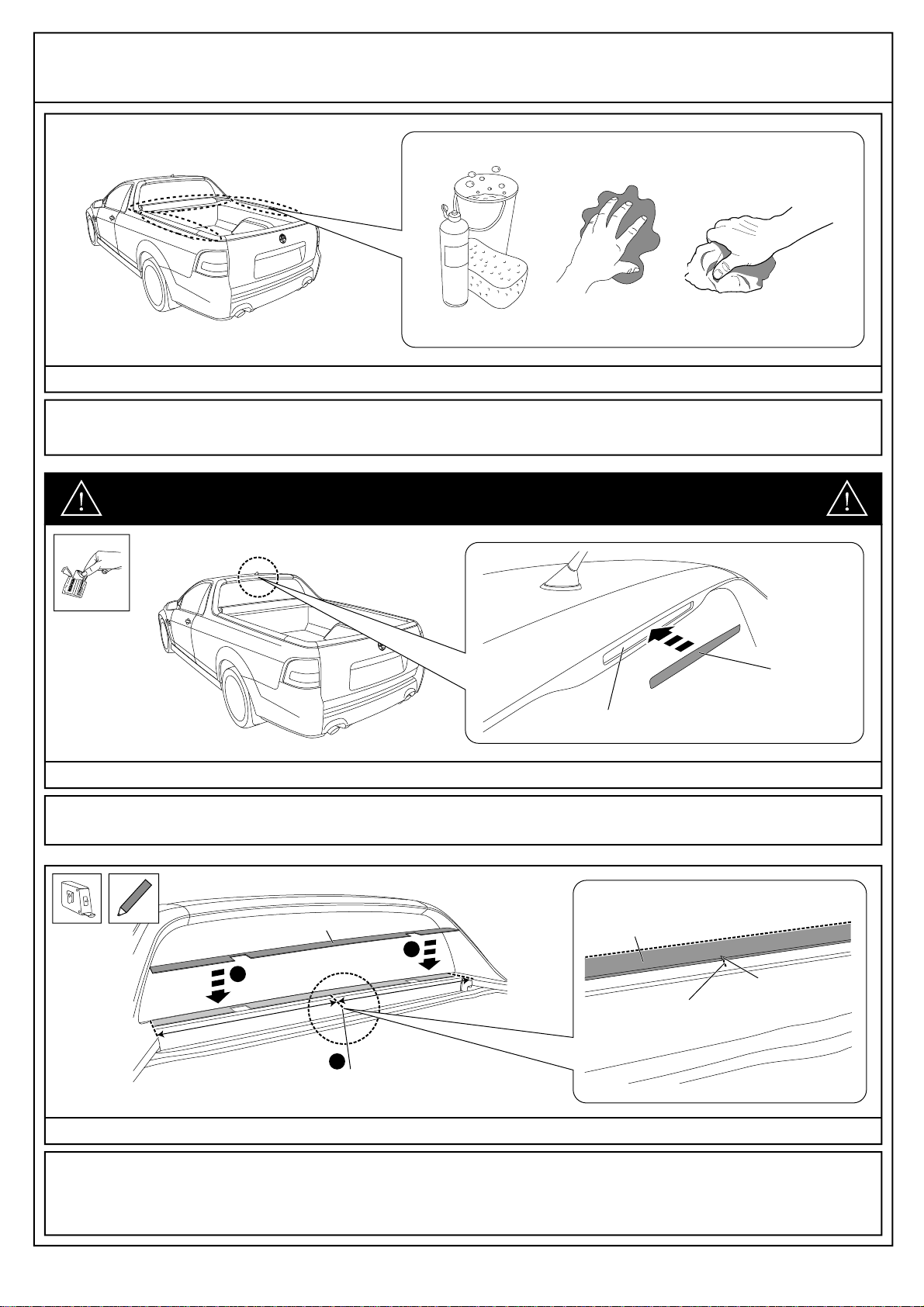
1. NOTE: Two people are required to complete installation. Thoroughly clean and dry the installation areas. See Dia #1.
Diagram #1
2. Clean the LED brake light area with the alcohol wipe provided and wipe away any residue with a dry, clean cloth.After removing the
protective lining, attach the black decal to the LED Brake light as shown, ensuring the brake light is completely covered. See Dia #2.
Diagram #2
IMPORTANT: If vehicle is fitted with an LED brake light at the top of the rear window,
proceed to Diagram #2. Otherwise, proceed to Diagram #3.
BLACK
DECAL
LED BRAKE LIGHT
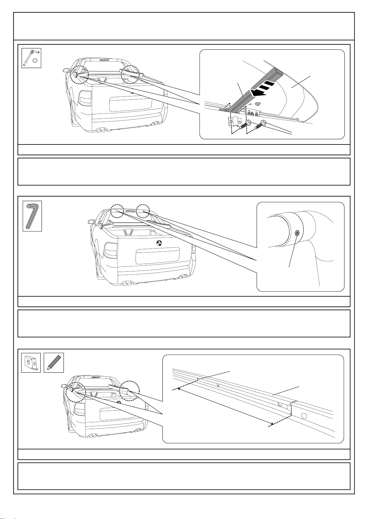
3. Using a non-permanent marker, find and mark the centre point of the header rail using a tape measure. Position the drill template
on top of header rail, aligning the edge correctly with the rear window and the notch in the centre with the marked centre point on the
header rail as shown. See Dia #3. IMPORTANT: Re-check the centre point of the header rail has been marked correctly.
Drill template MUST be centre.
Diagram #3
DRILL TEMPLATE
FIND AND MARK HEADER RAIL CENTRE POINT
1
2
2
CENTRE POINT
MARKED ON
HEADER RAIL
DRILL
TEMPLATE
NOTCH IN CENTRE
OF DRILL TEMPLATE
REAR WINDOW

TC0123b
page 6 of 28
3PC TONNEAU COVER WITH SPORTS BAR & REMOTE LOCKING
21/05/08
4. Fit hinge base plates into cut-out in drill template as shown. Mark four (4) holes in front of hinge base plate. Remove hinge base
plates. Centre punch previously marked holes and drill Ø5mm holes, followed by Ø10mm holes at the eight (8) positions. Remove any
swarf and apply rust inhibitor to all the drilled holes. Do not remove drill template at this time. See Dia #4.
Diagram #4
10mm
DRILL TEMPLATE
Ø5mm
4 5
Ø10mm
6 7
FIT
1
REMOVE
32
MARK, CENTRE PUNCH,
DRILL Ø5mm THEN Ø10mm HOLES
& APPLY RUST INHIBITOR
DRILL TEMPLATE
HINGE
BASE
PLATE
THIS STEP IS VERY IMPORTANT, PLEASE TAKE THE TIME TO ENSURE THAT IT
IS DONE CORRECTLY.
NOTE: IF YOUR WORKSHOP WILL BE INSTALLING MORE OF THESE TONNEAU COVERS IT IS
RECOMMENDED THAT YOU PURCHASE A PNEUMATIC TOOL TO ASSIST WITH THIS PROCESS.
THIS PNEUMATIC TOOL WILL BOTH ENSURE THE NUTSERTSARE INSTALLED CORRECTLYAND
SUBSTANTIALLY REDUCE INSTALLATION TIME FOR THIS STEP. DETAILS FOR THE
RECOMMENDED TOOL IS AS FOLLOWS:
PRODUCT NAME: THREADED INSERT FASTENING TOOL
MODEL NUMBER: 74200
MANUFACTURER: TEXTRON FASTENING SYSTEMS PTY LTD
ADDRESS: 891 WELLINGTON ROAD, ROWVILLE, VICTORIA, 3178.
CONTACT: PH 03 9764 3877 FAX 03 9755 7352
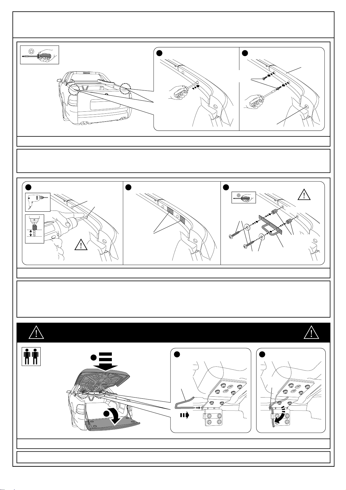
5. Attach the hex head bolt, wizlock nut and rubber washer to a nut insert as shown. Insert nut insert assembly through drilled hole in
header rail. While holding the wizlock nut in place with a 13mm spanner, tighten the bolt until the nut insert collapses completely in the
drilled hole (the nut insert is collapsed when the bolt starts to become tight, at approx torque 6Nm). Remove bolt, wizlock nut and
rubber washer. Repeat process for the remaining seven (7) drilled holes. See Dia #5.
NOTE: Replace rubber washer during each installation.
Diagram #5
NUT
INSERT
RUBBER
WASHER
WIZLOCK
NUT
NUT
INSERT
HEX
HEAD BOLT
REMOVE
HEX HEAD
BOLT
REMOVE
WIZLOCK NUT
REMOVE
RUBBER
WASHER
1 2 3 4
NUT INSERT
ASSEMBLY
HEADER RAIL
13MM
SPANNER
(HOLD NUT)
WIZLOCK NUT
ROTATE
BOLT
UNTIL TIGHT
(WITH 10MM
SOCKET)
HEADER RAIL
13mm
10mm 10mm10mm

7. Drive the countersunk self-tapping screw through the hole in the top surface both of the hinge base plates. Tighten to torque 3Nm.
See Dia #7.
Diagram #7
8.Attach the LED and the LED gasket to the Sports Bar top tube using the M4x30mm screws and M4 internal tooth washers as shown.
Tighten to torque 2Nm. Ensure the wiring connected to the LED is fed through the Sports Bar top tube and out the end as shown.
See Dia #8. NOTE: Ensure the warning label is orientated correctly. If wording is upside-down flip bar 180º, but ensure LED
wiring loom comes out the right hand end of the Sports Bar top tube.
Diagram #8
TC0123b
page 7 of 28
3PC TONNEAU COVER WITH SPORTS BAR & REMOTE LOCKING
21/05/08
COUNTERSUNK
SELF-TAPPING
SCREWS
HINGE
BASE
PLATE
TORQUE 3Nm
TOP TUBE
LED WIRING
LED
M4 INTERNAL
TOOTH
WASHERS
M4x30 SCREWS
TORQUE 2Nm
LED GASKET
6.Apply non-acetic silicon to the underside of the hinge base plates and position on the vehicle, aligning the four (4) holes on the hinge
with those on the header rail as well as inside the cut-out of the drill template. Position hinge pin locking tabs with the tabs to the left
hand of the hinge base plate across the top two fixing holes. Use the allen screws and fibre washers supplied to secure the hinges.
Tighten to torque 8Nm. See Dia #6.
Diagram #6
1
NON-ACETIC
SILICON &
CAULKING GUN
HINGE
BASE
PLATE HINGE BASE
PLATES
DRILL TEMPLATE
22
3HINGE BASE
PLATE
HINGE PIN
LOCKING TAB
ALLEN SCREWS
FIBRE WASHERS
TORQUE 8Nm

10. Loosely attach the Sports Bar top tube to the Sports Bar left hand and right hand leg using the M8x30mm black screw and M8 black
internal tooth washer as shown. Do not tighten yet. See Dia #10.
Diagram #10
9. Slide the rubber sleeves over the ends of the Sports Bar left hand leg and right hand leg and then slide the Sports Bar top tube in
as shown. Ensure that all holes are aligned with each other, and that the LED wiring is fed through the large hole in the bottom of the
Sports Bar right hand front leg. See Dia #9. NOTE: Ensure the warning label is orientated correctly. If wording is upside-down
flip bar 180º.
Diagram #9
11. Note the protective lining on back of Sports Bar foot gaskets. Trial fit the gaskets to the Sports Bar to determine which foot they are
fitted to. Remove the lining before attaching in next step. See Dia #11.
Diagram #11
TOP TUBE
RUBBER
SLEEVE
LEFT HAND
LEG
RIGHT HAND
LEG
RUBBER
SLEEVE
LEG
LEG
RUBBER
SLEEVE
RUBBER
SLEEVE
TOP
TUBE
TOP
TUBE
RIGHT
HAND
FRONT
LEG
LED
WIRING
NO POWER
TOOLS
M8 INTERNAL
TOOTH WASHER
M8x30 BLACK SCREW
FOOT GASKET
RIGHT HAND FRONT
FOOT GASKET
RIGHT HAND REAR
FOOT GASKET
LEFT HAND FRONT
FOOT GASKET
LEFT HAND REAR
TC0123b
page 8 of 28
3PC TONNEAU COVER WITH SPORTS BAR & REMOTE LOCKING
21/05/08

TC0123b
page 9 of 28
3PC TONNEAU COVER WITH SPORTS BAR & REMOTE LOCKING
21/05/08
14. Open the vehicle’s tailgate. Remove the two (2) push rivets and peel back the rubber tailgate seal as far as the base of the tailgate
as shown. See Dia #14.
Diagram #14
12. Attach the foot gaskets to their correct Sports Bar foot as shown, ensuring the holes in the Sports Bar feet remain accessible.
Repeat process for the other side of the vehicle. See Dia #12.
Diagram #12
13. Remove the three (3) tie-down brackets on the right hand of the bed using a torx-head screwdriver as shown. See Dia #13.
Diagram #13
RIGHT HAND SHOWN
FOOT GASKET
RIGHT HAND REAR
LED WIRING
SPORTS BAR
RIGHT HAND LEG
FOOT GASKET
RIGHT HAND FRONT
12
2
3
PUSH
RIVETS
TAILGATE
SEAL
TORX HEAD SCREWS
TIE-DOWN BRACKETS RIGHT HAND VIEW INSIDE VEHICLE TUB

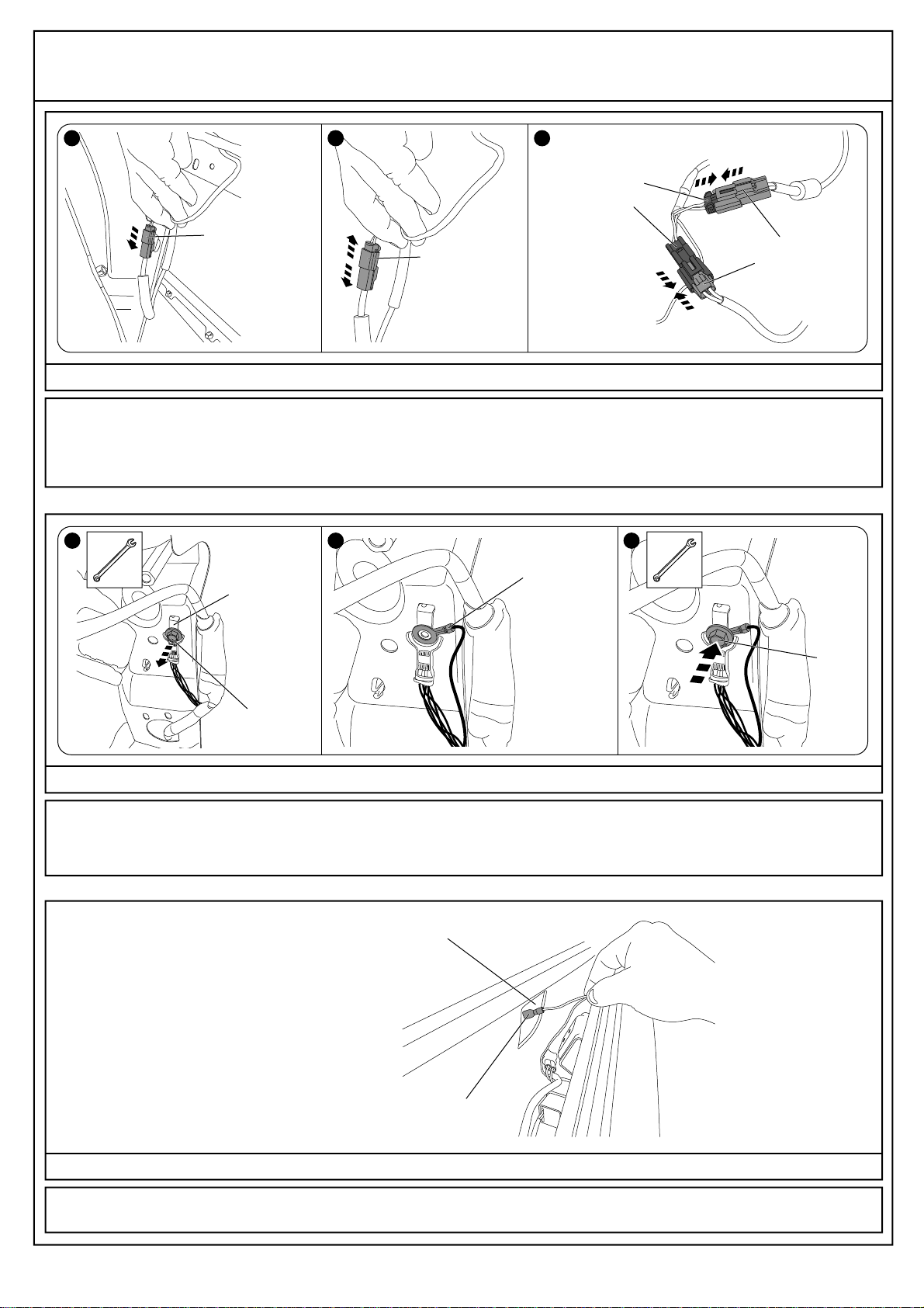
15. Lift and pull the bedliner as shown to gain access to the wiring located in the side panel of the vehicle. Disconnect the stop light
wiring plug located behind the bedliner, by pushing down on the tag on the connector using you finger or a flat blade screwdriver.
See Dia #15. NOTE: This connector is located above the wheel arch towards the rear of the vehicle.
Diagram #15
16. The hardware kit contains both the wiring adapter loom and the wiring harness. As only the wiring harness is required for this
installation, do not use the wiring adapter loom. See Dia #16.
Diagram #16
TC0123b
page 10 of 28
3PC TONNEAU COVER WITH SPORTS BAR & REMOTE LOCKING
21/05/08
17. Insert the wiring harness supplied in hardware kit between the two stop light wiring plugs as shown. See Dia #17.
Diagram #17
BEDLINER STOP LIGHT
WIRING PLUG
BEDLINER
TAILGATE
SEAL
1 2
DISCONNECT
WIRING ADAPTER
LOOM WIRING
HARNESS
DISCARD KEEP
STOP LIGHT
WIRING PLUG
STOP LIGHT
WIRING PLUG
WIRING HARNESS
SUPPLIED IN
HARDWARE KIT
CONNECT
CONNECT
18. Find the white 2-way connectors on the vehicle (directly behind the wheel arch) and unclip them from the vehicle as shown.
Disconnect the white 2-way connectors. Connect the white 2-way connectors on the wiring harness to the white 2-way connectors from
the vehicle as shown. Finally clip either of the white 2-way connectors back to where they were previously unclipped from the vehicle.
See Dia #18.
Diagram #18
2-WAY
CONNECTORS
(VEHICLE)
EARTH WIRE
TERMINAL
(VEHICLE)
EARTH WIRE
TERMINAL
(WIRING
HARNESS)
BOLT
BOLT
RE-ATTACH
BOLT
UNCLIP FROM
MOUNT DISCONNECT
TC0123b
page 11 of 28
3PC TONNEAU COVER WITH SPORTS BAR & REMOTE LOCKING
21/05/08
19. Find the earth wire terminal behind the bedliner near the vehicle’s tailgate and remove the bolt holding the terminal together as
shown. Locate the earth wire from the wiring harness and locate it over the hole that the bolt was just removed from. While holding
everything in place, re-attach the bolt to the earth wire terminal on the vehicle as shown. See Dia #19.
Diagram #19
20. Find the middle tie down bracket hole and push the spade terminal from the wiring harness through it as shown. See Dia #20.
Diagram #20
1
1
2-WAY
CONNECTORS
(VEHICLE)
2-WAY
CONNECTORS
(VEHICLE)
2-WAY
CONNECTORS
(WIRING HARNESS)
CONNECT
CONNECT
2 3
3
REMOVE
BOLT
2
MIDDLE TIE DOWN BRACKET HOLE
PUSH SPADE TERMINAL THROUGH
HOLE IN BEDLINER
SPADE TERMINAL
(WIRING HARNESS)

23. Centre punch and drill Ø5mm holes at the two (2) outer hole positions marked in the previous Diagram. Remove any drill swarf and
apply rust inhibitor. Repeat process for the other side of the vehicle. Attach the M8 hex head bolt and M8 hex nuts to the jacking
brackets as shown. Do not install the jacking bracket at this time. See Dia #23.
Diagram #23
22. Trial-fit the jacking bracket by sliding it into the side rail and aligning it with the bedliner fixture as shown. Mark the two (2) outer hole
positions on the jacking bracket. Remove the jacking bracket from the side rail. Repeat process for the other side of the vehicle.
See Dia #22.
Diagram #22
RIGHT HAND SHOWN
FRONT VIEW
JACKING
BRACKET LINER
FIXTURE
LINER
FIXTURE
x2
JACKING
BRACKET
SIDE RAIL
MARK HOLES
ALIGN
RIGHT HAND SHOWN
1
SIDE VIEW
2
Ø5mm
CENTRE PUNCH,
DRILL Ø5mm HOLES &
APPLY RUST INHIBITOR
M8 HEX
HEAD BOLT
JACKING BRACKET
M8 HEX
NUTS
TC0123b
page 12 of 28
3PC TONNEAU COVER WITH SPORTS BAR & REMOTE LOCKING
21/05/08
4-WAY GREY
CONNECTOR
WIRING HARNESS
(BEHIND BEDLINER)
21. Run the grey 4-way connector from the wiring harness all the way to the front of the tub behind the bedliner as shown. At the front
of the tub, pull the grey 4-way connector 200mm out from behind the bedliner as shown. See Dia #21.
Diagram #21
4-WAY GREY CONNECTOR
(WIRING HARNESS)
WIRING HARNESS
200mm
TC0123b
page 13 of 28
3PC TONNEAU COVER WITH SPORTS BAR & REMOTE LOCKING
21/05/08
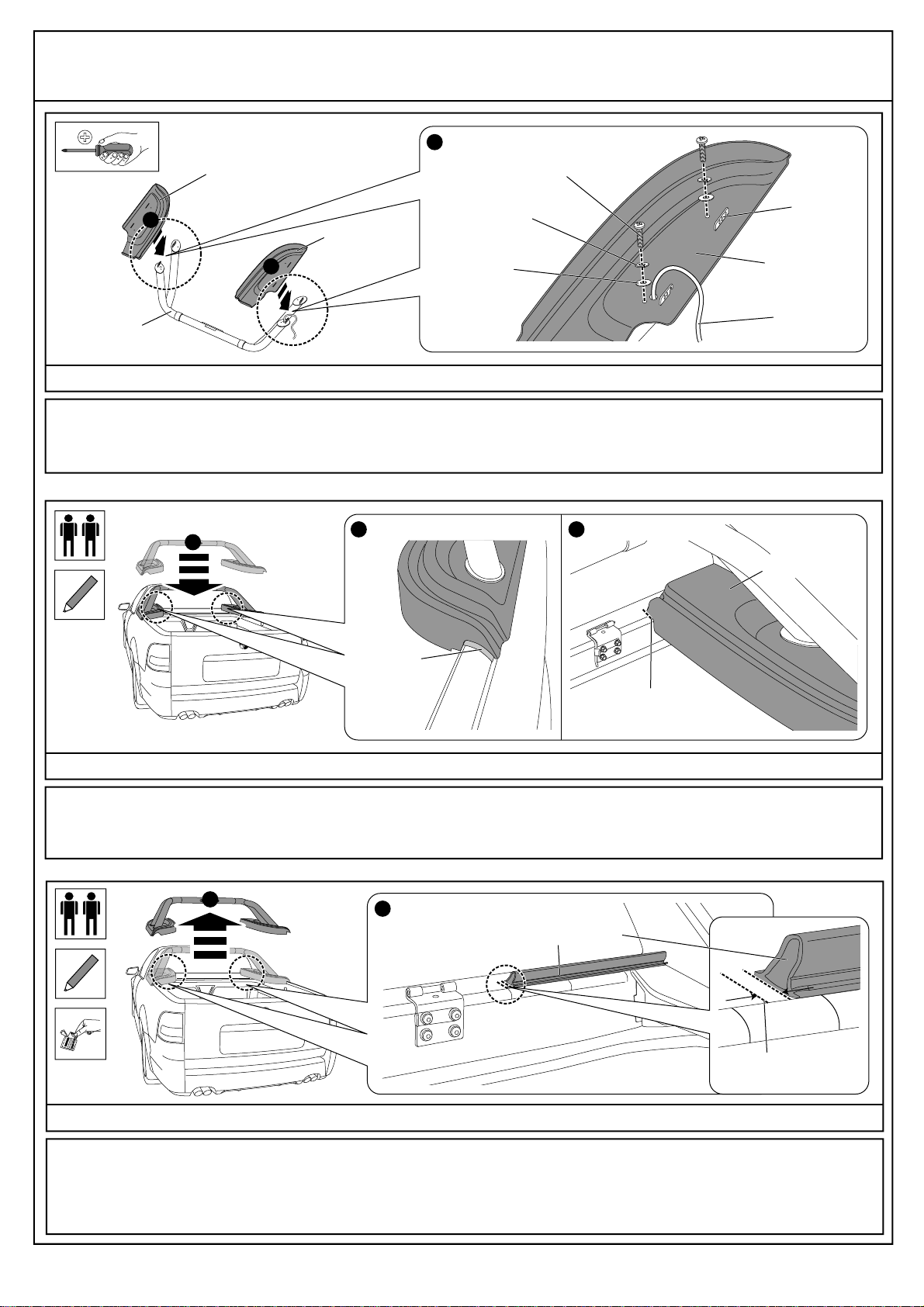
24. Fit the corner pieces to the Sports Bar feet as shown. Fasten the corner pieces in place using the M6x30mm screws, M6 spring
washers, and M6 flat washers as shown. Leave the screws loose - do not tighten yet. See Dia #24.
Diagram #24
25. Trial-fit Sports Bar onto vehicle. To protect the vehicle’s paint work, attach a clear protection pad where the corner piece meets the
side rail as shown. Draw a line along the edge of the corner piece where it meets the header rail as shown. Repeat process for the
other side of the vehicle. See Dia #25.
Diagram #25
RIGHT HAND
CORNER PIECE
LEFT HAND
CORNER PIECE
SPORTS
BAR
1
1
RIGHT HAND SHOWN
2
LED WIRING
LOOM
RIGHT HAND
CORNER PIECE
SPORTS
BAR
M6x30mm SCREWS
M6 SPRING
WASHER
M6 FLAT
WASHER
1
DRAW LINE
AGAINST EDGE
CLEAR
PROTECTION
PAD
RIGHT HAND SHOWNRIGHT HAND SHOWN
26. Remove the Sports Bar from the vehicle. Draw a parallel line 3mm to the RIGHT of the original line. Clean the header rail with
alcohol wipe provided and wipe away any residue with a clean cloth. Remove the protective liner from the rubber extrusion and attach
it to the header rail as shown. Rub down firmly to ensure good adhesion. Repeat process for the other side of the vehicle, ensuring the
parallel line is drawn 3mm to the LEFT of the original line. See Dia #26. IMPORTANT: Ensure the slant in the rubber extrusion is facing
towards the rear of the vehicle and the rubber extrusion is positioned as close to the front face of the header rail as shown.
Diagram #26
12RIGHT HAND SHOWN
RUBBER EXTRUSION
3mm
LINE DRAWN IN
PREVIOUS STEP
RIGHT HAND
CORNER PIECE
32

TC0123b
page 14 of 28
3PC TONNEAU COVER WITH SPORTS BAR & REMOTE LOCKING
21/05/08
27. Trial-fit the rubber extrusion to the header rail, aligning it with the back of the hinge base plates as shown and to the first previously
marked line. Using a non-permanent marker, draw a line along the length of the rubber extrusion. Clean the header rail with alcohol
wipe provided and wipe away any residue with a clean cloth. Remove the protective lining from the extrusion and attach it to the header
rail, aligning it with the drawn line. Rub down firmly to ensure good adhesion. See Dia #27.
IMPORTANT: Ensure the slant in the rubber extrusion is facing towards the rear of the vehicle.
Diagram #27
29. Slide the clamping plates with tapped holes into the side rail and locate centrally over the top of the previously drilled holes. Repeat
process for the other side of the vehicle. See Dia #29.
Diagram #29
28. Using a torx head screwdriver, remove and discard the torx screws from the front two (2) holes on the side rail as shown. Repeat
for the other side of the vehicle. Drill out all four (4) holes with a Ø3/16” drill. Clean away swarf from drill and drilled holes. See Dia #28.
NOTE: Be careful not to drill through the outside rail. Use 10mm drill stop as shown.
Diagram #28
10mm
SIDE RAIL
REMOVE
RIGHT HAND SHOWN RIGHT HAND SHOWN SIDE RAIL
1 2
SIDE RAIL
CLAMPING PLATES
WITH TAPPED HOLES
RIGHT HAND SHOWN
Ø3/16”
RUBBER
EXTRUSION
DRAWN LINE
TRIAL-FIT RUBBER EXTRUSION
1MARK LINE ALONG EXTRUSION
2CLEAN WITH ALCOHOL WIPES
3REMOVE PROTECTIVE LINING
4ATTACH RUBBER EXTRUSION
5
FIRST MARKED LINE
DRILL OUT HOLES
WITH 3/16” DRILL

TC0123b
page 15 of 28
3PC TONNEAU COVER WITH SPORTS BAR & REMOTE LOCKING
21/05/08
30. Fit the Sports Bar to the vehicle as shown. Note the corner piece positions over the top of the previously installed rubber extrusion.
Ensure the corner pieces are tightly fitted around the vehicle sail-plane panels, then tighten the M6 screws as shown. Tuck the LED
wiring loom up under the side rail and behind the bedliner as shown. See Dia #30.
Diagram #30
31.Attach the male wiring connector to the wiring adapter loom as shown. Feed the LED wiring loom along the inside of the side panel
and attach it to the male wiring connector. Ensure the male wiring connector is orientated correctly when attaching. See Dia #31.
* IMPORTANT: CHECK THE WIRING ADAPTER LOOM AND THE CORRECT LOCATION OF THE RED BRAKE SIGNAL WIRE TO
ENSURE THEY MATCH WHEN THE WIRES ARE INSERTED INTO THE MALE CONNECTOR. IF THE WIRES DO NOT MATCH,
THE SPORTS BAR LED WILL NOT FUNCTION.
Diagram #31
1
LED WIRING
LOOM
BEDLINER
BULB SEAL
ENSURE
TIGHT
FIT
TIGHTEN
M6 SCREWS
SPORTS BAR
RIGHT HAND LEG
CLAMPING
PLATE
2
WHITE LED
CONNECTOR
WIRING
HARNESS
LED
WIRING
LOOM
RIGHT HAND ONLY
3
WHITE LED
CONNECTOR
RED
“CLICK”
*
MALE WIRING CONNECTOR
!
“CLICK”
1
2
32. Re-attach the bedliner by lifting it back into position, re-installing the tie-down brackets (torque 10Nm), the push rivets and the
tailgate seal as shown. Ensure there is at least 150mm of the spade terminal protruding through the bedliner and that it is positioned
at the rear of the bracket and half way up the edge of the bracket. See Dia #32.
Diagram #32
TORX HEAD
SCREWS
(TORQUE 10Nm)
TIE-DOWN
BRACKETS
2
1
1
1
2
3
PUSH
RIVETS
TAILGATE
SEAL
RIGHT HAND VIEW INSIDE
VEHICLE TUB
150mm
SPADE
TERMINAL

TC0123b
page 16 of 28
3PC TONNEAU COVER WITH SPORTS BAR & REMOTE LOCKING
21/05/08
33. Attach the Sports Bar front legs to the clamping plates and side rails using the 12Gx1½” self tapping screws, M6 spring washers
and washer plates as shown. Do not tighten yet. Repeat process for the Sports Bar rear legs. See Dia #33.
Diagram #33
34. Attach the Sports Bar front legs to the clamping plates using the M6x20mm screws and M6 spring washers as shown. Do not
tighten yet. Repeat process for the Sports Bar rear legs. See Dia #34.
Diagram #34
35. Tighten all the screws on the Sports Bar right hand leg in the order A - B - C - D - E - F. TightenA, B, D & E to torque 12Nm. Tighten
C & F to torque 10Nm. Repeat process for the Sports Bar left hand leg. Visually check that all scews are home and all spring washers
are compressed. See Dia #35.
Diagram #35
CLAMPING
PLATE
M6 SPRING
WASHER
12Gx1½” SELF
TAPPING
SCREW
WASHER
PLATE
CLAMPING
PLATE
RIGHT HAND SHOWN RIGHT HAND SHOWN
RIGHT HAND
FRONT LEG RIGHT HAND
REAR LEG
M6 SPRING
WASHER
12Gx1½” SELF
TAPPING
SCREW
1 2
WASHER
PLATE
CLAMPING
PLATE
M6 SPRING
WASHER
M6x20 SCREW
M6x20 SCREW
WASHER
PLATE
CLAMPING
PLATE
RIGHT HAND SHOWN RIGHT HAND SHOWN
M6 SPRING
WASHER
WASHER
PLATE
1 2
RIGHT HAND
FRONT LEG RIGHT HAND
REAR LEG
TIGHTEN
TORQUE 12Nm
RIGHT HAND SHOWN RIGHT HAND SHOWN
1
DE
F
TIGHTEN
TORQUE 12Nm
TIGHTEN
TORQUE 10Nm
TIGHTEN
TORQUE 12Nm
C
AB
2
RIGHT HAND
FRONT LEG
RIGHT HAND
REAR LEG
TIGHTEN
TORQUE 10Nm
TIGHTEN
TORQUE 12Nm
TC0123b
page 17 of 28
3PC TONNEAU COVER WITH SPORTS BAR & REMOTE LOCKING
21/05/08
37. Tighten the M8x30mm black screws in the Sports Bar Top Tube as shown. Tighten to torque 7Nm. See Dia #37.
Diagram #37
TIGHTEN
TORQUE 7Nm
36. Attach the jacking bracket to the side rail using the hex head self-tapping screws as shown. Tighten to torque 3Nm. Repeat the
process for the other side of the vehicle. See Dia #36.
Diagram #36
38. Using a non-permanent marker, measure and mark (on the inside of the side rail), 500mm from the end of the vehicle’s rear side
rail panel as shown. Repeat process for the other side of the vehicle. See Dia #38.
Diagram #38
RIGHT HAND SHOWN
SIDE RAIL
MARK HERE
(ON INSIDE OF SIDE RAIL)
500mm
RIGHT HAND SHOWN
TORQUE
3Nm
FIT
HEX HEAD SELF-
TAPPING SCREWS
UNDERSIDE
OF CORNER
PIECE
JACKING
BRACKET

TC0123b
page 18 of 28
3PC TONNEAU COVER WITH SPORTS BAR & REMOTE LOCKING
21/05/08
40. Attach the gas strut bracket to the side rail using the hex head self-tapping screws as shown. Tighten to torque 3Nm. Attach ball
stud screw to the gas strut bracket as shown. Tighten to torque 4Nm. Repeat process for the other side of the vehicle. See Dia #40.
Diagram #40
41. Drill Ø5mm holes through the plastic plugs located in the rear of the side rail as shown. Remove the plugs using a screwdriver.
Repeat process for the other side of the vehicle. See Dia #41.
Diagram #41
GAS STRUT
BRACKET
SELF-TAPPING
SCREW
TORQUE 3Nm
SELF-TAPPING
SCREW
TORQUE 3Nm
BALL STUD
SCREW
TORQUE 4Nm
RIGHT HAND SHOWN
1
12
10mm
Ø5mm RIGHT HAND SHOWN RIGHT HAND SHOWN
REMOVE
DRILL
PLASTIC
PLUGS
1 2
39. Fit the gas strut bracket into the side rail, aligning it with the previously drawn mark as shown. Centre punch and drill Ø5mm holes
at the two (2) outer hole positions on the gas strut bracket. Clean away drill swarf and apply rust inhibitor to the drilled holes and repeat
process for the other side of the vehicle. See Dia #39.
Diagram #39
10mm
Ø5mm
1 2 3
GAS STRUT
BRACKET
ALIGN BRACKET
WITH MARK
CENTRE PUNCH,
DRILL Ø5mm HOLES &
APPLY RUST INHIBITOR
RIGHT HAND
SHOWN
TC0123b
page 19 of 28
3PC TONNEAU COVER WITH SPORTS BAR & REMOTE LOCKING
21/05/08
44. Open vehicle’s tailgate. Fit Tonneau Cover and secure hinges with hinge pins as shown. See Dia #44.
Diagram #44
IMPORTANT: Ensure vehicles’s tailgate is opened before installing Tonneau Cover,
as locking mechanism may not function until adjusted correctly.
“CLICK”
RIGHT HAND SHOWN
4
HINGE
PIN
HINGE
PIN
RIGHT HAND SHOWN
3
2
1
43. Drill the threads in the side rail panel using a Ø3/16” drill with a 10mm drill stop as shown. Clean away drill swarf. To prevent paint
scratching, attach two (2) clear protection pads to the side rail panel as shown.Attach the lock striker bracket to the side rail panel using
the 12g self-tapping screws, flat washers (14mm x 5.5mm) and plastic spacers as shown. DO NOT OVERTIGHTEN! Repeat process
for the other side of the vehicle. See Dia #43. NOTE: Plastic spacers fit inside the side rail panel between the thread nut and lock
striker bracket.
Diagram #43
RIGHT HAND SHOWN RIGHT HAND SHOWN
ATTACH
RIGHT HAND SHOWN
DRILL THREAD
WITH Ø3/16”
DRILL 12gx1½”
SELF-TAPPING
SCREWS
CLEAR
PROTECION
PADS
FLAT WASHERS
(14mm x 5.5mm)
1 32
USE 10mm
DRILL STOP
LOCK STRIKER
BRACKET
PLASTIC
SPACERS
DO NOT
OVER-TIGHTEN
10mm
Ø3/16”
42. Using a torx head screwdriver, retrieve the torx head screws from inside the side rail panel as shown. If you drop one of the torx
head screws inside the panel, simply remove the 3rd screw and slide the panel upwards to retrieve it. Repeat process for the other side
of the vehicle. See Dia #42.
Diagram #42
RIGHT HAND SHOWN RIGHT HAND SHOWN
1 2
TORX HEAD
SCREWS
3RD SCREW
SIDE RAIL
PANEL
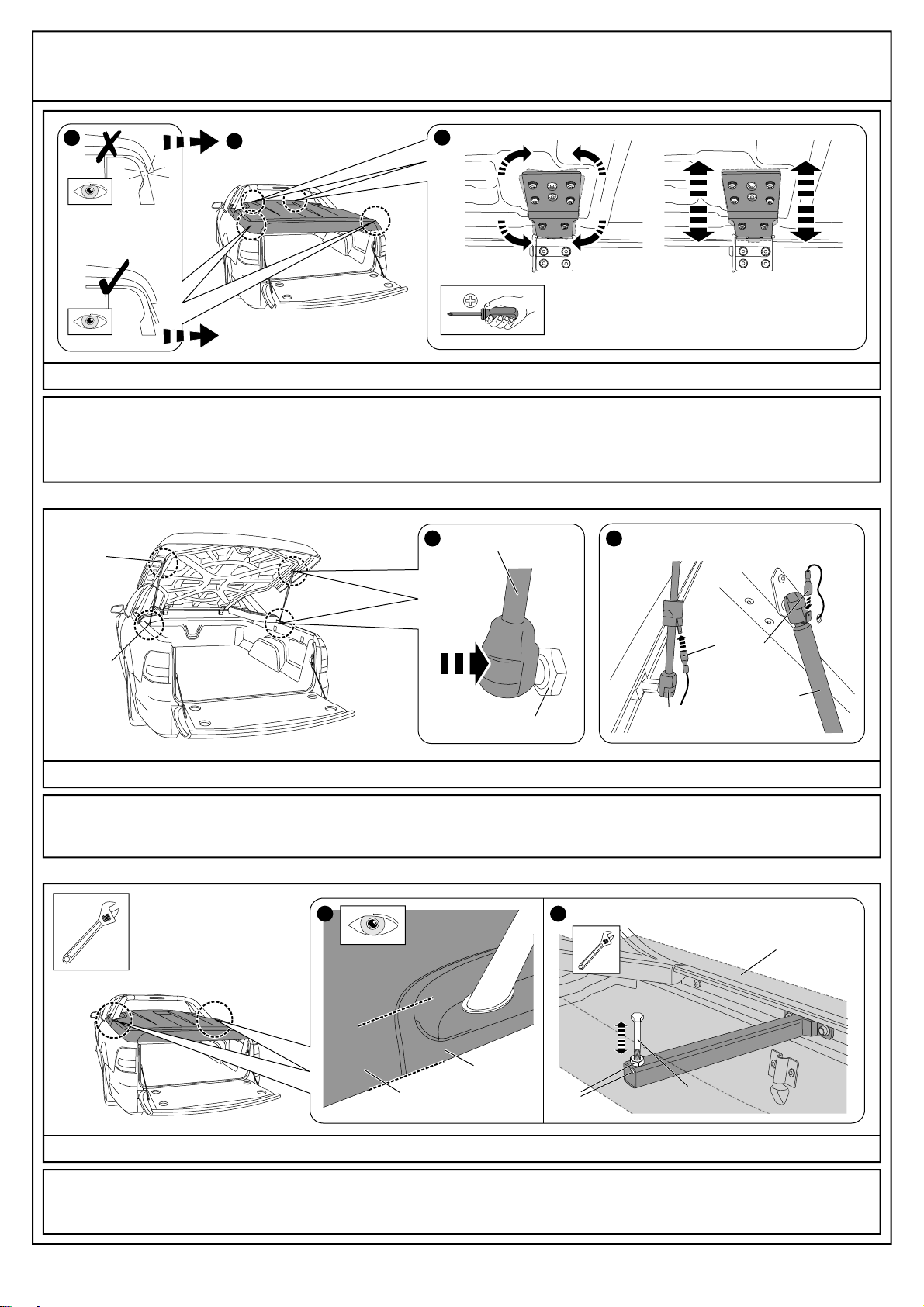
45. Check Tonneau Cover is central to vehicle and the sides of Tonneau Cover do not contact the vehicle bed rail. Adjust position if
necessary by loosening the top hinge screws and re-positioning Tonneau Cover to fit centrally on vehicle. Re-tighten hinges to torque
5Nm. See Dia #45.
Diagram #45
46. Attach the gas struts by clipping them into place as shown. ENSURE THE NARROW END MOUNTS TO THE VEHICLE. Connect
the wiring harness to the terminals on the driver’s side gas strut as shown. See Dia #46. NOTE: Attach gas strut with terminals to
the driver’s side of the vehicle.
Diagram #46
TC0123b
page 20 of 28
3PC TONNEAU COVER WITH SPORTS BAR & REMOTE LOCKING
21/05/08
NEXT STEP
RE-TORQUE 5Nm
ENSURE
CLEARANCE
TO TUB
LOOSEN HINGE SCREWS
TO ADJUST TONNEAU
POSITION IF NECESSARY
122
GAS STRUT DRIVER’S SIDE ONLY
47. Adjust jacking bolts until corner pieces are level with the main surface of the Tonneau Cover. Once in the correct position, lock the
M8 nuts into position against the bracket using a spanner. Repeat for other side of vehicle. See Dia #47.
Diagram #47
RIGHT HAND SHOWN
CORNER
PIECE
TONNEAU
COVER
1 2
M8
NUTS
M8 HEX
HEAD BOLT
CORNER
PIECE
LARGE
END
NARROW
END
1 2
GAS STRUT
BOTTOM
GAS
STRUT
TOP
WIRING
HARNESS
Table of contents
Other EGR Automobile Accessories manuals


